JP2006123731A - Seat mounting structure - Google Patents
Seat mounting structure Download PDFInfo
- Publication number
- JP2006123731A JP2006123731A JP2004314925A JP2004314925A JP2006123731A JP 2006123731 A JP2006123731 A JP 2006123731A JP 2004314925 A JP2004314925 A JP 2004314925A JP 2004314925 A JP2004314925 A JP 2004314925A JP 2006123731 A JP2006123731 A JP 2006123731A
- Authority
- JP
- Japan
- Prior art keywords
- seat
- floor tunnel
- mounting structure
- side sill
- slide rail
- Prior art date
- Legal status (The legal status is an assumption and is not a legal conclusion. Google has not performed a legal analysis and makes no representation as to the accuracy of the status listed.)
- Pending
Links
Images



Landscapes
- Body Structure For Vehicles (AREA)
Abstract
【課題】 簡単な構成で側突時の車体変形を抑制できるシート取り付け構造を提供する。
【解決手段】 本発明のシート取り付け構造は、サイドシル3とフロアトンネル2との間にシート6を取り付けたものにおいて、サイドシル3とフロアトンネル2との間に、側突時にサイドシル3に加わる外力をフロアトンネル2に伝達する橋渡し部材10が掛け渡して設けられている。
【選択図】 図1
PROBLEM TO BE SOLVED: To provide a seat mounting structure capable of suppressing deformation of a vehicle body at a side collision with a simple configuration.
SOLUTION: In the seat mounting structure of the present invention, when a seat 6 is mounted between a side sill 3 and a floor tunnel 2, an external force applied to the side sill 3 during a side collision is applied between the side sill 3 and the floor tunnel 2. A bridging member 10 that is transmitted to the floor tunnel 2 is provided over the floor tunnel 2.
[Selection] Figure 1
Description
本発明は、サイドシルとフロアトンネルとの間にシートを取り付けたシート取り付け構造の改良に関する。 The present invention relates to an improvement in a seat mounting structure in which a seat is mounted between a side sill and a floor tunnel.
従来から、シート取り付け構造には、サイドシルとフロアトンネルとの間にシートを車両前後方向にスライド可能に取り付けたものが知られている(例えば、特許文献1参照。)。 2. Description of the Related Art Conventionally, a seat mounting structure is known in which a seat is slidably mounted in a vehicle front-rear direction between a side sill and a floor tunnel (see, for example, Patent Document 1).
このものでは、側突時に車幅方向外側から車体に加わる外力を内側へ伝達する連結部材がシートクッションに設けられている。
しかしながら、この従来のシート取り付け構造では、側突時の車体変形を抑制するには不十分であり、更なる改善が望まれている。この側突時の車体変形をあえて抑制する構造にするには、車体に質量の大きな補強部材を設けなければならず、重量が増加するという問題がある。 However, this conventional seat mounting structure is insufficient for suppressing vehicle body deformation at the time of a side collision, and further improvement is desired. In order to deliberately suppress the deformation of the vehicle body at the time of the side collision, a reinforcing member having a large mass must be provided on the vehicle body, which causes a problem that the weight increases.
本発明は、上記の事情に鑑みて為されたもので、簡単な構成で側突時の車体変形を抑制できるシート取り付け構造を提供することを目的とする。 The present invention has been made in view of the above circumstances, and an object thereof is to provide a seat mounting structure that can suppress deformation of a vehicle body at the time of a side collision with a simple configuration.
請求項1に記載のシート取り付け構造は、サイドシルとフロアトンネルとの間にシートを取り付けたシート取り付け構造において、前記サイドシルと前記フロアトンネルとの間に、側突時にサイドシルに加わる外力を前記フロアトンネルに伝達する橋渡し部材が掛け渡して設けられていることを特徴とする。
The seat mounting structure according to
請求項2に記載のシート取り付け構造は、前記シートが車両前後方向にスライド可能に設けられ、前記サイドシルの側壁と前記フロアトンネルの側壁とには車両前後方向に延びるスライドレールが設けられ、前記シートには前記スライドレールに案内される一対の被案内レールが車幅方向に間隔を開けて設けられ、前記橋渡し部材が前記スライドレールに設けられていることを特徴とする。
The seat mounting structure according to
請求項3に記載のシート取り付け構造は、前記橋渡し部材が前記シートに設けられた被案内レールの下方に設けられていることを特徴とする。 The seat mounting structure according to claim 3 is characterized in that the bridging member is provided below a guided rail provided on the seat.
請求項4に記載のシート取り付け構造は、前記スライドレールと前記フロアトンネルとの間に、前記フロアトンネルから前記サイドシルまでの間隔と前記シートに設けられた被案内レールの車幅方向間隔との寸法差を調節するためのアジャスト機構が設けられていることを特徴とする。 The seat mounting structure according to claim 4, wherein a dimension between a distance from the floor tunnel to the side sill and a distance in a vehicle width direction of the guided rail provided on the seat is between the slide rail and the floor tunnel. An adjustment mechanism for adjusting the difference is provided.
請求項1に記載の発明によれば、フロアトンネルとサイドシルとの間にこれを横断する橋渡し部材を設けたので、側突時に外部から車体に加わる入力モーメントを減少させることができることになり、簡単な構成で側突時の車体変形を抑制できる。 According to the first aspect of the present invention, since the bridging member is provided between the floor tunnel and the side sill, the input moment applied to the vehicle body from the outside at the time of a side collision can be reduced. The vehicle body deformation at the time of a side collision can be suppressed with a simple configuration.
シートの車幅方向の取り付けスパンを拡げることができるので、シート保持の際の剛性の向上を期待できる。また、後席に座っている着座者が脚のつま先を前席のシートクッションの下方空間に入れやすくなり、後席の着座者の快適性が向上する。 Since the mounting span of the seat in the vehicle width direction can be expanded, it is possible to expect an improvement in rigidity when holding the seat. In addition, the seated person sitting in the rear seat can easily put the toe of the leg into the lower space of the seat cushion in the front seat, and the comfort of the seated person in the rear seat is improved.
請求項2に記載の発明によれば、橋渡し部材を車体側のスライドレールに設けたので、側突時に外部から車体に加わる外力を車体内部に効率よく伝達できる。 According to the second aspect of the present invention, since the bridging member is provided on the slide rail on the vehicle body side, an external force applied to the vehicle body from the outside during a side collision can be efficiently transmitted to the inside of the vehicle body.
請求項3に記載の発明によれば、橋渡し部材をシートに設けられた被案内レールの下方に設けたので、シートスライド機能を阻害することなく、かつ、小型軽量化を実現しつつ側突時に外部から車体に加わる外力を車体内部に効率よく伝達できる。 According to the invention described in claim 3, since the bridging member is provided below the guided rail provided on the seat, the side slide function can be achieved without impeding the seat slide function and realizing a small size and light weight. An external force applied to the vehicle body from outside can be efficiently transmitted to the inside of the vehicle body.
請求項4に記載の発明によれば、前記スライドレールと前記フロアトンネルとの間に、前記フロアトンネルから前記サイドシルまでの間隔と前記シートに設けられた一対の被案内レールの車幅方向間隔との寸法差を調節するためのアジャスト機構を設けたので、シートのスライド性能を損なうことなく側突時に外部から車体に加わる外力を車体内部に効率よく伝達できる。 According to the invention described in claim 4, between the slide rail and the floor tunnel, an interval from the floor tunnel to the side sill and an interval in the vehicle width direction of the pair of guided rails provided on the seat. Since an adjustment mechanism for adjusting the dimensional difference is provided, an external force applied from the outside to the vehicle body at the time of a side collision can be efficiently transmitted to the inside of the vehicle body without impairing the sliding performance of the seat.
以下、本発明に係わるシート取り付け構造の発明の実施の形態を図面に示す実施例を参照しつつ説明する。 DESCRIPTION OF THE PREFERRED EMBODIMENTS Embodiments of a seat mounting structure according to the present invention will be described below with reference to the embodiments shown in the drawings.
(実施例1)
図1において、1はフロア、2はフロアトンネル、3はサイドシルである。フロアトンネル2とサイドシル3との間には、シートクッション4とシートバック5とから大略構成されたシート6が車両前後方向にスライド可能に設けられる。そのサイドシル3はインナーシル3Aとアウターシル3Bとから構成されている。そのインナーシル3Aにはフロア1の起立壁1Aに接合され、その起立壁1Aはサイドシル3の側壁部となっている。
Example 1
In FIG. 1, 1 is a floor, 2 is a floor tunnel, and 3 is a side sill. Between the
そのシートクッション4の内部には長方形状のフレーム5が設けられ、このフレーム5には車幅方向に間隔を開けて一対の脚部6A、6Aが設けられている。この一対の脚部6A、6Aにはそれぞれ被案内レール7、7が設けられている。
A
フロアトンネル2の側壁部2Aとサイドシル3の側壁部とには、車両前後方向に延びるスライドレール板8、8が設けられている。このスライドレール板8、8には被案内レール7、7を案内するガイドレール部9、9が設けられている。被案内レール7、7はそのガイドレール部9、9に案内される。
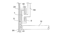
そのガイドレール部9、9と被案内レール7、7との間には、図2に拡大して示すように適宜の間隙H1、H2が設定されて、シート6のスライドが滑らかに行われるようになっている。
Appropriate gaps H1 and H2 are set between the
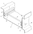
一対のスライドレール板8、8にはシートクッション4の下方に位置してフロアトンネル2とサイドシル3とを横断する方向に延びる橋渡し部材10が設けられている。この橋渡し部材10はここでは円柱パイプ部材から構成されている。
The pair of
スライドレール板8、8には、図3に示すようにそのガイドレール部9、9よりも下方に取り付け部9A、9Aが形成され、その橋渡し部材10の両端部はその取り付け部9A、9Aに溶接固着されている。その橋渡し部材10、10は図4に示すように車両前後方向に間隔を開けて一対設けられ、側突時にサイドシル3に加わる外力F(図1参照)をフロアトンネル2に伝達する役割を果たす。
As shown in FIG. 3, the
その橋渡し部材10、10をシートクッション4の下方に設けると、シート6のスライドの邪魔にならないので、図4(a)に示すように、シート6の車両前後方向の全長に対してスライドレール板8、8の車両前後方向の全長を短くできることになり、側突時の車両の変形対策を講じつつも軽量かつ小型化を実現できる。
When the
これに対して、図4(b)に示すように、シート6の車両前後方向の全長に対してスライドレール板8、8の全長を長くして、橋渡し部材10、10をシートクッション4の上方に設ける構成とした場合には、軽量かつ小型化の実現を犠牲にすることにはなるが、この場合でも、シート6のスライドを邪魔することなく側突時の車両の変形対策を講じることができる。
On the other hand, as shown in FIG. 4B, the length of the
なお、この図4において、符号Zfはシート6のスライド方向最先端位置を示し、符号Zbはシート6のスライド方向最後端位置を示す。
(実施例2)
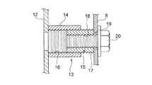
フロアトンネル2の側壁部2Aには、側壁部2Aの傾斜を考慮してスライドレール板8、8を垂直に立設するため、取り付け座12が車両前後方向に間隔を開けて一対設けられている。この取り付け座12にはアジャスト機構13が設けられている。このアジャスト機構13は外側アジャストナット14と内側アジャストナット15から構成されている。外側アジャストナット14はその内周にネジ部16が形成され、内側アジャストナット15にはその外周と内周とにネジ部17、18が形成されている。外側アジャストナット14の一端部は取り付け座12に溶接固定されている。
In FIG. 4, reference sign Zf indicates the most forward position in the sliding direction of the sheet 6, and reference sign Zb indicates the rearmost position in the sliding direction of the sheet 6.
(Example 2)
A pair of
内側アジャストナット15は外側アジャストナット14に螺合され、外側アジャストナット14のネジ部16と内側アジャストナット15のネジ部17とは逆ネジの関係になっている。スライドレール板8、8には取り付けボルト挿通穴19が形成され、取り付けボルト20を内側アジャストナット15に螺合させて、この取り付けボルト20を締め込むと内側アジャストナット15が外側アジャストナット14から突出して、フロアトンネル2に取り付けられたスライドレール板8からサイドシル3の側壁部に取り付けられたスライドレール板8までの間隔が調節され、これにより、フロアトンネル2からサイドシル3までの間隔S1(図1参照)とシート6に設けられた一対の被案内レール7、7の車幅方向幅S2との寸法差を調節することができる。その結果、シート6のスライド性能を損なうことなく側突時に外部から車体に加わる外力Fを車体内部に効率よく伝達できることになる。
The
以上、発明の実施形態について説明したが、シート6の脚部6Aに設けられた一対の被案内レール6A、6Aをフロアトンネル2の側壁部2Aとサイドシル3の側壁部とにボルト(図示を略す)を介して直接締結し、シート6をフロアトンネル2とサイドシル3との間に固定する構成のシート取り付け構造にあっては、一対の被案内レール7、7に橋渡し部材10を設けて、側突時に外部から車体に加わる外力を減少させるようにしても良い。
As described above, the embodiment of the invention has been described. A pair of guided
2…フロアトンネル
3…サイドシル
6…シート
10…橋渡し部材
2 ... floor tunnel 3 ... side sill 6 ...
Claims (4)
Priority Applications (1)
| Application Number | Priority Date | Filing Date | Title |
|---|---|---|---|
| JP2004314925A JP2006123731A (en) | 2004-10-29 | 2004-10-29 | Seat mounting structure |
Applications Claiming Priority (1)
| Application Number | Priority Date | Filing Date | Title |
|---|---|---|---|
| JP2004314925A JP2006123731A (en) | 2004-10-29 | 2004-10-29 | Seat mounting structure |
Publications (1)
| Publication Number | Publication Date |
|---|---|
| JP2006123731A true JP2006123731A (en) | 2006-05-18 |
Family
ID=36718871
Family Applications (1)
| Application Number | Title | Priority Date | Filing Date |
|---|---|---|---|
| JP2004314925A Pending JP2006123731A (en) | 2004-10-29 | 2004-10-29 | Seat mounting structure |
Country Status (1)
| Country | Link |
|---|---|
| JP (1) | JP2006123731A (en) |
Cited By (2)
| Publication number | Priority date | Publication date | Assignee | Title |
|---|---|---|---|---|
| US8894130B2 (en) | 2011-02-15 | 2014-11-25 | Toyota Jidosha Kabushiki Kaisha | Vehicle lower section structure |
| JP2025007475A (en) * | 2023-06-30 | 2025-01-17 | トヨタ自動車株式会社 | Vehicle underside structure for electric vehicle and vehicle seat structure |
Citations (5)
| Publication number | Priority date | Publication date | Assignee | Title |
|---|---|---|---|---|
| JPS5719134U (en) * | 1980-07-07 | 1982-02-01 | ||
| JPS59163533U (en) * | 1983-04-19 | 1984-11-01 | 日産自動車株式会社 | Seat cross member mounting structure |
| JPH06255414A (en) * | 1993-03-03 | 1994-09-13 | Ikeda Bussan Co Ltd | Seat for automobile |
| JP2002079864A (en) * | 2000-09-08 | 2002-03-19 | Kanto Auto Works Ltd | Car |
| JP2003146248A (en) * | 2001-11-13 | 2003-05-21 | Fuji Heavy Ind Ltd | Body structure |
-
2004
- 2004-10-29 JP JP2004314925A patent/JP2006123731A/en active Pending
Patent Citations (5)
| Publication number | Priority date | Publication date | Assignee | Title |
|---|---|---|---|---|
| JPS5719134U (en) * | 1980-07-07 | 1982-02-01 | ||
| JPS59163533U (en) * | 1983-04-19 | 1984-11-01 | 日産自動車株式会社 | Seat cross member mounting structure |
| JPH06255414A (en) * | 1993-03-03 | 1994-09-13 | Ikeda Bussan Co Ltd | Seat for automobile |
| JP2002079864A (en) * | 2000-09-08 | 2002-03-19 | Kanto Auto Works Ltd | Car |
| JP2003146248A (en) * | 2001-11-13 | 2003-05-21 | Fuji Heavy Ind Ltd | Body structure |
Cited By (3)
| Publication number | Priority date | Publication date | Assignee | Title |
|---|---|---|---|---|
| US8894130B2 (en) | 2011-02-15 | 2014-11-25 | Toyota Jidosha Kabushiki Kaisha | Vehicle lower section structure |
| JP2025007475A (en) * | 2023-06-30 | 2025-01-17 | トヨタ自動車株式会社 | Vehicle underside structure for electric vehicle and vehicle seat structure |
| JP7878184B2 (en) | 2023-06-30 | 2026-06-23 | トヨタ自動車株式会社 | Underbody structure and seat structure for electric vehicles |
Similar Documents
| Publication | Publication Date | Title |
|---|---|---|
| JP5463659B2 (en) | Seat cushion structure for vehicle seat | |
| JP5338813B2 (en) | Folding seat | |
| JP2002283891A (en) | Seat back frame for vehicle seat | |
| US20170334318A1 (en) | Seat cushion adjuster, seat, and adjustment method of seat | |
| JP2006231978A (en) | Body front structure | |
| JP6169134B2 (en) | Vehicle seat rail | |
| JP6519389B2 (en) | Vehicle seat frame | |
| JP5906707B2 (en) | Seat frame structure for vehicle seat | |
| US10399465B2 (en) | Seat cushion adjuster, seat, and adjustment method of seat | |
| JP2001260726A (en) | Vehicle seat | |
| JP4087764B2 (en) | Seat back frame for automobile seat | |
| CN107826002B (en) | Vehicle seat with energy management frame | |
| JP2003146248A (en) | Body structure | |
| JP3740933B2 (en) | Vehicle seat | |
| JP3378217B2 (en) | Rail structure of seat slide device | |
| JP2019001260A (en) | Vehicle seat rail | |
| JP6390288B2 (en) | Seat back frame structure | |
| JP2008285103A (en) | Vehicle seat frame structure | |
| JP2001058527A (en) | Vehicle seat device | |
| JP4396566B2 (en) | Structure of vehicle seat support | |
| JP5548022B2 (en) | Side collision prevention structure for vehicle seats | |
| JP7263937B2 (en) | vehicle seat | |
| JP2001341565A (en) | Car seats | |
| JP2007131135A (en) | Body front structure | |
| JP2008265456A (en) | Support structure for vehicle seat |
Legal Events
| Date | Code | Title | Description |
|---|---|---|---|
| A621 | Written request for application examination |
Free format text: JAPANESE INTERMEDIATE CODE: A621 Effective date: 20070925 |
|
| A977 | Report on retrieval |
Effective date: 20100128 Free format text: JAPANESE INTERMEDIATE CODE: A971007 |
|
| A131 | Notification of reasons for refusal |
Free format text: JAPANESE INTERMEDIATE CODE: A131 Effective date: 20100202 |
|
| A521 | Written amendment |
Effective date: 20100226 Free format text: JAPANESE INTERMEDIATE CODE: A523 |
|
| A02 | Decision of refusal |
Effective date: 20100615 Free format text: JAPANESE INTERMEDIATE CODE: A02 |