JP2006123739A - Mounting parts fixing structure - Google Patents
Mounting parts fixing structure Download PDFInfo
- Publication number
- JP2006123739A JP2006123739A JP2004315114A JP2004315114A JP2006123739A JP 2006123739 A JP2006123739 A JP 2006123739A JP 2004315114 A JP2004315114 A JP 2004315114A JP 2004315114 A JP2004315114 A JP 2004315114A JP 2006123739 A JP2006123739 A JP 2006123739A
- Authority
- JP
- Japan
- Prior art keywords
- locking
- fixing structure
- locking claws
- mounting
- mounting part
- Prior art date
- Legal status (The legal status is an assumption and is not a legal conclusion. Google has not performed a legal analysis and makes no representation as to the accuracy of the status listed.)
- Withdrawn
Links
- 210000000078 claw Anatomy 0.000 claims abstract description 97
- 238000003780 insertion Methods 0.000 description 10
- 230000037431 insertion Effects 0.000 description 10
- 238000009434 installation Methods 0.000 description 2
- 238000000034 method Methods 0.000 description 2
- 230000002452 interceptive effect Effects 0.000 description 1
- 238000012423 maintenance Methods 0.000 description 1
- 230000000452 restraining effect Effects 0.000 description 1
- 230000001360 synchronised effect Effects 0.000 description 1
Images
Landscapes
- Vehicle Interior And Exterior Ornaments, Soundproofing, And Insulation (AREA)
- Insertion Pins And Rivets (AREA)
Abstract
【課題】 比較的柔軟な係止爪を使用しても、係止・固定後に妄りに抜け落ちることがなく、相反する容易な挿入と確実な固定を共に可能にするトリム部材等の取付部品固定構造を提供することを目的とする。
【解決手段】 抜止部5B、6Bを有する間隔変更自在な一対の係止爪5、6をトリム部材1に設けるとともに、これら一対の係止爪5、6間に進入可能な間隔保持部材7を係止爪5、6あるいはトリム部材1に揺動自在に設けたので、比較的柔軟な可撓性のある間隔変更自在な一対の係止爪5、6を、容易に車体パネル2の取付孔3に挿入して作業効率が高められ、取付孔3の前縁部3F等に突き当たって一対の係止爪5、6間に強制的に進入する間隔保持部材7の作用により、係止爪5、6の抜止部5B、6Bが取付孔3から抜け落ちることがない。
【選択図】 図1PROBLEM TO BE SOLVED: To provide a fixing structure for a mounting member such as a trim member which can be easily inserted and securely fixed without conflicting even after a relatively flexible locking claw is used, without being lost after locking and fixing. The purpose is to provide.
A pair of locking claws (5, 6) having retaining portions (5B, 6B) capable of changing a distance is provided on a trim member (1), and a gap holding member (7) capable of entering between the pair of locking claws (5, 6) is provided. Since the locking claws 5 and 6 or the trim member 1 are swingably provided, the pair of locking claws 5 and 6 that are relatively soft and flexible and can be easily changed in distance can be easily attached to the mounting holes of the vehicle body panel 2. 3 and the working efficiency is increased, and the locking claw 5 is brought into contact with the front edge portion 3F of the mounting hole 3 by the action of the interval holding member 7 that forcibly enters between the pair of locking claws 5 and 6. , 6 does not fall out of the mounting hole 3.
[Selection] Figure 1
Description
本発明は、取付部品に設けた係止爪を車体パネル等の取付孔に固定するように構成した取付部品固定構造に関する。トリム部材の固定の他に、適宜の取付部品の車体パネル等への固定にも適用できる。 The present invention relates to a mounting part fixing structure configured to fix a locking claw provided on a mounting part to a mounting hole of a vehicle body panel or the like. In addition to fixing the trim member, it can also be applied to fixing an appropriate mounting part to a vehicle body panel or the like.
従来、自動車等の車体内装材であるトリム部材を車体パネルに取り付けるために様々な方式が提案されている。通常、取付部品であるトリム部材等を車体パネルに取り付けるためには、取付部品側の抜止部を有し可撓性のある係止爪を車体パネルの取付孔に挿入して固定していた。係止爪が比較的剛性のあるものであれば、確実に固定されて抜止部が係止後に抜け落ちることはないが、挿入時の抵抗が大きく作業効率が低下した。そこで、係止構造において、被取付部材への取付部材への挿入抵抗をなくし、作業性を向上させたものが提案された(例えば下記特許文献1参照)。
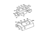
図7を用いて前記特許文献1に開示された係止構造について説明する。ロッキングノブカプラー110の枠部112の短辺112C、112Dの下面には、同一対角線上に配置された爪116、122と爪118、120とが形成される。爪116、122の係合部116A、122Aの高さは、爪118、120の係合部118A、120Aの高さより低く設定されており、係合部116Aの高さと係合部122Aの高さとが同一とされ、係合部118Aの高さと係合部120Aの高さとが同一とされている。ドアトリム130には係止孔132が穿設されており、長手方向両端部側面132A、132Bの幅方向の半分の部位には、ロッキングノブカラー110をドアトリム130に取り付ける際に、ロッキングノブカラー110の爪118、120が、ドアトリム130と干渉しないようにするための凹部134、136が形成されたものである。
The locking structure disclosed in
このような構成により、高さを少なくとも2種類設定した複数の爪を有する取付部材が、爪の係止によって厚さの異なる被取付部材の係止部に取付可能とされた係止構造において、係止部の側面に、爪のうち係止に使用されない爪の挿入時の移動軌跡と干渉しない凹部を形成したので、被取付部材への取付部材の挿入抵抗を小さくでき、作業性を向上させることが可能となった。しかしながら、このような従来のものにあって、確かに取付部材の被取付部材への挿入抵抗を小さくできたものの、挿入の容易さは依然として爪の柔軟性に依存していた。したがって、挿入の容易さは必然的に抜け易さを引き起こした。 With such a configuration, in the locking structure in which the mounting member having a plurality of claws having at least two types of heights can be attached to the locking portions of the mounted members having different thicknesses by the locking of the claws, Since a recess that does not interfere with the movement trajectory when inserting a nail that is not used for locking is formed on the side surface of the locking portion, the insertion resistance of the mounting member to the mounted member can be reduced, and workability is improved. It became possible. However, in such a conventional device, although the insertion resistance of the mounting member to the mounted member can be reduced, the ease of insertion still depends on the flexibility of the nail. Therefore, the ease of insertion inevitably caused easy removal.
そこで本発明は、このような従来の係止構造の課題を解決して、比較的柔軟な係止爪を使用しても、係止・固定後に妄りに抜け落ちることがなく、相反する容易な挿入と確実な固定を共に可能にする取付部品固定構造を提供することを目的とする。 Therefore, the present invention solves such a problem of the conventional locking structure, and even if a relatively flexible locking claw is used, it does not fall out into a mess after locking and fixing, and it is easy to conflict with insertion. It is an object of the present invention to provide a mounting part fixing structure that enables both fixed fixing and reliable fixing.
このため本発明は、取付部品に設けた係止爪を車体パネル等の取付孔に固定するように構成した取付部品固定構造において、抜止部を有する間隔変更自在な一対の係止爪を取付部品に設けるとともに、これら一対の係止爪間に進入可能な間隔保持部材を係止爪あるいは取付部品に揺動自在に設けたことを特徴とする。また本発明は、前記間隔保持部材が片ヒンジ形式にて設けられたことを特徴とする。また本発明は、前記間隔保持部材が両ヒンジ形式にて各係止爪に設けられたことを特徴とする。また本発明は、前記間隔保持部材が両ヒンジ形式にて各係止爪に設けられるとともに、これら間隔保持部材の対向面間を薄肉部により連結したことを特徴とする。また本発明は、前記間隔保持部材が傾斜辺を有するボックス状体から構成されたことを特徴とする。また本発明は、前記間隔保持部材が係止爪に対して略直交する状態に維持できるストッパを設けたことを特徴とするもので、これらを課題解決のための手段とするものである。 For this reason, the present invention provides a mounting part fixing structure configured to fix a locking claw provided on a mounting part to a mounting hole of a vehicle body panel or the like. And an interval holding member capable of entering between the pair of locking claws is provided swingably on the locking claws or mounting parts. Further, the present invention is characterized in that the spacing member is provided in a single hinge form. Further, the present invention is characterized in that the spacing member is provided on each locking claw in a double-hinged manner. Further, the present invention is characterized in that the spacing member is provided on each locking claw in a double hinge form, and the opposing surfaces of the spacing member are connected by a thin portion. In the invention, it is preferable that the spacing member is formed of a box-like body having an inclined side. Further, the present invention is characterized in that a stopper capable of maintaining the spacing member in a state substantially orthogonal to the locking claw is provided, and these are means for solving the problems.
本発明によれば、取付部品に設けた係止爪を車体パネル等の取付孔に固定するように構成した取付部品固定構造において、抜止部を有する間隔変更自在な一対の係止爪を取付部品に設けるとともに、これら一対の係止爪間に進入可能な間隔保持部材を係止爪あるいは取付部品に揺動自在に設けたことにより、比較的柔軟な可撓性のある間隔変更自在な一対の係止爪を、容易に車体パネル等の取付孔に挿入して作業効率が高められるものでありながら、取付孔の縁部等に突き当たって一対の係止爪間に強制的に進入する間隔保持部材の作用により、係止爪の抜止部が取付孔から抜け落ちることが確実に防止される。 According to the present invention, in the mounting part fixing structure configured to fix the locking claws provided in the mounting part to the mounting hole of the vehicle body panel or the like, the pair of locking claws having a retaining portion and the interval can be changed are attached to the mounting part. In addition, a pair of interval holding members that can enter between the pair of locking claws are swingably provided on the locking claws or mounting parts, so that a pair of relatively flexible and flexible intervals can be changed. While holding the pawl easily into the mounting hole of the vehicle body panel, etc., the work efficiency can be improved, the gap is kept against the edge of the mounting hole and forcibly entering between the pair of pawls The action of the member reliably prevents the retaining portion of the locking claw from falling out of the mounting hole.
また、前記間隔保持部材が片ヒンジ形式にて設けられた場合は、比較的単純な構造の片ヒンジ形式の間隔保持部材の揺動によって、一対の係止爪間の間隔が維持される。さらに、前記間隔保持部材が両ヒンジ形式にて各係止爪に設けられた場合は、間隔保持部材が両ヒンジ形式を採ることにより、それぞれの間隔保持部材の揺動ストロークを比較的小さくでき、トリム部材等の取付部品の係止孔に対する挿入程度に対して、係止爪の間隔保持時期すなわちロック時期を早めることが可能となる。 Further, when the spacing member is provided in the form of a single hinge, the spacing between the pair of locking claws is maintained by the swinging of the spacing member of the single hinge type having a relatively simple structure. Furthermore, when the interval holding member is provided on each locking claw in the form of both hinges, the interval holding member adopts the both hinge type, whereby the swing stroke of each interval holding member can be made relatively small, With respect to the degree of insertion of the attachment component such as the trim member into the locking hole, it is possible to advance the interval of holding the claw, that is, the locking timing.
さらにまた、前記間隔保持部材が両ヒンジ形式にて各係止爪に設けられるとともに、これら間隔保持部材の対向面間を薄肉部により連結した場合は、それぞれの間隔保持部材の揺動ストロークを比較的小さくして、係止爪の間隔保持時期すなわちロック時期を早めることができるとともに、両ヒンジ形式の各間隔保持部材の揺動角度を同期させ、一対の係止爪の間隔保持を均等に行える。また、前記間隔保持部材が傾斜辺を有するボックス状体から構成された場合は、比較的強固な構造のボックス状体により一対の係止爪の間隔保持を確実に行える。しかも、傾斜辺の存在により、急激な間隔保持ロックではなく、強制的ではあるが徐々に間隔保持を行える。 Furthermore, when the spacing member is provided on each locking claw in the form of both hinges and the opposing surfaces of the spacing member are connected by a thin portion, the swing strokes of the spacing members are compared. The interval holding time of the locking claws, that is, the locking time can be advanced, and the swing angle of each interval holding member of both hinge types can be synchronized to equally hold the distance between the pair of locking claws. . Moreover, when the said space | interval holding member is comprised from the box-shaped body which has an inclined side, a space | interval holding | maintenance of a pair of latching claw can be reliably performed with the box-shaped body of a comparatively strong structure. In addition, due to the presence of the inclined side, the interval can be gradually maintained although it is forcibly not an abrupt interval maintaining lock.
さらに、前記間隔保持部材が係止爪に対して略直交する状態に維持できるストッパを設けた場合は、車体パネルの取付孔の縁部とストッパとの間で間隔保持部材が確実に固定され、間隔保持部材が一対の係止爪に対して良好な直交関係に維持されて、間隔保持機能を充分に発揮させることができる。 Furthermore, when the stopper that can maintain the interval holding member in a state substantially orthogonal to the locking claw is provided, the interval holding member is securely fixed between the edge of the mounting hole of the vehicle body panel and the stopper, The interval holding member is maintained in a good orthogonal relationship with the pair of locking claws, and the interval holding function can be sufficiently exhibited.
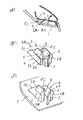
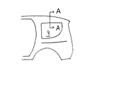
以下、本発明の実施例を図面に基づいて説明する。図1(A)は本発明の取付部品固定構造の第1実施例を示すもので、図1(A)は要部断面図、図1(B)は係止爪の取付孔への挿入状態を示す斜視図、図1(C)はトリム部材に設けられた係止爪を示す斜視図、図2は車両後部の概略側面図、図3は本発明の取付部品固定構造の第2実施例を示す斜視図、図4は本発明の取付部品固定構造の第3実施例を示すもので、図4(A)は斜視図、図4(B)は要部拡大図、図5は本発明の取付部品固定構造の第4実施例を示すもので、図5(A)は斜視図、図5(B)は要部平面図、図6は本発明の取付部品固定構造の第5実施例を示すもので、図6(A)は斜視図、図6(B)は要部平面図である。 Embodiments of the present invention will be described below with reference to the drawings. FIG. 1 (A) shows a first embodiment of a mounting part fixing structure according to the present invention, FIG. 1 (A) is a cross-sectional view of the main part, and FIG. 1 (B) is an inserted state of a locking claw into a mounting hole. FIG. 1 (C) is a perspective view showing a locking claw provided on the trim member, FIG. 2 is a schematic side view of the rear portion of the vehicle, and FIG. 3 is a second embodiment of the mounting part fixing structure of the present invention. FIG. 4 shows a third embodiment of the mounting part fixing structure of the present invention, FIG. 4 (A) is a perspective view, FIG. 4 (B) is an enlarged view of the main part, and FIG. 5 is the present invention. FIG. 5 (A) is a perspective view, FIG. 5 (B) is a plan view of an essential part, and FIG. 6 is a fifth embodiment of the mounting part fixing structure of the present invention. 6A is a perspective view, and FIG. 6B is a plan view of the main part.
本発明の基本的な構造は、図1に示すように、取付部品であるトリム部材1に設けた係止爪5、6を車体パネル2等の取付孔3に挿入固定するように構成した取付部品固定構造において、抜止部5B、6Bを有する間隔変更自在な一対の係止爪5、6をトリム部材1に設けるとともに、これら一対の係止爪5、6間に進入可能な間隔保持部材7を係止爪5、6あるいはトリム部材1に揺動自在に設けたことを特徴とする。
As shown in FIG. 1, the basic structure of the present invention is an installation in which
実施例について以下に詳述する。図2は車体後部の側面図で、クォータウィンド9の近傍を示すもので、クォータウィンド9の上部のA−A断面図である図1(A)に示すように、車体パネル2(図示の例ではルーフパネルインナ)の取付孔3に内装材であるトリム部材1を取り付けるに当たり、トリム部材1に係止爪4を設ける。係止爪4は、図1(C)に示すように、プラスチック等からなるトリム部材1と同材の、比較的柔軟な可撓性のある一対の係止爪5、6から構成される。一対の係止爪5、6は所定の間隔を置いてほぼ平行に直立して並設され、その頭部は撓んで近接変形可能である。
Examples will be described in detail below. FIG. 2 is a side view of the rear part of the vehicle body and shows the vicinity of the quarter window 9. As shown in FIG. 1A, which is an AA cross-sectional view of the upper part of the quarter window 9, as shown in FIG. Then, when attaching the
各係止爪5、6の頭部にはそれぞれ傾斜面5A、6Aが、それらの下部には抜止部5B、6Bが形成される。各係止爪5、6の後部(図1(A)の矢印の前進側が前部)には後部傾斜面5C、6Cが形成され、係止爪5、6の取付孔3への整合作用を行う。つまり、取付孔3の前後方向(図1(A)の矢印の方向)の適当な位置に係止爪5、6が挿入されつつあるとき、後部傾斜面5C、6Cが取付孔3の後端縁に当接するので、係止爪5、6を前方に導くことができる。
Inclined
本実施例では、第2係止爪6の前面に片ヒンジ状の間隔保持部材7が一体に形成される。該間隔保持部材7は一対の係止爪5、6の間に揺動して進入し、これらと直交状態になったとき、適正にこれらの間の間隔を保持する(図1(B)点線)。そして、間隔保持部材7の直交状態を維持できるように、第1係止爪5の内側にはストッパ8が形成される。間隔保持部材7の第2係止爪6へのヒンジ部は薄肉部により構成される。好適には、間隔保持部材7が係止爪5、6間に進入して間隔保持がなされるときの先端側に薄肉部が形成されるとよい。間隔保持部材7の厚み全体が間隔保持に寄与できるからである。
In the present embodiment, a one-hinged
このように構成したので、図1(B)に示すように、トリム部材1に設けられ係止爪5、6を車体パネル1の係止孔3(一点鎖線)に挿入していくと、各係止爪5、6の後部傾斜面5C、6Cが係止孔3の後部縁3Rに当接して各係止爪5、6を前方に導きつつ上方へ移動させる。係止爪5、6がさらに前方かつ上方に移動すると、間隔保持部材7が取付孔3の前部縁3Fに当接し、点線で示すように強制的に揺動していき、係止爪5、6の間に進入する。このとき既に、各係止爪5、6の頭部は抜止部5B、6Bが取付孔3の上部に到達している。最終的に、間隔保持部材7は取付孔3の前部縁3Fとストッパ8との間にて揺動を規制され、直交状態にて係止爪5、6の間隔を保持するので、柔軟な素材にて構成された係止爪5、6であってももはや係止孔3から抜け落ちることはない。
Since it comprised in this way, as shown to FIG. 1 (B), when the latching
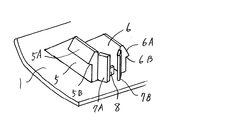
図3は本発明の取付部品固定構造の第2実施例を示す斜視図である。本実施例のものは、間隔保持部材7が両ヒンジ形式にて各係止爪5、6に設けられた例である。それぞれの係止爪5、6の前面に間隔保持部材7A、7Bが前記第1実施例のもののように薄肉部によりヒンジ結合される。図中の符号8は、取付部品であるトリム部材1から起立設置されたストッパである。かくして、それぞれの間隔保持部材7A、7Bのトロークを比較的小さくでき、トリム部材1等の取付部品の係止孔3に対する挿入程度に対して、係止爪5、6の間隔保持時期すなわちロック時期を早めることが可能となる。
FIG. 3 is a perspective view showing a second embodiment of the mounting component fixing structure of the present invention. The thing of a present Example is the example in which the space |
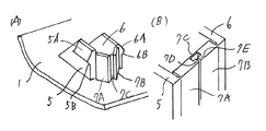
図4は本発明の取付部品固定構造の第3実施例を示すもので、図4(A)に示すように、本実施例のものも前記第2実施例のもののように、間隔保持部材7A、7Bが両ヒンジ形式にて各係止爪5、6に設けられたものであるが、本実施例では、これら間隔保持部材7A、7Bの対向面間を薄肉部7Cにより連結したものである。このような構成により、それぞれの間隔保持部材7A、7Bの揺動ストロークを比較的小さくして、係止爪5、6の間隔保持時期すなわちロック時期を早めることができるとともに、薄肉部7Cによる連結部が両ヒンジ形式の各間隔保持部材7A、7Bの揺動角度を同期させ、一対の係止爪5、6の間隔保持を均等に行える。
FIG. 4 shows a third embodiment of the mounting part fixing structure according to the present invention. As shown in FIG. 4A, the distance holding member 7A is the same as that of the second embodiment as shown in FIG. , 7B are provided on the
また、図4(B)に示すように、前記薄肉部7Cをトリム1の挿入進行方向の後部に形成した場合に、該肉部7Cの前方側の間隔保持部材7A、7Bの対向面にそれぞれ突起7D、7Eを形成することによって、間隔保持部材7A、7Bのそれ以上の後方への揺動が規制され、ストッパ機能を有するので、別途の格別のストッパを設ける必要がなくなる。
Further, as shown in FIG. 4B, when the thin portion 7C is formed at the rear portion in the direction in which the
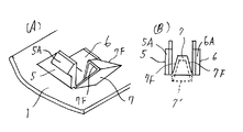
図5は本発明の取付部品固定構造の第4実施例を示すもので、図5(A)に示すように、間隔保持部材7が傾斜辺7F、7Fを有するボックス状体から構成された例である。図示の例では側面視で三角形状を呈し、その下端部がトリム部材1に揺動自在にヒンジ結合されている。水平ヒンジ形態であるが、前述実施例のように、係止爪5、6の一方の前面に鉛直軸にてヒンジ結合されてもよい(この場合には、三角形の一面が徐々に間隔保持を行う)ことは言うまでもない。図5(B)に示すように、ボックス状の間隔保持部材7の上面は係止爪5、6側が狭い傾斜面7E、7Eとされる。後面はその狭い幅のままでヒンジ部に接続される。トリム部材1の前進にしたがって、間隔保持部材7は点線位置7’から係止爪5、6間に進入して実線位置7に至る。このような構成により、比較的強固な構造のボックス状体により一対の係止爪5、6の間隔保持を確実に行える。しかも、傾斜辺7Fの存在により、急激な間隔保持ロックではなく、強制的ではあるが徐々に間隔保持を行えて、間隔保持部材7による係止爪5、6の前面への衝撃負担を軽減させることができる。
FIG. 5 shows a fourth embodiment of the mounting part fixing structure of the present invention. As shown in FIG. 5 (A), an example in which the
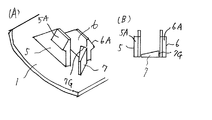
図6は本発明の取付部品固定構造の第5実施例を示すもので、本実施例のものは間隔保持部材の形状を工夫することで、間隔保持機能とストッパ機能を向上させた例である。図6(A)に示すように、本実施例の間隔保持部材7の平面形状を略三角形に構成したものである。薄肉ヒンジ部を間隔保持部材7の直交ロック時(間隔保持時)の前面側とし、直交ロック時に三角形の底辺側を第2係止爪6の内側に当接するようにした。このように構成することにより、図6(B)に示すように、直交ロック時には、間隔保持部材7の三角形の底辺7G側が第2係止爪6の内側に当接して、間隔保持部材7のそれ以上の後方側への揺動を確実に規制するとともに、係止爪5、6が近接しようとする力に対して、三角形の広い底辺7G側に分散して充分に抗することができ、高い間隔保持機能を発揮する。
FIG. 6 shows a fifth embodiment of the mounting part fixing structure according to the present invention, which is an example in which the interval holding function and the stopper function are improved by devising the shape of the interval holding member. . As shown in FIG. 6 (A), the planar shape of the spacing
以上、本発明の各実施の形態について説明してきたが、本発明の趣旨の範囲内で、トリム部材等の取付部品の種類(トリム部材の取付固定に限定されずに、各種取付部品の固定に適用され得る)、車体パネル等の被取付部材の種類(車体パネルに限定されず、トリム部材にさらに取付部品を固定する際にも使用できる)、傾斜面および後部傾斜面ならびに抜止部の形状を含む係止爪の形状(傾斜面各部の角度等)、形式およびその取付部品であるトリム部材への設置形態(トリム部材と一体成形同材の他、別体の係止爪を適宜の形態にてトリム部材等の取付部品に設置することもできる)、車体パネル等の取付孔の形状、間隔保持部材の形状(係止爪間の前面空間全てを塞ぐ大きさの他、間隔保持が可能であれば高さの低いものでもよい。また、ボックス形状も側面視で三角形状の他、菱形等適宜の形状が採用され得る)、形式およびヒンジ形式(係止爪と一体成形の薄肉部によるヒンジ形式の他、適宜の方式により係止爪や取付部品に設置してもよい。片ヒンジおよび両ヒンジ形式等)、間隔保持部材の対向面間の薄肉部の長さ(一対の間隔保持部材が所定角度前方に拡開可能な長さとされる)、ストッパの形状、形式およびその設置部位(係止爪の内面、トリム部材の上面等、また両ヒンジ形式の間隔保持部材の対向面間に突起を形成したり、間隔保持部材の三角形状の底辺にスットパ機能を持たせる等)等については適宜選定することができる。 The embodiments of the present invention have been described above. However, within the scope of the present invention, the types of mounting parts such as trim members (not limited to mounting and fixing trim members) Applicable), types of mounted members such as vehicle body panels (not limited to vehicle body panels, can also be used when fixing mounting parts to trim members), shapes of inclined surfaces, rear inclined surfaces and retaining portions Including the shape of the locking claw (angle of each part of the inclined surface, etc.), the type and the installation form to the trim member that is the mounting part (in addition to the same material integrally molded with the trim member) It can also be installed on mounting parts such as trim members), the shape of the mounting holes in the body panel, etc., the shape of the spacing member (the size that covers all the front space between the locking claws, and the spacing can be maintained) If it is, it can be low. In addition to the triangular shape in the side view, an appropriate shape such as a rhombus may be adopted), the form and the hinge form (in addition to the hinge form by the thin part integrally formed with the engaging claw, the engaging claw by an appropriate method) It may be installed on a mounting part, such as a single hinge or a type of both hinges), and the length of the thin portion between the opposing surfaces of the spacing member (the length of the pair of spacing members can be expanded forward by a predetermined angle). ), The shape and type of the stopper, and the location of the stopper (the inner surface of the locking claw, the upper surface of the trim member, etc., and a protrusion between the opposing surfaces of both hinge-type spacing members, or the triangular shape of the spacing members. Etc.) can be appropriately selected.
1 取付部品(トリム部材等)
2 車体パネル
3 取付孔
3F 前部縁
3R 後部縁
4 係止爪
5 第1係止爪
5A 傾斜面
5B 抜止部
5C 後部傾斜面
6 第2係止爪
6A 傾斜面
6B 抜止部
6C 後部傾斜面
7 間隔保持部材
7A 第1間隔保持部材
7B 第2間隔保持部材
7C 薄肉部
7D 第1突起
7E 第2突起
7F 傾斜辺
7G ストッパ(底辺)
8 ストッパ
9 クォータウィンド
1 Mounting parts (trim members, etc.)
2
8 Stopper 9 Quarter window
Claims (6)
The mounting part fixing structure according to any one of claims 1 to 5, further comprising a stopper capable of maintaining the spacing member in a state substantially orthogonal to the locking claw.
Priority Applications (1)
| Application Number | Priority Date | Filing Date | Title |
|---|---|---|---|
| JP2004315114A JP2006123739A (en) | 2004-10-29 | 2004-10-29 | Mounting parts fixing structure |
Applications Claiming Priority (1)
| Application Number | Priority Date | Filing Date | Title |
|---|---|---|---|
| JP2004315114A JP2006123739A (en) | 2004-10-29 | 2004-10-29 | Mounting parts fixing structure |
Publications (1)
| Publication Number | Publication Date |
|---|---|
| JP2006123739A true JP2006123739A (en) | 2006-05-18 |
Family
ID=36718878
Family Applications (1)
| Application Number | Title | Priority Date | Filing Date |
|---|---|---|---|
| JP2004315114A Withdrawn JP2006123739A (en) | 2004-10-29 | 2004-10-29 | Mounting parts fixing structure |
Country Status (1)
| Country | Link |
|---|---|
| JP (1) | JP2006123739A (en) |
Cited By (2)
| Publication number | Priority date | Publication date | Assignee | Title |
|---|---|---|---|---|
| JP2007315534A (en) * | 2006-05-26 | 2007-12-06 | Kai R & D Center Co Ltd | Connector |
| JP2014214784A (en) * | 2013-04-24 | 2014-11-17 | 日本発條株式会社 | Insertion member |
-
2004
- 2004-10-29 JP JP2004315114A patent/JP2006123739A/en not_active Withdrawn
Cited By (2)
| Publication number | Priority date | Publication date | Assignee | Title |
|---|---|---|---|---|
| JP2007315534A (en) * | 2006-05-26 | 2007-12-06 | Kai R & D Center Co Ltd | Connector |
| JP2014214784A (en) * | 2013-04-24 | 2014-11-17 | 日本発條株式会社 | Insertion member |
Similar Documents
| Publication | Publication Date | Title |
|---|---|---|
| EP4541663B1 (en) | Attaching member, combination of attaching member and attached member, and vehicle | |
| EP2199629B1 (en) | Anchor | |
| JP6712631B2 (en) | Slide rail mechanism and its bracket device | |
| JP6762986B2 (en) | Interior cover mounting structure | |
| JP3576147B2 (en) | Sunshade attachment | |
| CN103991367A (en) | Vehicle door structure | |
| EP2489887B1 (en) | Attachment structure and attachment tool | |
| JPH06270673A (en) | Clip mounting seat | |
| JP2001347895A (en) | Monitor mounting structure | |
| JP6775445B2 (en) | Instrument panel structure | |
| JP7117257B2 (en) | Mounting structure of vehicle decorative panel | |
| JP6315186B2 (en) | Pull pocket mounting structure | |
| JP5176313B2 (en) | Vehicle seat | |
| JP4919835B2 (en) | Door lock bracket | |
| JP7600911B2 (en) | Pull handle cap mounting structure | |
| JP2020117138A (en) | Storage console | |
| JP5152864B2 (en) | Slide door speaker arrangement structure | |
| JP4309156B2 (en) | Fastener | |
| JPH09267700A (en) | Pantograph type jack holding device | |
| JP4214823B2 (en) | Temporary holding structure for suspended rear cooler | |
| JPH0743291Y2 (en) | Expansion joints | |
| JP7067427B2 (en) | Vehicle structure | |
| JP2005042496A (en) | Mounting bracket for outer wall material, wall surface structure using the same, and construction method thereof | |
| JP4047519B2 (en) | Panel mounting bracket | |
| JP3941318B2 (en) | Decorative plate construction structure |
Legal Events
| Date | Code | Title | Description |
|---|---|---|---|
| A300 | Withdrawal of application because of no request for examination |
Free format text: JAPANESE INTERMEDIATE CODE: A300 Effective date: 20080108 |