JP2006123799A - Rear bumper structure - Google Patents
Rear bumper structure Download PDFInfo
- Publication number
- JP2006123799A JP2006123799A JP2004316149A JP2004316149A JP2006123799A JP 2006123799 A JP2006123799 A JP 2006123799A JP 2004316149 A JP2004316149 A JP 2004316149A JP 2004316149 A JP2004316149 A JP 2004316149A JP 2006123799 A JP2006123799 A JP 2006123799A
- Authority
- JP
- Japan
- Prior art keywords
- opening
- vehicle
- rear bumper
- folded
- lid
- Prior art date
- Legal status (The legal status is an assumption and is not a legal conclusion. Google has not performed a legal analysis and makes no representation as to the accuracy of the status listed.)
- Pending
Links
- 238000001746 injection moulding Methods 0.000 description 2
- 241000270728 Alligator Species 0.000 description 1
- 238000010586 diagram Methods 0.000 description 1
- 230000037431 insertion Effects 0.000 description 1
- 238000003780 insertion Methods 0.000 description 1
- 239000002184 metal Substances 0.000 description 1
Images
Landscapes
- Body Structure For Vehicles (AREA)
Abstract
Description
本発明は、車両の後部に設けられたリアバンパ構造に関する。 The present invention relates to a rear bumper structure provided at a rear portion of a vehicle.
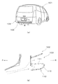
従来、図3の(a)に示すように、車両101の後端部には、リアバンパ102が設けられており、該リアバンパ102には、ダウンフォース用の開口部103が設けられている。
Conventionally, as shown in FIG. 3A, a
これにより、図3の(b)に示すように、走行時に発生する空気の流れを前記開口部103を通過させることで、走行抵抗を低減するとともに、下方へ向けた力を発生させて揚力の低減を図ることができるように構成されており、走行安定性の向上に寄与している。
As a result, as shown in FIG. 3B, the flow of air generated during traveling is allowed to pass through the
このリアバンパ102は、金型によって樹脂成形されており、前記開口部103の下部には、前記開口部103の下縁を構成する棚面111と、該棚面111の後縁より下方へ屈曲した後、車両前方Fへ折り返した折返し部112とによって、型抜き方向である車両前方Fへ向けて開口した断面コ字状の前記前方開口形状部113が形成されている。これにより、所定の剛性が確保されている。
The
しかしながら、このようなリアバンパ102にあっては、走行時の空気が流れる開口部103の下部の前方開口形状部113が断面コ字状に形成されており、車両前方Fへ向けて開口した袋形状を成している。
However, in such a
このため、走行時に流れる空気が前記前方開口形状部113内で滞留し、この部分の空気を車両後方Rへスムーズに流すことができないという問題があった。
For this reason, there is a problem that the air that flows during traveling stays in the front
本発明は、このような従来の課題に鑑みてなされたものであり、空力特性のさらなる向上を図ることができるリアバンパ構造を提供することを目的とするものである。 The present invention has been made in view of such a conventional problem, and an object of the present invention is to provide a rear bumper structure capable of further improving aerodynamic characteristics.
前記課題を解決するために本発明のリアバンパ構造にあっては、リアバンパにダウンフォース用の開口部が設けられ、該開口部の下部に、当該開口部の下縁を構成する車両前後方向に延在した棚面と、該棚面の後縁より下方へ屈曲した後車両前方へ折り返した折返し部とが形成され、該折返し部と前記棚面とで車両前方へ向けて開口した断面形状の前方開口形状部が前記開口部の下部に形成されたリアバンパ構造において、前記折返し部の前端に薄肉のヒンジ部を介して蓋部を一体形成し、該蓋部が前記折返し部より下方に延出した展開状態と、前記ヒンジ部を中心に折り曲げて前記蓋部の先端を前記棚面の前端に当接又は近接させて前記前方開口形状部の開口部分を閉鎖した閉鎖状態とを形成可能に構成するとともに、前記蓋部の先端に、前記閉鎖状態にて当該リアバンパに固定される固定部を設けた。 In order to solve the above problems, in the rear bumper structure of the present invention, the rear bumper is provided with an opening for downforce, and extends below the opening in the vehicle front-rear direction constituting the lower edge of the opening. A front side of a cross-sectional shape that is formed toward the front of the vehicle by the folded back part and the shelf surface. In the rear bumper structure in which the opening shape portion is formed in the lower portion of the opening portion, a lid portion is integrally formed at the front end of the folded portion via a thin hinge portion, and the lid portion extends downward from the folded portion. An unfolded state and a closed state in which the opening portion of the front opening shape portion is closed by folding the hinge portion as a center and bringing the front end of the lid portion into contact with or close to the front end of the shelf surface are configured. And at the tip of the lid, At serial closed provided the fixed portion fixed to the rear bumper.
すなわち、リアバンパに設けられた開口部の下部には、該開口部の下縁を構成する棚面と該棚面の後縁に連設された折返し部とによって車両前方へ向けて開口した断面形状の前方開口形状部が形成されており、走行時に流れる空気が、この前方開口形状部内で滞留し、車両後方へスムーズな流れが阻害される。 That is, at the lower part of the opening provided in the rear bumper, a cross-sectional shape that opens toward the front of the vehicle by a shelf surface that constitutes the lower edge of the opening and a folded portion that is continuous with the rear edge of the shelf surface The front opening shape portion is formed, and air flowing during traveling stays in the front opening shape portion, and a smooth flow is hindered to the rear of the vehicle.
しかし、前記折返し部には、ヒンジ部を介して蓋部が一体形成されており、前記ヒンジ部を中心に折り曲げて前記蓋部の先端を前記棚面の前端に当接又は近接させることによって、前記前方開口形状部の開口部分が閉鎖された閉鎖状態が形成される。このとき、前記蓋部に設けられた固定部を、当該リアバンパに固定することによって、前記閉鎖状態が維持される。 However, the folded portion is integrally formed with a lid portion via a hinge portion, and is bent around the hinge portion to bring the tip of the lid portion into contact with or close to the front end of the shelf surface. A closed state in which the opening portion of the front opening shape portion is closed is formed. At this time, the said closed state is maintained by fixing the fixing | fixed part provided in the said cover part to the said rear bumper.
一方、前記蓋部は、前記ヒンジ部を介して前記折返し部に連設されており、前記蓋部を前記折返し部より下方に延出することによって、前記前方開口形状部の開口部分が開放された展開状態が形成される。 On the other hand, the lid portion is connected to the folded portion via the hinge portion, and the opening portion of the front opening shape portion is opened by extending the lid portion below the folded portion. A developed state is formed.
以上説明したように本発明のリアバンパ構造にあっては、リアバンパの開口部の下部に設けられた前方開口形状部の開口部分を蓋部で閉鎖した閉鎖状態を形成することができる。このため、走行時の空気をスムーズに車両後方へ流すことができる。 As described above, in the rear bumper structure of the present invention, it is possible to form a closed state in which the opening portion of the front opening shape portion provided at the lower portion of the opening portion of the rear bumper is closed by the lid portion. For this reason, the air at the time of driving | running | working can be smoothly flowed to vehicle back.
したがって、走行時に車両後方へ流れる空気が、ダウンフォース用の開口部下部に形成された前方開口形状部の開口部分で滞留する従来と比較して、空気の流れを改善し空力特性のさらなる向上を図ることができる。 Therefore, the air flowing toward the rear of the vehicle during traveling stays at the opening portion of the front opening shape portion formed in the lower portion of the opening portion for downforce, improving the air flow and further improving the aerodynamic characteristics. Can be planned.
そして、前記蓋部は、薄肉のヒンジ部を介して前記前方開口形状部を構成する折返し部に連設されており、前記蓋部を前記折返し部より下方に延出することによって、前記前方開口形状部の開口部分が開放された展開状態を形成することができる。 And the said cover part is provided in a row by the folding part which comprises the said front opening shape part via the thin hinge part, and the said front opening is extended by extending the said cover part below from the said folding part. An unfolded state in which the opening portion of the shape portion is opened can be formed.
これにより、前記前方開口形状部の開口部分を閉鎖する前記蓋部を、スライド型を用いることなく、当該リアバンパに一体形成することができる。このため、閉断面形状の形成が困難なインジェクション成形の採用が可能となる。 Thereby, the said cover part which closes the opening part of the said front opening shape part can be integrally formed in the said rear bumper, without using a slide type | mold. For this reason, it is possible to employ injection molding in which it is difficult to form a closed cross-sectional shape.
そして、ブロー成形した別部品を用いること無く、使用時には前記前方開口形状部の開口部分が閉鎖されたリアバンパを形成することができる。したがって、低コスト化を図ることができる。 And the rear bumper by which the opening part of the said front opening shape part was closed at the time of use can be formed, without using another blow molded part. Therefore, cost reduction can be achieved.
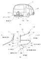
以下、本発明の一実施の形態を図に従って説明する。図1は、本実施の形態にかかるリアバンパ構造を備えた車両1を示す図である。
Hereinafter, an embodiment of the present invention will be described with reference to the drawings. FIG. 1 is a diagram showing a
すなわち、この車両1の車体11の後端下部には、図1の(b)にも示すように、リアバンパ12が設けられており、該リアバンパ12の車幅方向に延在するバンパ本体13の両端部には、車両1の側面に沿って車両前方Fへ向けて湾曲した湾曲部14,14が形成されている。このリアバンパ12は、金型によって樹脂成形されており、型抜き方向が、取付状態における車両前方F側及び車両後方R側に設定されている。
That is, a
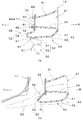
前記リアバンパ12の前記バンパ本体13には、ダウンフォース用の開口部21が車幅方向に延設されており、図2にも示すように、走行時に発生する空気の流れ22が前記開口部21を通過することで、走行抵抗を低減するとともに、下方へ向けた力を発生させて揚力の低減を図り、走行安定性の向上に寄与できるように構成されている。
The
前記開口部21の開口縁からは、図1の(b)に示したように、車両前方Fへ向けて延出するフランジ31が全周縁に渡って形成されており、該フランジ31からは、図2の(a)に示すように、突起32,32が複数箇所に突設されている。該突起32は、金網33を挿通するように構成されており、当該フランジ31の前端には、前記開口部21を覆う前記金網33が支持されている。前記フランジ31は、型抜き方向に延在しており、前記開口部21の下縁には、車両前後方向に延在する棚面34が前記フランジ31によって構成されている。
From the opening edge of the opening 21, as shown in FIG. 1B, a
この棚面34の車両後方R側の後縁には、図1の(b)に示すように、下方へ向けて延出するとともに車両前方F側へ向けて湾曲した湾曲部41が一体形成されており、該湾曲部41の先端には、車両前方Fへ向けて延出する前方延出面42が一体形成されている。この前方延出面42と前記湾曲部41とによって、前記棚面34より下方へ屈曲した後、車両前方F側へ折り返した折返し部43が前記開口部21の下部に形成されており、該折返し部43と前記棚面34とによって、前記型抜き方向である車両前方Fへ向けて開口した断面コ字形状の前方開口形状部44が形成され、当該リアバンパ12の剛性が高められている。
As shown in FIG. 1B, a
前記折返し部43の前端には、薄肉のヒンジ部51(PPヒンジ)を介して蓋部52が一体形成されており、該蓋部52は、図1の(b)中実線で示したように、前記折返し部43より下方に延出した展開状態53と、図中破線で示したように、前記ヒンジ部51を中心に上方へ折り曲げて前記蓋部52の自由端部である先端を前記棚面34の前端に当接又は近接させ前記前方開口形状部44の前方開口部54を閉鎖した閉鎖状態55とを任意に形成できるように構成されている。
A
この蓋部52は、前記閉鎖状態55において、前記折返し部43の前記前方延出面42の延長上に配置される前方延長部61と、該前方延長部61より斜め後方へ屈曲して延出した傾斜部62とによって断面く字状に形成されている。この傾斜部62は、その先端が前記棚面34前部に当接又は近接した状態で固定されるように構成されており、当該傾斜部62は、走行時に車両前方Fから車両後方Rに向けて流れる空気を前記開口部21に案内するガイドを構成していいる。
In the closed
前記蓋部52の先端には、図2の(a)に示すように、前記閉鎖状態55にて当該リアバンパに12固定される固定部71が複数箇所に設けられている。この固定部71は、前記閉鎖状態55において前記傾斜部62より上方に延出した延出片からなり、当該固定部71は、前記金網33に沿って延在するように構成されている。
As shown in FIG. 2A, a plurality of
前記固定部71には、前記金網33を支持する前記突起32が挿入される挿入穴81が設けられており、前記突起32には、ワニ口クリップ82が設けられている。これにより、当該蓋部52は、前記固定部71が前記金網33と共にリアバンパ12を構成する前記フランジ31に固定されており、前記閉鎖状態55が維持されている。
The
以上の構成にかかる本実施の形態において、リアバンパ12に設けられた開口部21の下部には、該開口部21の下縁を構成する棚面34と該棚面34の後縁に連設された折返し部43とによって車両前方Fへ向けて開口した断面形状の前方開口形状部44が形成されており、走行時の空気の流れ22が、この前方開口形状部44内で滞留し、車両後方Rへスムーズな流れが阻害される恐れがある。
In the present embodiment having the above-described configuration, the lower portion of the
しかし、本実施の形態にあっては、前記折返し部43にヒンジ部51を介して蓋部52が一体形成されており、前記ヒンジ部51を中心に折り曲げて前記蓋部52の先端を前記棚面34の前端に当接又は近接させることによって、前記前方開口形状部44の前方開口部54が閉鎖された閉鎖状態55を形成することができる。このとき、前記蓋部52に設けられた固定部71を、当該リアバンパ12に固定することによって、前記閉鎖状態55を維持することができる。
However, in the present embodiment, a
このため、走行時の空気をスムーズに車両後方Rへ流すことができる。よって、走行時に車両後方Rへ流れる空気が、ダウンフォース用の開口部21下部に形成された前方開口形状部44の前方開口部54で滞留する従来と比較して、空気の流れを改善し空力特性のさらなる向上を図ることができる。
For this reason, the air at the time of driving | running | working can be smoothly flowed to vehicle back R. FIG. Therefore, the air flowing toward the rear R of the vehicle at the time of traveling improves the air flow and aerodynamics as compared to the conventional case where the air stays at the
そして、前記蓋部52は、前記ヒンジ部51を介して前記折返し部43に連設されており、前記蓋部52を前記折返し部43より下方に延出することによって、前記前方開口形状部44の前方開口部54が開放された展開状態53を形成することができる。
The
これにより、前記前方開口形状部44の前方開口部54を閉鎖する前記蓋部52を、スライド型を用いることなく、当該リアバンパ12に一体形成することができる。このため、閉断面形状の形成が困難なインジェクション成形の採用が可能となる。
Thereby, the said
また、ブロー成形した別部品を用いること無く、使用時には前記前方開口形状部44の前方開口部54が閉鎖されたリアバンパ12を形成することができる。したがって、低コスト化を図ることができる。
In addition, the
12 リアバンパ
21 開口部
34 棚面
43 折返し部
44 前方開口形状部
51 ヒンジ部
52 蓋部
53 展開状態
55 閉鎖状態
71 固定部
12
Claims (1)
前記折返し部の前端に薄肉のヒンジ部を介して蓋部を一体形成し、該蓋部が前記折返し部より下方に延出した展開状態と、前記ヒンジ部を中心に折り曲げて前記蓋部の先端を前記棚面の前端に当接又は近接させて前記前方開口形状部の開口部分を閉鎖した閉鎖状態とを形成可能に構成するとともに、前記蓋部の先端に、前記閉鎖状態にて当該リアバンパに固定される固定部を設けたことを特徴とするリアバンパ構造。
The rear bumper is provided with an opening for downforce, and at the lower part of the opening is a shelf surface extending in the vehicle front-rear direction constituting the lower edge of the opening and bent downward from the rear edge of the shelf surface. In a rear bumper structure in which a folded portion that is folded back to the front of the rear vehicle is formed, and a front opening shape portion having a cross-sectional shape that opens toward the front of the vehicle at the folded portion and the shelf surface is formed at a lower portion of the opening,
A lid portion is integrally formed at the front end of the folded portion via a thin hinge portion, the lid portion extends downward from the folded portion, and the distal end of the lid portion is bent around the hinge portion. Is closed to the front end of the shelf surface so as to form a closed state in which the opening portion of the front opening shape portion is closed, and the rear bumper is attached to the tip of the lid portion in the closed state. A rear bumper structure characterized by providing a fixed portion to be fixed.
Priority Applications (1)
| Application Number | Priority Date | Filing Date | Title |
|---|---|---|---|
| JP2004316149A JP2006123799A (en) | 2004-10-29 | 2004-10-29 | Rear bumper structure |
Applications Claiming Priority (1)
| Application Number | Priority Date | Filing Date | Title |
|---|---|---|---|
| JP2004316149A JP2006123799A (en) | 2004-10-29 | 2004-10-29 | Rear bumper structure |
Publications (1)
| Publication Number | Publication Date |
|---|---|
| JP2006123799A true JP2006123799A (en) | 2006-05-18 |
Family
ID=36718927
Family Applications (1)
| Application Number | Title | Priority Date | Filing Date |
|---|---|---|---|
| JP2004316149A Pending JP2006123799A (en) | 2004-10-29 | 2004-10-29 | Rear bumper structure |
Country Status (1)
| Country | Link |
|---|---|
| JP (1) | JP2006123799A (en) |
Citations (3)
| Publication number | Priority date | Publication date | Assignee | Title |
|---|---|---|---|---|
| JPH04274945A (en) * | 1991-02-28 | 1992-09-30 | Nishikawa Kasei Co Ltd | Bumper structure |
| JPH055677U (en) * | 1991-03-11 | 1993-01-26 | 西川化成株式会社 | Bumper structure |
| JP2002036982A (en) * | 2000-07-26 | 2002-02-06 | Nishikawa Kasei Co Ltd | Vehicle bumper fascia |
-
2004
- 2004-10-29 JP JP2004316149A patent/JP2006123799A/en active Pending
Patent Citations (3)
| Publication number | Priority date | Publication date | Assignee | Title |
|---|---|---|---|---|
| JPH04274945A (en) * | 1991-02-28 | 1992-09-30 | Nishikawa Kasei Co Ltd | Bumper structure |
| JPH055677U (en) * | 1991-03-11 | 1993-01-26 | 西川化成株式会社 | Bumper structure |
| JP2002036982A (en) * | 2000-07-26 | 2002-02-06 | Nishikawa Kasei Co Ltd | Vehicle bumper fascia |
Similar Documents
| Publication | Publication Date | Title |
|---|---|---|
| JP4487935B2 (en) | Aerodynamic equipment for vehicles | |
| JP2005212777A (en) | Automobile provided with air guide device | |
| JP6644977B2 (en) | Aerodynamic components | |
| US6227613B1 (en) | Vehicle with a sliding fabric roof and a front spoiler thereon | |
| JP2006123799A (en) | Rear bumper structure | |
| JP6684560B2 (en) | Vehicle wind noise reduction structure | |
| JP6621635B2 (en) | Wind noise reduction structure for vehicles | |
| JP2009107446A (en) | Side step molding for vehicles | |
| JP4489722B2 (en) | Vehicle side structure | |
| JP6597741B2 (en) | Vehicle exterior structure | |
| JP7671025B2 (en) | Vehicle side visors | |
| JP2017081444A (en) | Vehicle structure | |
| JP6191550B2 (en) | Aerodynamic structure for vehicles | |
| JP2005178769A (en) | Wind deflector and open roof construction provided therewith | |
| JP3210360U (en) | Rear spoiler | |
| JP4654576B2 (en) | Automotive bumper structure | |
| JP6127158B2 (en) | Vehicle sunroof structure | |
| JP6634253B2 (en) | Vehicle wind noise reduction structure | |
| JP2000233643A (en) | Car sunroof deflector | |
| JP5440791B2 (en) | Car with wind deflector | |
| JP2019119335A (en) | Deflector device of vehicle | |
| JPH0230388Y2 (en) | ||
| JP2008543635A (en) | Wind deflector for sliding roof | |
| JP2020083108A (en) | Vehicle front structure | |
| JP3624093B2 (en) | Handle structure of opener device |
Legal Events
| Date | Code | Title | Description |
|---|---|---|---|
| A621 | Written request for application examination |
Effective date: 20070727 Free format text: JAPANESE INTERMEDIATE CODE: A621 |
|
| A977 | Report on retrieval |
Free format text: JAPANESE INTERMEDIATE CODE: A971007 Effective date: 20091210 |
|
| A131 | Notification of reasons for refusal |
Free format text: JAPANESE INTERMEDIATE CODE: A131 Effective date: 20091222 |
|
| A02 | Decision of refusal |
Free format text: JAPANESE INTERMEDIATE CODE: A02 Effective date: 20100608 |