JP2006163473A - Caring driving guide device and caring driving guide method - Google Patents
Caring driving guide device and caring driving guide method Download PDFInfo
- Publication number
- JP2006163473A JP2006163473A JP2004349507A JP2004349507A JP2006163473A JP 2006163473 A JP2006163473 A JP 2006163473A JP 2004349507 A JP2004349507 A JP 2004349507A JP 2004349507 A JP2004349507 A JP 2004349507A JP 2006163473 A JP2006163473 A JP 2006163473A
- Authority
- JP
- Japan
- Prior art keywords
- passenger
- driving state
- driving
- driver
- caring
- Prior art date
- Legal status (The legal status is an assumption and is not a legal conclusion. Google has not performed a legal analysis and makes no representation as to the accuracy of the status listed.)
- Granted
Links
Images








Landscapes
- Traffic Control Systems (AREA)
Abstract
【課題】 同乗者が快適と感じる運転操作を運転者に対してガイドする気遣い運転ガイド装置および気遣い運転ガイド方法を提供する。
【解決手段】 急ブレーキ度算出判定部9によって急ブレーキ度不快判定を、スピード出し過ぎ度算出判定部10によってスピード出し過ぎ度不快判定を、狭い車間距離度算出判定部11によって狭い車間距離不快判定を行い、同乗者不快度算出部12において同乗者にとって不快な運転状態を検出し、表示部3を通じて運転者に報知することによって、同乗者の感じている不快感を運転者に直接伝えて、運転操作の修正を促すことができる。
【選択図】 図1PROBLEM TO BE SOLVED: To provide a caring driving guide device and a caring driving guide method for guiding a driving operation that a passenger feels comfortable to the driver.
SOLUTION: Sudden braking degree calculation determination unit 9 performs sudden braking degree discomfort determination, overspeeding degree calculation determination unit 10 determines excessive speed discomfort determination, and narrow inter-vehicle distance degree calculation determination unit 11 determines narrow inter-vehicle distance discomfort determination. The passenger discomfort calculation unit 12 detects a driving state that is uncomfortable for the passenger, and notifies the driver through the display unit 3 so that the driver feels the discomfort felt by the passenger directly. It is possible to urge correction of driving operation.
[Selection] Figure 1
Description
本発明は、同乗者にとって不快な運転状態を検出して運転者に報知する気遣い運転ガイド装置および気遣い運転ガイド方法に関する。 The present invention relates to a caring driving guide device and a caring driving guide method for detecting a driving state uncomfortable for a passenger and notifying the driver.
従来、同乗者の有無に応じて車両の加速度合いを適正に補正する装置が特開平8−337133号公報に記載されている。
幼児もしくは老人、体の不自由な人を同乗させるときなど、同乗者への配慮が特に必要とされる場合には、運転者はアクセル操作が乱雑にならないように大変気を使う。そして運転者と同乗者とでも車両の加速度に対する不快感は異なるのが一般的である。そのため、上記装置は同乗者の有無に応じてその加速度合いを適正に制御しようとするものである。
When caring for passengers, such as when infants, elderly people, and people with reduced mobility are required, the driver is very careful not to disturb the accelerator operation. In general, the driver and passengers have different discomfort with respect to the acceleration of the vehicle. For this reason, the above apparatus attempts to appropriately control the acceleration according to the presence or absence of a passenger.
しかしながら、この従来の装置においては、オンタイムの加速度情報を運転者に提示し、急激な加速をしないように促すが、加速度情報だけでは同乗者の不快感を表現する指標としては不十分である。
さらに、運転者は自分の運転操作のどの部分に対して同乗者が不快感を感じているのかを認識しない限り、同乗者が不快感を感じないように運転傾向を改善するといったことは困難である。したがって、運転傾向の改善のために同乗者が不快と感じた運転操作を運転者に的確に伝達する必要があるが、従来の装置においてはこれに対応できないといった問題があった。
However, in this conventional apparatus, on-time acceleration information is presented to the driver and urged not to perform rapid acceleration, but the acceleration information alone is not sufficient as an index for expressing passenger discomfort. .
Furthermore, it is difficult for the driver to improve the driving tendency so that the passenger does not feel uncomfortable unless he / she recognizes what part of his / her driving operation he / she feels uncomfortable. is there. Therefore, in order to improve the driving tendency, it is necessary to accurately transmit the driving operation that the passenger feels uncomfortable to the driver, but there is a problem that the conventional apparatus cannot cope with this.
そこで本発明はこのような問題点に鑑み、同乗者が不快と感じる運転操作を運転者に報知し、同乗者が快適となるように運転操作のガイドを行う気遣い運転ガイド装置および気遣い運転ガイド方法を提供することを目的とする。 Therefore, in view of such problems, the present invention informs the driver of a driving operation that the passenger feels uncomfortable and guides the driving operation so as to make the passenger comfortable. The purpose is to provide.
本発明は、運転状態検出手段によって車両の運転状態を検出し、検出された運転状態にもとづいて同乗者不快感検出手段が同乗者にとって不快な運転状態であるかどうかを検出し、該検出結果を報知手段によって運転者に報知するものとした。 The present invention detects the driving state of the vehicle by the driving state detecting means, detects whether or not the passenger discomfort detecting means is an unpleasant driving state for the passenger based on the detected driving state, and the detection result To the driver by the notification means.
本発明によれば、同乗者が感じている不快感を報知手段を介して運転者に認識させることができるので、同乗者が不快感を感じないように運転傾向の修正を促すことができる。。 According to the present invention, it is possible to cause the driver to recognize the discomfort felt by the passenger via the notification means, so that it is possible to prompt the driver to correct the driving tendency so as not to feel the discomfort. .
次に本発明の実施の形態を実施例により説明する。
まず第1の実施例について説明する。
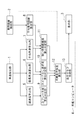
図1に、第1の実施例の全体構成を示す。
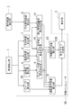
気遣い運転ガイド装置は、車速を検出する車速検出部1と、車間距離を検出する車間距離検出部2と、各種の処理を行う車載コンピュータ4と、車載コンピュータ4からの出力結果を表示する表示部3とより構成される。
車速検出部1は、たとえば車両の車輪速センサであり、車速に対応する車速値を車載コンピュータ4へ出力する。
車間距離検出部2は、たとえばオートクルーズ装置用のレーザレーダであり、車間距離に対応する車間距離信号を車載コンピュータ4へ出力する。
車載コンピュータ4は、後述の処理を行うことによって、運転者の操作において同乗者がどの操作に不快感を感じたかを示す画像を生成し、表示部3へ出力する。
Next, embodiments of the present invention will be described by way of examples.
First, the first embodiment will be described.
FIG. 1 shows the overall configuration of the first embodiment.
The caring driving guide device includes a vehicle
The vehicle
The inter-vehicle
The in-
車載コンピュータ4は、車速検出部1によって検出された車速値がそれぞれ入力される減速度算出部5、最高車速算出部6および平均車速算出部7を備え、さらに車間距離検出部2によって検出された車間距離信号が入力される平均車間距離算出部8を備える。
減速度算出部5は、車両の減速度を算出するものであり、最高車速算出部6は車両の最高車速を算出し、平均車速算出部7は車両の平均速度を算出する。また平均車間距離算出部8は、自車両と前方車両との車間距離の平均距離を算出する。
The in-
The
車載コンピュータ4はさらに、急ブレーキ度算出判定部9、スピード出し過ぎ度算出判定部10、狭い車間距離度算出判定部11を備える。
急ブレーキ度算出判定部9は、減速度算出部5によって算出された車両の減速度を用いて急ブレーキ度を算出し、該算出した急ブレーキ度にもとづいて同乗者にとって不快なブレーキ操作であるかどうかの判定を行う。
スピード出し過ぎ度算出判定部10は、最高車速算出部6によって算出された最高車速と平均車速算出部7によって算出された平均車速とを用いてスピード出し過ぎ度を算出し、該スピード出し過ぎ度にもとづいて同乗者にとって不快なスピードであるかどうかの判定を行う。
また狭い車間距離度算出判定部11は、平均車速算出部7によって算出された平均車速と平均車間距離算出部8によって算出された平均車間距離とを用いて、前方車両との車間距離が狭いかどうかをあらわす狭い車間距離度を算出し、該狭い車間距離度にもとづいて同乗者にとって不快な車間距離であるかどうかの判定を行う。
The in-
The sudden braking degree
The excessive speed
In addition, the narrow inter-vehicle distance degree
また車載コンピュータ4は、同乗者不快度算出部12および表示グラフ作成部13を備える。
同乗者不快度算出部12は、急ブレーキ度算出判定部9、スピード出し過ぎ度算出判定部10および狭い車間距離度算出判定部11の算出結果にもとづいて、同乗者の不快度を算出する。
表示グラフ作成部13は、同乗者不快度算出部12で算出された同乗者不快度を運転者に対して視覚的に提示するためのグラフを生成する。
この表示グラフ作成部13によって生成されたグラフが表示部3によって表示され、運転者に提示される。
The in-
The passenger discomfort
The display
The graph generated by the display
次に、気遣い運転ガイド処理について説明する。
図2は、気遣い運転ガイド処理の流れを示す図である。
ステップ100において車速検出部1は、車速の検出を行う。
ステップ101において減速度算出部5は、ステップ100で算出された車速をもとに、次の微分方程式を用いて減速度の算出を行う
A=dV/dt (1)
ここで、Aは減速度、Vは車速を表す。
Next, the caring driving guide process will be described.
FIG. 2 is a diagram illustrating the flow of the caring driving guide process.
In
In
Here, A represents deceleration and V represents vehicle speed.
ステップ102において最高車速算出部6は、ステップ100で算出された車速をもとに所定時間内での最高車速を算出し、ステップ103において平均車速算出部7は所定時間内での平均車速を算出する。
ステップ104において車間距離検出部2は、前方車両との車間距離の検出を行う。
ステップ105において平均車間距離算出部8は、ステップ104で検出された車間距離をもとに所定時間内での平均車間距離を算出する。
なお、ステップ104およびステップ105の処理は、後述のステップ106の処理を行う前であればいつ行ってもよく、たとえばステップ100〜ステップ103の処理の前に行うこともできる。
In
In
In
Note that the processing of
ステップ106において急ブレーキ度算出判定部9は、ステップ101で算出された車両の減速度をもとに、急ブレーキ度を次式を用いて算出する。
EB=A (2)
ここで、EBは急ブレーキ度、Aは減速度を表す。
なお本実施例においては、急ブレーキ度=減速度とする。
In
EB = A (2)
Here, EB represents the sudden braking degree, and A represents the deceleration.
In this embodiment, it is assumed that the sudden braking degree = deceleration.
ステップ107において急ブレーキ度算出判定部9は、算出した急ブレーキ度にもとづいて、ブレーキ操作が同乗者にとって不快であるかどうかの判定を行う。
減速度は、通常の減速時にも1.0〜4.5[m/s2]程度の大きさで発生していることが知られている。従って、4.5[m/s2]以内の大きさの減速度が発生する状態は通常の動作状態であると考えられる。
そこで本実施例では、急ブレーキ度の快適ゾーンを4.5[m/s2]以下とし、算出された急ブレーキ度が4.5[m/s2]を超える場合、急ブレーキ度算出判定部9は同乗者にとって不快な急ブレーキ度であると判定する。
ただし、急ブレーキ度の最大値が6.0[m/s2]以上である場合、緊急度が高い急ブレーキであると判断し安全性を優先して、同乗者にとって不快ではないと判定する。
In
It is known that the deceleration occurs at a magnitude of about 1.0 to 4.5 [m / s 2 ] even during normal deceleration. Therefore, it is considered that a state where a deceleration having a magnitude within 4.5 [m / s 2 ] is generated is a normal operation state.
Therefore, in this embodiment, when the comfortable zone of the sudden braking degree is 4.5 [m / s 2 ] or less and the calculated sudden braking degree exceeds 4.5 [m / s 2 ], the sudden braking degree calculation determination The
However, if the maximum value of the sudden braking degree is 6.0 [m / s 2 ] or more, it is determined that the emergency braking is a sudden braking with a high degree of urgency, and safety is prioritized and it is determined that the passenger is not uncomfortable. .
ステップ108においてスピード出し過ぎ度算出判定部10は、ステップ102で算出した最高車速と、ステップ103で算出した平均車速とをもとに、スピード出し過ぎ度を次式を用いて算出する。
OS=MS/AS (3)
ここで、OSはスピード出し過ぎ度、MSは最高車速(m/sec)、ASは平均車速(m/sec)を表す。
In
OS = MS / AS (3)
Here, OS represents the degree of excessive speed, MS represents the maximum vehicle speed (m / sec), and AS represents the average vehicle speed (m / sec).
ステップ109においてスピード出し過ぎ度算出判定部10は、算出したスピード出し過ぎ度にもとづいて、同乗者にとって不快なスピードであるかどうかの判定を行う。
車速は、通常の走行状態でも、平均車速に対して常に20%程度の変動はあると考えられ、この時の状態のスピード出し過ぎ度は、1.2となる。
そこで本実施例では、スピード出し過ぎ度の快適ゾーンを1.2以下とし、算出されたスピード出し過ぎ度の最大値が1.2を超える場合、スピード出し過ぎ度算出判定部10は同乗者にとって不快なスピードであると判定する。
ただし、発進直後や停止直前は車速の変動が大きいため、このような場合にはスピード出し過ぎ度の最大値が1.2を超えても、同乗者にとって不快ではないと判定する。
In
The vehicle speed is considered to always fluctuate by about 20% with respect to the average vehicle speed even in a normal traveling state, and the excessive speed in this state is 1.2.
Accordingly, in this embodiment, when the comfort zone of the overspeeding degree is set to 1.2 or less and the maximum value of the overspeeding degree calculated exceeds 1.2, the overspeeding degree
However, since the vehicle speed fluctuates immediately after starting or immediately before stopping, in such a case, it is determined that the passenger is not uncomfortable even if the maximum value of the overspeeding exceeds 1.2.
ステップ110において狭い車間距離度算出判定部11は、ステップ103で算出した平均車速と、ステップ105で算出した平均車間距離とをもとに狭い車間距離度を次式を用いて算出する。
SD=AS/AFD (4)
ここで、SDは狭い車間距離度、ASは平均車速(m/sec)、AFDは平均車間距離(m)を表す。
通常、人の平均的な反応時間は0.75秒とされている。
そこで本実施例では、反応時間が少ない場合(不快な場合)には値が大きくなるように、0.75の逆数(1.0/0.75=1.33)を演算し、1.33以下を車間距離度の快適ゾーンとする。
式(4)を用いて算出された狭い車間距離度が1.33を超える場合、同乗者にとって不快な狭い車間距離であると判定する。
ただし、発進直後や停止直前は、狭い車間距離度が1.33を超えても、同乗者にとって不快ではないと判定する。
In
SD = AS / AFD (4)
Here, SD represents a narrow inter-vehicle distance degree, AS represents an average vehicle speed (m / sec), and AFD represents an average inter-vehicle distance (m).
Usually, the average reaction time of a person is 0.75 seconds.
Therefore, in this embodiment, the reciprocal of 0.75 (1.0 / 0.75 = 1.33) is calculated so that the value becomes large when the reaction time is short (unpleasant), and 1.33 The following are the comfort zones for the distance between vehicles.
When the narrow inter-vehicle distance degree calculated by using the equation (4) exceeds 1.33, it is determined that the narrow inter-vehicle distance is uncomfortable for the passenger.
However, immediately after starting or immediately before stopping, it is determined that the passenger is not uncomfortable even if the narrow inter-vehicle distance degree exceeds 1.33.
ステップ112において同乗者不快度算出部12は、ステップ107における急ブレーキ度不快判定、ステップ109におけるスピード出し過ぎ度不快判定およびステップ111における狭い車間距離度不快判定によって快適ゾーンを越えた回数、すなわち同乗者にとって不快であると判定された回数の総和を求め、求めた結果を同乗者不快度として算出する。
なお同乗者不快度は、たとえば車両のイグニッションがオフになったときにリセットされる。
In
The passenger discomfort level is reset when, for example, the ignition of the vehicle is turned off.
ステップ113において表示グラフ作成部13は、テップ106において算出された急ブレーキ度、ステップ108において算出されたスピード出し過ぎ度およびステップ110において算出された狭い車間距離度、さらにステップ112で算出された同乗者不快度をもとに、運転者に視覚的に提示する表示グラフの画像データを作成し、表示部3へ出力する。
ステップ114において表示部3は、表示グラフ作成部13から入力されたデータをもとに表示グラフを表示して運転者に提示する。
In
In
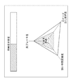
ここで、図3に表示部の表示画面を示す。
表示部3の表示画面には、レーダチャートによって急ブレーキ度、狭い車間距離度、スピード出し過ぎ度が表される。
また、現在のどの運転状態が同乗者快適ゾーンに入っているかをよりわかりやすく運転者に知らせるため、レーダチャート中に同乗者快適ゾーンが設定されている。
表示部3の表示画面には、上段に同乗者不快度を表す棒グラフが表示され、運転者は同乗者にどれくらい不快度が蓄積されているかを知ることができる。
なお、棒グラフ中において斜線部分が不快感を表し、斜線部分が右側に延びるにつれて不快感は増大する。
FIG. 3 shows a display screen of the display unit.
On the display screen of the
In addition, a passenger comfort zone is set in the radar chart in order to inform the driver in an easy-to-understand manner which current driving state is in the passenger comfort zone.
On the display screen of the
In the bar graph, the shaded portion represents discomfort, and the discomfort increases as the shaded portion extends to the right.
すべての処理が終了すると、ステップ100へ戻り上述の処理を繰り返す。
なお本実施例において、ステップ100〜ステップ106、108、110が本発明における運転状態検出手段を構成し、ステップ107、109、111、112が本発明における同乗者不快感検出手段を構成する。またステップ113およびステップ114が本発明における報知手段を構成する。
When all the processes are completed, the process returns to step 100 and the above processes are repeated.
In this embodiment, steps 100 to 106, 108 and 110 constitute the driving state detecting means in the present invention, and steps 107, 109, 111 and 112 constitute the passenger discomfort detecting means in the present invention. Step 113 and step 114 constitute notification means in the present invention.
本実施例は以上のように構成され、急ブレーキ度算出判定部9によって急ブレーキ度不快判定を、スピード出し過ぎ度算出判定部10によってスピード出し過ぎ度不快判定を、狭い車間距離度算出判定部11によって狭い車間距離度不快判定を行うことによって同乗者にとって不快な運転状態を検出し、該検出結果を運転者に報知することによって、同乗者の感じている不快感を運転者に直接伝えて、運転操作の修正を促すことができる。
また、「急ブレーキ」、「狭い車間距離」、「スピード出し過ぎ」の3つの運転状態を検出し、急ブレーキ度、狭い車間距離度、スピード出し過ぎ度として運転者に報知することによって、運転者は自身の運転操作のどの部分に対して同乗者が不快と感じているのかを容易に理解することができる。
The present embodiment is configured as described above. The sudden braking degree
In addition, it detects three driving states, “Sudden braking”, “Narrow inter-vehicle distance”, and “Overspeed”, and informs the driver of the sudden braking degree, narrow inter-vehicle distance degree, and overspeeding degree. The person can easily understand which part of his / her driving operation the passenger feels uncomfortable.
また、「急ブレーキ」、「狭い車間距離」、「スピード出しすぎ」の3つの項目に対して、同乗者快適ゾーンを設定して、現在の運転状態が同乗者快適ゾーンに入っているかどうかを運転者に報知することによって、運転者は自身の運転操作のどの部分に対してどの程度改善すれば同乗者が快適になるのかを容易に理解することができる。 In addition, a passenger comfort zone is set for each of the three items of "sudden braking", "narrow inter-vehicle distance", and "speed too much", and whether or not the current driving state is in the passenger comfort zone. By notifying the driver, the driver can easily understand how much the driver's driving operation is improved and how much the passenger is comfortable.
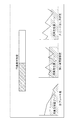
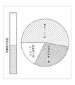
また上記実施例において、図3に示すようにレーダチャートを用いて急ブレーキ度、狭い車間距離度、スピード出し過ぎ度を運転者に提示するものとしたが、これに限定されず、たとえば図4に示すように折れ線グラフを用いたり、図5に示すように円グラフを用いたりすることもできる。
なお、円グラフを用いて提示を行う場合、急ブレーキ度、狭い車間距離度、スピード出し過ぎ度の各項目の相対的な面積の大小によって、どの項目について同乗者が不快感を感じているかを提示する。なお各項目の面積が同じ場合には、それぞれの項目について同乗者は同程度の不快感を感じていることを示す。
例示しないが、同乗者不快度についても、図3〜5に示す棒グラフ以外の表示方法を用いても良い。
これらの場合にも、上記のレーダチャートを用いて提示する場合と同じの効果を得ることができる。
In the above embodiment, as shown in FIG. 3, the radar chart is used to present the driver with the degree of sudden braking, the narrow distance between vehicles, and the degree of excessive speed, but the present invention is not limited to this. A line graph can be used as shown in FIG. 5, or a pie chart can be used as shown in FIG.
In addition, when presenting using a pie chart, it is indicated which item the passenger feels uncomfortable depending on the relative area of each item of sudden braking degree, narrow inter-vehicle distance degree, and overspeeding degree item. Present. In addition, when the area of each item is the same, it shows that the passenger feels the same degree of discomfort about each item.
Although not illustrated, display methods other than the bar graphs shown in FIGS. 3 to 5 may be used for passenger discomfort.
In these cases, the same effects as those obtained by using the radar chart can be obtained.
次に第2の実施例について説明する。
図6に、第2の実施例の全体構成を示す。
本実施例における気遣い運転ガイド装置は、第1の実施例における気遣い運転ガイド装置の表示部3および表示グラフ作成部13に代えて音楽再生部20および提示音楽選択部21を備えたものである。
車載コンピュータ4A内の提示音楽選択部21は、同乗者不快度算出部12で算出された同乗者の不快感を運転者に対して聴覚的に提示するための音楽を選択する。
音楽再生部20は、提示音楽選択部21で選択された音楽を再生する。
他の構成は、第1の実施例と同じであり、同一番号を付して説明を省略する。
Next, a second embodiment will be described.
FIG. 6 shows the overall configuration of the second embodiment.
The caring driving guide device in the present embodiment includes a
The presentation
The
Other configurations are the same as those of the first embodiment, and the same reference numerals are given and description thereof is omitted.
次に、気遣い運転ガイド処理について説明する。
図7は、気遣い運転ガイド処理の流れを示す図である。
ステップ200〜ステップ212は、第1の実施例の図2におけるステップ100〜112と同じであり説明を省略する。
ステップ213において提示音楽選択部21は、ステップ206において算出された急ブレーキ度、ステップ208において算出されたスピード出し過ぎ度およびステップ210において算出された狭い車間距離度、さらにステップ212で算出された同乗者不快度をもとに、図8に示す再生音楽選択表を参照して音楽を選択し、選択した音楽を音声信号として音楽再生部20へ出力する。
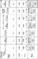
なお図8に示す再生音楽選択表は、横列に同乗者快適ゾーンを越えた項目、縦列に同乗者不快度の大きさをとる。
Next, the caring driving guide process will be described.
FIG. 7 is a diagram showing the flow of the caring driving guide process.
In
In the reproduction music selection table shown in FIG. 8, items exceeding the passenger comfort zone are shown in the horizontal rows, and the passenger discomfort level is shown in the vertical rows.
たとえば、同乗者不快度が中程度であり、同乗者快適ゾーンを越えた項目が狭い車間距離度である場合に、提示音楽選択部21は音楽Bを選択する。また同乗者不快度が極めて大きく、同乗者快適ゾーンを越えた項目が急ブレーキ度、狭い車間距離度、スピード出し過ぎ度すべての項目である場合には、「急ブレーキ・車間距離・スピードに気を付けてください」との音声メッセージを選択する。
なお図8に示す再生音楽選択表は、あらかじめ図示しない記憶部に記憶され提示音楽選択部21が参照可能となっている。
また、提示音楽選択部21が選択する音楽についても、それぞれの音データは図示しない記憶部にあらかじめ記憶されている。
音楽Aから音楽Gへ行くに従って、たとえばテンポの速い音楽を設定する。
For example, the presented
The reproduction music selection table shown in FIG. 8 is stored in advance in a storage unit (not shown) and can be referred to by the presentation
Also, for the music selected by the presented
As music A goes to music G, for example, fast-tempo music is set.
ステップ214において音楽再生部20は、提示音楽選択部21から入力された音声信号を再生して運転者に提示する。
すべての処理が終了すると、ステップ200へ戻り上述の処理を繰り返す。
なお本実施例において、ステップ200〜ステップ206、208、210が本発明における運転状態検出手段を構成し、ステップ207、209、211、212が本発明における同乗者不快感検出手段を構成する。またステップ213およびステップ214が本発明における報知手段を構成する。
In
When all the processes are completed, the process returns to step 200 and the above processes are repeated.
In this embodiment, steps 200 to 206, 208 and 210 constitute the driving state detecting means in the present invention, and steps 207, 209, 211 and 212 constitute the passenger discomfort detecting means in the present invention.
本実施例は以上のように構成され、同乗者快適ゾーンを越えた急ブレーキ度、狭い車間距離度、スピード出し過ぎ度と、同乗者不快度のレベルとの組合せに対応する音楽をあらかじめ図8に示す再生音楽選択表のように設定しておき、運転状態に応じて選択された音楽を音声提示することにより、運転者は自身の運転操作のどの部分に対して同乗者が不快と感じているのかを容易に理解することができ、運転操作の修正を促すことができる。 The present embodiment is configured as described above, and music corresponding to the combination of the degree of sudden braking beyond the passenger comfort zone, the narrow distance between vehicles, the excessive speed and the level of passenger discomfort is shown in FIG. As shown in the playback music selection table shown in Fig. 2, the driver feels uncomfortable with which part of his driving operation by presenting the music selected according to the driving state by voice. Can be easily understood and correction of driving operation can be promoted.
次に第3の実施例について説明する。
図9に、第3の実施例の全体構成を示す。
本実施例における気遣い運転ガイド装置は、第1の実施例における表示グラフ作成部13に代えて表示グラフ作成部13Bを備え、さらにジャーク算出部30と運転者不快度算出部31とを備えるものである。
車載コンピュータ4Bは、ジャーク算出部30と運転者不快度算出部31とを備える。
ジャーク算出部30は、車速検出部1によって検出された車速より減速度の時間変化を算出する。また運転者不快度算出部31は、ジャーク算出部30で算出されたジャークにもとづいて運転者の不快度を算出する。
表示グラフ作成部13Bは、運転者不快度算出部31および同乗者不快度算出部12によって算出された結果にもとづいて、表示部3に表示する表示映像を作成する。
他の構成は、第1の実施例と同じであり、同一番号を付して説明を省略する。
Next, a third embodiment will be described.
FIG. 9 shows the overall configuration of the third embodiment.
The caring driving guide device in this embodiment includes a display
The in-
The
The display
Other configurations are the same as those of the first embodiment, and the same reference numerals are given and description thereof is omitted.
次に、気遣い運転ガイド処理について説明する。
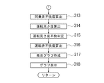
図10および図11は、気遣い運転ガイド処理の流れを示す図である。
ステップ300、ステップ301は、第1の実施例の図2におけるステップ100、ステップ101と同じであり説明を省略する。
ステップ302においてジャーク算出部30は、ステップ300で算出された車速をもとに、次の微分方程式を用いてジャークの算出を行う。
J=dA/dt=d2V/dt2 (5)
ここで、Jはジャーク、Aは減速度、Vは車速を表す。
ステップ303からステップ313は、第1の実施例の図2におけるステップ102からステップ112と同じであり説明を省略する。
Next, the caring driving guide process will be described.
FIG. 10 and FIG. 11 are diagrams showing the flow of the caring driving guide process.
Step 300 and step 301 are the same as
In
J = dA / dt = d 2 V / dt 2 (5)
Here, J represents jerk, A represents deceleration, and V represents vehicle speed.
次にステップ314において運転者不快度算出部31は、ステップ302で算出したジャークをもとに運転荒さ度を次式を用いて算出する。
DS=J (6)
ここで、DSは運転荒さ度、Jはジャークを表す。
なお本実施例においては、運転荒さ度=ジャークとする。
Next, in
DS = J (6)
Here, DS represents the degree of driving roughness, and J represents jerk.
In this embodiment, the degree of driving roughness is jerk.
ステップ315において運転者不快度算出部31は、算出した運転荒さ度にもとづいて、運転の荒さが運転者にとって不快であるかどうかの判定を行う。
ジャークは、通常の減速時にも0.5〜4.0[m/s3]程度の大きさで発生していることが知られている。従って、4.0[m/s3]以内の大きさのジャークが発生する状態は通常の動作状態であると考えらる。
In
It is known that jerk is generated at a size of about 0.5 to 4.0 [m / s 3 ] even during normal deceleration. Accordingly, it is considered that a state in which a jerk having a size within 4.0 [m / s 3 ] is generated is a normal operation state.
そこで本実施例では、運転者にとっての運転荒さ度の快適ゾーンを4.0[m/s3]以下とし、算出された運転荒さ度が4.0[m/s3]を超える場合、運転者不快度算出部31は運転者にとって不快な運転荒さ度であり、運転者は不快であると判定する。
ただし、運転荒さ度の最大値が7.0[m/s3]以上である場合、緊急度が高いため、運転者にとって安全性を優先して不快ではないと判定する。
ステップ316において運転者不快度算出部31は、急ブレーキ度が不快であると判定された時の運転荒さ度、狭い車間距離度が不快であると判定されたときの運転荒さ度、スピード出し過ぎ度が不快であると判定されたときの運転荒さ度をそれぞれ算出し、3つの平均値を運転者不快度として算出する。
Therefore, in this embodiment, when the comfortable zone of the driving roughness degree for the driver is set to 4.0 [m / s 3 ] or less and the calculated driving roughness degree exceeds 4.0 [m / s 3 ], driving is performed. The driver discomfort
However, when the maximum value of the degree of driving roughness is 7.0 [m / s 3 ] or more, since the degree of urgency is high, it is determined that the driver is not uncomfortable giving priority to safety.
In
ステップ317において表示グラフ作成部13Bは、テップ307において算出された急ブレーキ度、ステップ309において算出されたスピード出し過ぎ度およびステップ311において算出された狭い車間距離度、さらにステップ313で算出された同乗者不快度、ステップ316で算出された運転者不快度をもとに、運転者に視覚的に提示するための表示グラフの画像データを作成し、表示部3へ出力する。
ステップ318において表示部3は、表示グラフ作成部13Bから入力されたデータをもとに表示グラフを表示して運転者に提示する。
In
In
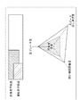
ここで、図12に表示部の表示画面を示す。
表示部3の表示画面には、レーダチャートによって急ブレーキ度、狭い車間距離度、スピード出し過ぎ度が表される。
さらに、表示部3の表示画面上段には、ステップ313で算出された同乗者不快度およびステップ316で算出された運転者不快度を表す棒グラフが表示される。
Here, FIG. 12 shows a display screen of the display unit.
On the display screen of the
Further, a bar graph representing the passenger discomfort level calculated in
すべての処理が終了すると、ステップ300へ戻り上述の処理を繰り返す。
なお本実施例において、ステップ300、301、303〜307、309、311が本発明における運転状態検出手段を構成し、ステップ308、310、312、313が本発明における同乗者不快感検出手段を構成する。またステップ317、318が本発明における報知手段を構成する。またステップ302、314、315が本発明における運転者不快感検出手段を構成する。
When all the processes are completed, the process returns to step 300 and the above processes are repeated.
In this embodiment, steps 300, 301, 303 to 307, 309, and 311 constitute the driving state detecting means in the present invention, and steps 308, 310, 312, and 313 constitute the passenger discomfort detecting means in the present invention. To do.
本実施例は以上のように構成され、運転者不快度と同乗者不快度の両方を、それぞれの相関関係がわかるように表示することによって、運転者の快適感と同乗者の快適感の差異が明確になり、運転者が自身の不快度と対応させながら同乗者のために気をつけるべき運転操作を明確に知ることができる。 The present embodiment is configured as described above, and by displaying both the driver discomfort level and the passenger discomfort level so that the respective correlations can be understood, the difference between the driver's comfort and the passenger's comfort is shown. It becomes clear, and it is possible to clearly know the driving operation that the driver should be careful for the passenger while dealing with his / her discomfort.
次に第4の実施例について説明する。
図13に、第4の実施例の全体構成を示す。
なお本実施例における気遣い運転ガイド装置は、第1の実施例における気遣い運転ガイド装置に同乗者検出部40と、車載コンピュータ内に優先度設定部41とを追加したものである。
同乗者検出部40は、たとえば着座用シートにとりつけられた圧力センサであり、助手席、後部座席のそれぞれに同乗者がいるかどうかを検出するものである。
同乗者検出部40からの同乗者有無情報は、車載コンピュータ4Cに入力される。
Next, a fourth embodiment will be described.
FIG. 13 shows the overall configuration of the fourth embodiment.
The caring driving guide device in the present embodiment is obtained by adding a
The
Passenger presence / absence information from the
車載コンピュータ4C内の優先度設定部41は、同乗者検出部40によって検出された同乗者の有無、急ブレーキ度算出判定部9によって算出された急ブレーキ度、スピード出し過ぎ度算出判定部10によって算出されたスピード出し過ぎ度、狭い車間距離度算出判定部11によって算出された狭い車間距離度にもとづいて、運転者に提示する気遣い運転ガイドの項目の優先度を設定する。
この気遣い運転ガイドの項目は、「車間距離が狭い」、「オーバースピード」、「急ブレーキ」とする。
The
The items of the caring driving guide are “the distance between the vehicles is narrow”, “overspeed”, and “sudden braking”.
表示グラフ作成部13Cは、優先度設定部41によって設定された優先度と、急ブレーキ度算出判定部9、スピード出し過ぎ度算出判定部10、狭い車間距離度算出判定部11において判定された不快判定とにもとづいて、同乗者不快度を運転者に対して視覚的に提示するためのグラフを生成するものである。
他の構成は、上記第1の実施例と同じであり同一番号を付して説明を省略する。
The display
Other configurations are the same as those of the first embodiment, and the same reference numerals are given and the description thereof is omitted.
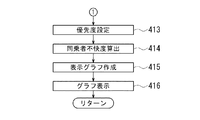
次に、気遣い運転ガイド処理について説明する。
図14、15は、気遣い運転ガイド処理の流れを示す図である。
ステップ400〜ステップ411は、第1の実施例の図2におけるステップ100〜ステップ111と同じであり説明を省略する。
ステップ412において同乗者検出部40は、同乗者の有無および着座位置を検出する。
なおステップ412における同乗者検出処理は、後述のステップ413の処理を行う前であればいつ行ってもよい。
Next, the caring driving guide process will be described.
14 and 15 are diagrams showing the flow of the caring driving guide process.
In
The passenger detection process in
ステップ413において優先度設定部41は、ステップ412で検出された同乗者の有無および着座位置の情報を用い、図16に示す優先度設定表にもとづき、運転者に提示する気遣い運転ガイドの項目の優先度を設定する。
助手席に同乗者がいる場合は、同乗者は車両の速度を体感できるため、オーバースピードである場合には同乗者は強い不快感を感じる。従って、提示の優先度を最も高くする。
また同乗者は自車両前方を視認して車間距離を確認することができるため、車間距離が狭い場合には同乗者は強い不快感を感じる。従って、提示の優先度を最も高くする。
同乗者は自車両前方を視認して車間距離を確認することができるため、急ブレーキ操作が行われることをあらかじめ予期することができる。従って、急ブレーキ操作が行われても、比較的不快感を感じないため、提示の優先度を低くする。
In
When there is a passenger in the passenger seat, the passenger can experience the speed of the vehicle, so that the passenger feels a strong discomfort when overspeeding. Therefore, the priority of presentation is made highest.
Further, since the passenger can visually check the front distance of the host vehicle and confirm the distance between the vehicles, the passenger feels a strong discomfort when the distance between the vehicles is small. Therefore, the priority of presentation is made highest.
Since the passenger can check the distance between the vehicles by visually checking the front of the host vehicle, it is possible to anticipate in advance that a sudden braking operation will be performed. Therefore, even if a sudden braking operation is performed, a relatively uncomfortable feeling is not felt, so the priority of presentation is lowered.
一方、後部座席に同乗者がいる場は、同乗者は車両の速度を体感できるため、オーバースピードである場合には同乗者は強い不快感を感じる。従って、提示の優先度を最も高くする。
また、同乗者は自車両前方を視認して車間距離を確認することができないため、車間距離が狭くても同乗者は比較的不快感を感じないため、提示の優先度を低くする。
同乗者は自車両前方を視認して車間距離を確認することができないため、急ブレーキ操作が行われた場合には同乗者にとって予期しないブレーキ操作となり、比較的不快感を感じることとなる。従って、提示の優先度を最も高くする。
さらに助手席と後部座席に同乗者がいる場合には、各提示項目において、助手席に同乗者がいる場合、後部座席に同乗者がいる場合のうち優先度が高い方の値を設定する。
なお図16中において、星マークの数が優先度の高さに比例する。
On the other hand, when there is a passenger in the rear seat, the passenger can feel the speed of the vehicle, so that the passenger feels a strong uncomfortable feeling at overspeed. Therefore, the priority of presentation is made highest.
In addition, since the passenger cannot visually confirm the front distance of the host vehicle and confirm the inter-vehicle distance, even if the inter-vehicle distance is small, the passenger does not feel a relatively uncomfortable feeling, so the priority of presentation is lowered.
Since the fellow passenger cannot visually confirm the front distance of the vehicle and confirm the distance between the vehicles, if the sudden braking operation is performed, the passenger will experience an unexpected braking operation and feel relatively uncomfortable. Therefore, the priority of presentation is made highest.
Further, when there are passengers in the passenger seat and the rear seat, the value of the higher priority is set in each presentation item when there is a passenger in the passenger seat or when there is a passenger in the rear seat.
In FIG. 16, the number of star marks is proportional to the priority level.
ステップ414において同乗者不快度算出部12は、ステップ407における急ブレーキ度不快判定、ステップ409におけるスピード出し過ぎ度不快判定およびステップ411における狭い車間距離度不快判定によって不快であると判定された回数の総和を求め、求めた結果を同乗者不快度として算出する。
ステップ415において表示グラフ作成部13Cは、ステップ413で設定された優先度にもとづいて、テップ406において算出された急ブレーキ度、ステップ408において算出されたスピード出し過ぎ度およびステップ410において算出された狭い車間距離度、さらにステップ414で算出された同乗者不快度をもとに、運転者に視覚的に提示するための表示グラフの画像データを作成し、表示部3へ出力する。
In
In
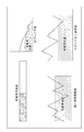
ここで、図17に表示部の表示画面を示す。
表示部3の表示画面には、レーダチャートによって急ブレーキ度、狭い車間距離度、スピード出し過ぎ度が表され、優先度の高い項目については大きく表示される。
ここでは助手席に同乗者がいるものとする。したがって、図16に示す優先度設定表にもとづいて「車間距離が狭い」および「オーバースピード」の項目が優先的に表示される、すなわち狭い車間距離度およびスピード出し過ぎ度の2つ項目が、大中小の表示サイズのうち大きなサイズで表示される。
Here, FIG. 17 shows a display screen of the display unit.
On the display screen of the
Here, it is assumed that there is a passenger in the passenger seat. Therefore, based on the priority setting table shown in FIG. 16, the items “near inter-vehicle distance” and “over-speed” are preferentially displayed, that is, two items, the narrow inter-vehicle distance degree and the excessive speed degree, It is displayed in a large size among large, medium and small display sizes.
このように、同乗者への気遣い運転ガイドとして「オーバースピード」の項目の優先度が高い場合にはスピード出し過ぎ度の表示を大きくすることにより、運転者に対して特にオーバースピードであることを認識させることができ、また「車間距離が狭い」の項目の優先度が高い場合には、狭い車間距離度の表示を大きくすることにより、運転者に対して特に車間距離が狭いことを認識させることができる。また「急ブレーキ」の項目の優先度が高い場合には、急ブレーキ度の表示を大きくすることにより、運転者に対して特に急ブレーキであることを認識させることができる。 In this way, when the priority of the `` overspeed '' item is high as a caring driver's guide for passengers, the overspeed indication is enlarged so that the driver is particularly overspeeded. When the priority of the item “Narrower inter-vehicle distance” is high, the driver can recognize that the inter-vehicle distance is particularly narrow by increasing the display of the narrow inter-vehicle distance degree. be able to. In addition, when the priority of the item of “sudden braking” is high, it is possible to make the driver recognize that the braking is particularly sudden by increasing the display of the sudden braking degree.
ステップ416において表示部3は、表示グラフ作成部13Cから入力された表示グラフを表示して運転者に提示する。
すべての処理が終了すると、ステップ400へ戻り上述の処理を繰り返す。
なお本実施例において、ステップ400〜ステップ406、408、410が本発明における運転状態検出手段を構成し、ステップ407、409、411、414が本発明における同乗者不快感検出手段を構成する。またステップ413、415、416が本発明における報知手段を構成する。またステップ412が本発明における同乗者検出手段を構成する。
In
When all the processes are completed, the process returns to step 400 and the above processes are repeated.
In this embodiment, steps 400 to 406, 408, 410 constitute the driving state detecting means in the present invention, and steps 407, 409, 411, 414 constitute the passenger discomfort detecting means in the present invention.
本実施例は以上のように構成され、同乗者検出部40によって同乗者が車両内のどの座席(助手席、後部座席等)にいるかを検出し、同乗者の検出位置に応じて気遣い運転ガイドの提示項目の優先度を変えることによって、同乗者の座っている座席の位置で変化する同乗者の不快感の違いに対応することができる。
また、同乗者が助手席にいる場合、後部座席にいる場合、助手席と後部座席の両方にいる場合の3つのパターンで、同乗者への気遣いガイドの優先度を変更することによって、同乗者の着座位置に応じてより細やかに、同乗者への気遣い運転ガイドを行うことができる。
The present embodiment is configured as described above, and the
In addition, by changing the priority of the caring guide for passengers in three patterns: when passengers are in the passenger seat, in the rear seat, and in both the passenger seat and the rear seat, It is possible to perform a caring driving guide for passengers more finely according to the seating position.
また、同乗者が助手席にいる場合、後部座席にいる場合、助手席と後部座席の両方にいる場合の3つの同乗者の着座パターンと、「急ブレーキ」、「狭い車間距離」、「スピード出しすぎ」の3つの運転状態とのすべての組合せ(計9通り)に応じて、気遣い運転ガイドの優先度を変更することによって、同乗者の座っている座席の位置と運転状態の組合せによって変化する同乗者の不快感の大きさに対応することができる。 In addition, when the passenger is in the passenger seat, in the rear seat, in the passenger seat and in the rear seat, the seating pattern of the three passengers, "Sudden braking", "Narrow inter-vehicle distance", "Speed By changing the priority of the caring driving guide according to all combinations (three ways in total) with the three driving states of “too much”, it changes depending on the combination of the position of the seat where the passenger is sitting and the driving state It is possible to deal with the magnitude of discomfort of passengers.
次に第5の実施例について説明する。
本実施例は、第4の実施例における急ブレーキ度算出判定部9の処理内容を変更したものであり、全体構成については説明を省略する。
急ブレーキ度算出判定部9は、減速度算出部5によって算出された減速度にもとづいて急ブレーキの原因を推定するものである。
Next, a fifth embodiment will be described.
In the present embodiment, the processing content of the sudden braking degree
The sudden braking degree
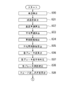
次に、気遣い運転ガイド処理について説明する。
図18、19は、気遣い運転ガイド処理の流れを示す図である。
ステップ500〜ステップ507は、第1の実施例の図2におけるステップ100〜ステップ107と同じであり説明を省略する。
ステップ508において急ブレーキ度算出判定部9は、急ブレーキの原因を推定する。急ブレーキ度の最大値が6.0[m/s2]以上である場合、緊急回避が原因であると推定する。急ブレーキ度の最大値が6.0[m/s2]未満で、かつ、最小値が1.0[m/s2]未満の場合は、減速度の変動が大きく、交差点信号のタイミングを見誤ったものと推定する。また、急ブレーキ度の最大値が6.0[m/s2]未満で、かつ、最小値が1.0[m/s2]以上の場合は、単にブレーキタイミングが遅かったものと推定する。
ステップ509からステップ512は第1の実施例におけるステップ108〜ステップ111と同じであり説明を省略する。
Next, the caring driving guide process will be described.
18 and 19 are diagrams showing the flow of the caring driving guide process.
In
ステップ513において同乗者検出部40は、同乗者の有無および着座位置を検出する。
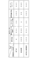
ステップ514において優先度設定部41は、ステップ513で検出された同乗者の有無および着座位置の情報、ステップ508における急ブレーキ原因判定結果を用いて、図20に示す優先度設定表にもとづき同乗者への気遣い運転ガイドの優先度を設定する。
助手席に同乗者がいる場合は、同乗者は自車両前方を視認して、緊急回避のための急ブレーキを予測することができる。従って緊急回避のための急ブレーキ操作が行われても比較的不快感を感じないため、提示の優先度を最も低くする。
また自車両前方を視認して信号が近づいていることを認識することができるので、信号タイミングを見誤ったことによる急ブレーキ操作が行われると同乗者は強い不快感を感じる。従って、提示の優先度を最も高くする。
同乗者は自車両前方を視認して、先行車両との距離を認識することができるので、ブレーキタイミングが遅いことによる急ブレーキ操作が行われると、同乗者は不快感を感じる。従って、提示の優先度を通常に設定する。
In
In
When a passenger is present in the passenger seat, the passenger can visually recognize the front of the vehicle and predict sudden braking for emergency avoidance. Therefore, even if a sudden braking operation for emergency avoidance is performed, a relatively uncomfortable feeling is not felt, and therefore the priority of presentation is made the lowest.
Further, since it is possible to recognize that the signal is approaching by visually recognizing the front of the host vehicle, the passenger feels a strong discomfort when a sudden braking operation is performed due to misreading the signal timing. Therefore, the priority of presentation is made highest.
Since the passenger can visually recognize the front of the host vehicle and recognize the distance from the preceding vehicle, the passenger feels uncomfortable when a sudden braking operation is performed due to the late brake timing. Therefore, the priority of presentation is set to normal.
一方後部座席に同乗者がいる場合には、同乗者は自車両前方を視認することができないため、緊急回避のためのブレーキ操作が行われると同乗者にとっては予期しないブレーキ操作となり、強い不快感を感じることとなる。従って、提示の優先度を最も高くする。
また、同乗者は交差点信号に近づいていることを認識することができないので、信号タイミングを見誤ったことによる急ブレーキ操作が行われると、同乗者にとっては予期しないブレーキ操作となり、強い不快感を感じることとなる。従って、提示の優先度を最も高くする。
ブレーキタイミングが遅いことによる急ブレーキ操作が行われた場合には、同乗者は比較的不快感を感じないため、提示の優先度を最も低くする。
さらに助手席と後部座席に同乗者がいる場合には、各提示項目において、助手席に同乗者がいる場合、後部座席に同乗者がいる場合のうち優先度が高いほうの値を設定する。
なお図20中において、星マークの数が優先度の高さに比例する。
On the other hand, if there is a passenger in the rear seat, the passenger cannot visually see the front of the vehicle, so if the brake operation for emergency avoidance is performed, the passenger will experience an unexpected brake operation and strong discomfort Will feel. Therefore, the priority of presentation is made highest.
In addition, since the passenger cannot recognize that he is approaching the intersection signal, if a sudden braking operation is performed due to misreading the signal timing, the passenger will experience an unexpected braking operation and a strong discomfort. You will feel it. Therefore, the priority of presentation is made highest.
When a sudden braking operation is performed due to the late brake timing, the passenger does not feel discomfort relatively, so the priority of presentation is set to the lowest.
Further, when there are passengers in the passenger seat and the rear seat, a value having a higher priority is set in each presentation item when there is a passenger in the passenger seat or when there is a passenger in the rear seat.
In FIG. 20, the number of star marks is proportional to the priority level.
ステップ515において同乗者不快度算出部12は、ステップ507における急ブレーキ度不快判定、ステップ510におけるスピード出し過ぎ度不快判定およびステップ512における狭い車間距離度不快判定によって不快であると判定された回数の総和を求め、求めた結果を同乗者不快度として算出する。
ステップ516において表示グラフ作成部13Cは、ステップ514で設定された優先度にもとづいて、テップ506において算出された急ブレーキ度、ステップ509において算出されたスピード出し過ぎ度およびステップ511において算出された狭い車間距離度、さらにステップ515で算出された同乗者不快度をもとに、運転者に視覚的に提示するための表示グラフの画像データを作成し、表示部3へ出力する。
ステップ517において表示部3は、表示グラフ作成部13Cから入力されたデータをもとに表示グラフを表示して運転者に提示する。
In
In
In
ここで、図21に表示部の表示画面を示す。
表示部3の表示画面には、運転者に提示する急ブレーキ度、スピード出し過ぎ度、狭い車間距離度の3つの項目について、優先度の高い項目については大きな表示によって提示する。
ここでは急ブレーキの原因が信号見誤りであり、さらに助手席に同乗者がいるものとする。したがって、図20に示す優先度設定表にもとづいて、「急ブレーキ」、「車間距離が狭い」および「オーバースピード」の3項目を優先的に表示する、すなわち急ブレーキ、狭い車間距離度およびスピード出し過ぎ度の3つの項目を、大中小の表示サイズのうち大きなサイズで表示する。
FIG. 21 shows a display screen of the display unit.
On the display screen of the
Here, it is assumed that the cause of sudden braking is a signal misreading, and there is a passenger in the passenger seat. Therefore, based on the priority setting table shown in FIG. 20, three items of “sudden braking”, “near inter-vehicle distance” and “overspeed” are preferentially displayed, that is, sudden braking, narrow inter-vehicle distance degree and speed. Three items of the degree of overloading are displayed in a large size among large, medium and small display sizes.
すべての処理が終了すると、ステップ500へ戻り上述の処理を繰り返す。
なお本実施例において、ステップ500〜ステップ506、508、509、511が本発明における運転状態検出手段を構成し、ステップ507、510、512、515が本発明における同乗者不快感検出手段を構成する。またステップ514、516、517が本発明における報知手段を構成する。ステップ513が本発明における同乗者検出手段を構成する。
When all the processes are completed, the process returns to step 500 and the above processes are repeated.
In this embodiment, steps 500 to 506, 508, 509, and 511 constitute the driving state detecting means in the present invention, and steps 507, 510, 512, and 515 constitute the passenger discomfort detecting means in the present invention. .
本実施例は以上のように構成され、急ブレーキをかけた運転状態において、緊急回避のために急ブレーキをかけた場合と、信号タイミングを見誤って急ブレーキをかけた場合と、ブレーキのかけ始めのタイミングが遅れたために急ブレーキをかけた場合とで、気遣い運転ガイドの提示項目の優先度を変更することによって、同乗者の座っている座席の位置と「急ブレーキ」の運転状態に陥った原因の組合せによって変化する同乗者の不快感の大きさに対応することができる。 The present embodiment is configured as described above. In the driving state in which the brake is suddenly applied, the case where the brake is suddenly applied for emergency avoidance, the case where the signal brake is mistakenly applied and the brake is applied suddenly, and the brake is applied. By changing the priority of the items presented in the caring driving guide when the start timing is late and sudden braking is applied, the passenger sits in the position of the seat where the passenger is sitting and the driving state of `` sudden braking '' It is possible to deal with the magnitude of passenger discomfort that varies depending on the combination of causes.
1 車速検出部
2 車間距離検出部
3 表示部
4、4A、4B、4C 車載コンピュータ
5 減速度算出部
6 最高車速算出部
7 平均車速算出部
8 平均車間距離算出部
9 急ブレーキ度算出判定部
10 スピード出し過ぎ度算出判定部
11 狭い車間距離度算出判定部
12 同乗者不快度算出部
13、13B、13C 表示グラフ作成部
20 音楽再生部
21 提示音楽選択部
30 ジャーク算出部
31 運転者不快度算出部
40 同乗者検出部
41 優先度設定部
DESCRIPTION OF
Claims (13)
該運転状態検出手段によって検出された運転状態にもとづいて、同乗者にとって不快な運転状態であるかどうかを検出する同乗者不快感検出手段と、
該同乗者不快感検出手段の検出結果を運転者に報知する報知手段とを有することを特徴とする気遣い運転ガイド装置。 Driving state detecting means for detecting the driving state;
Passenger discomfort detection means for detecting whether the driving state is uncomfortable for the passenger based on the driving state detected by the driving state detection means;
A caring driving guide device comprising: an informing means for informing a driver of a detection result of the passenger discomfort detecting means.
前記報知手段は、前記同乗者検出手段によって検出された同乗者の着座位置に応じて、前記運転者に報知する運転状態の表示態様を変更することを特徴とする請求項2に記載の気遣い運転ガイド装置。 Passenger detection means for determining the sitting position of the passenger,
The caring driving according to claim 2, wherein the notifying unit changes a display state of a driving state to be informed to the driver according to a seating position of the passenger detected by the passenger detecting unit. Guide device.
前記同乗者検出手段によって検出された同乗者の着座位置に応じて、前記運転者に報知する運転状態の項目の優先度を決定し、該優先度にもとづいて、前記運転者に報知する運転状態の項目ごとに表示態様を変更することであることを特徴とする請求項3に記載の気遣い運転ガイド装置。 The change of the display state of the driving state performed by the notification means is as follows:
In accordance with the passenger's sitting position detected by the passenger detection means, the priority of the item of the driving state to be notified to the driver is determined, and the driving state to be notified to the driver based on the priority The caring driving guide device according to claim 3, wherein the display mode is changed for each item.
前記報知手段が報知する運転状態の項目は、前記運転状態検出手段によって検出された運転状態の項目と対応することを特徴とする請求項2から4のいずれか1に記載の気遣い運転ガイド装置。 The driving state detected by the driving state detecting means is at least one of three items of sudden braking, narrow inter-vehicle distance, and excessive speed,
The caring driving guide device according to any one of claims 2 to 4, wherein the item of the driving state notified by the notifying unit corresponds to the item of the driving state detected by the driving state detecting unit.
前記報知手段は、急ブレーキの原因にもとづいて、前記運転者に報知する運転状態のブレーキの項目における優先度を決定し、該優先度にもとづいて、前記運転者に報知する運転状態のブレーキの項目の表示態様を変更することを特徴とする請求項5または6に記載の気遣い運転ガイド装置。 When the driving state detecting means detects that the driving state is uncomfortable for the passenger for the item of sudden braking, it further detects the cause of sudden braking,
The notification means determines a priority in the item of the brake of the driving state to be notified to the driver based on the cause of the sudden braking, and the brake of the driving state to be notified to the driver based on the priority is determined. The caring driving guide device according to claim 5 or 6, wherein a display mode of the item is changed.
前記報知手段は、さらに前記運転者不快感検出手段の検出結果を前記同乗者不快感検出手段の検出結果との相関関係がわかるように、運転者に報知することを特徴とする請求項1から11のいずれか1に記載の気遣い運転ガイド装置。 Based on the driving state detected by the driving state detection means, comprising a driver discomfort detection means for detecting whether the driving state is uncomfortable for the driver,
The notification means further notifies the driver so that a correlation between a detection result of the driver discomfort detection means and a detection result of the passenger discomfort detection means can be understood. The caring driving guide device according to any one of 11.
Priority Applications (1)
| Application Number | Priority Date | Filing Date | Title |
|---|---|---|---|
| JP2004349507A JP4543905B2 (en) | 2004-12-02 | 2004-12-02 | Caring driving guide device and caring driving guide method |
Applications Claiming Priority (1)
| Application Number | Priority Date | Filing Date | Title |
|---|---|---|---|
| JP2004349507A JP4543905B2 (en) | 2004-12-02 | 2004-12-02 | Caring driving guide device and caring driving guide method |
Publications (2)
| Publication Number | Publication Date |
|---|---|
| JP2006163473A true JP2006163473A (en) | 2006-06-22 |
| JP4543905B2 JP4543905B2 (en) | 2010-09-15 |
Family
ID=36665460
Family Applications (1)
| Application Number | Title | Priority Date | Filing Date |
|---|---|---|---|
| JP2004349507A Expired - Fee Related JP4543905B2 (en) | 2004-12-02 | 2004-12-02 | Caring driving guide device and caring driving guide method |
Country Status (1)
| Country | Link |
|---|---|
| JP (1) | JP4543905B2 (en) |
Cited By (6)
| Publication number | Priority date | Publication date | Assignee | Title |
|---|---|---|---|---|
| JP2009145828A (en) * | 2007-12-18 | 2009-07-02 | Fujitsu Ten Ltd | Eco driving support device |
| JP2012106714A (en) * | 2010-10-18 | 2012-06-07 | Mazda Motor Corp | Display device for vehicle |
| JP2013069020A (en) * | 2011-09-21 | 2013-04-18 | Nissan Motor Co Ltd | Eco-driving support device |
| JP2019098779A (en) * | 2017-11-28 | 2019-06-24 | 株式会社Subaru | Driving advice device and driving advice method |
| WO2019203107A1 (en) * | 2018-04-18 | 2019-10-24 | 株式会社Jvcケンウッド | Drive recorder, display control method, and program |
| US12434729B2 (en) * | 2022-07-25 | 2025-10-07 | Toyota Jidosha Kabushiki Kaisha | Driver assistance system for vehicle including display having different implementation options |
Citations (6)
| Publication number | Priority date | Publication date | Assignee | Title |
|---|---|---|---|---|
| JPH06278574A (en) * | 1993-03-26 | 1994-10-04 | Mazda Motor Corp | Vehicle seat belt wearing promotion device |
| JPH10264681A (en) * | 1997-03-25 | 1998-10-06 | Nissan Motor Co Ltd | Vehicle control device |
| JPH1164009A (en) * | 1997-08-27 | 1999-03-05 | Toyota Motor Corp | Vehicle environmental condition output device, method, and medium |
| JP2000268297A (en) * | 1999-03-16 | 2000-09-29 | Nissan Motor Co Ltd | Safe driving evaluation device |
| JP2001004382A (en) * | 1999-06-23 | 2001-01-12 | Matsushita Electric Ind Co Ltd | In-vehicle navigation device and road information communication system |
| JP2004289523A (en) * | 2003-03-24 | 2004-10-14 | Aisin Seiki Co Ltd | Vehicle operation status display device |
-
2004
- 2004-12-02 JP JP2004349507A patent/JP4543905B2/en not_active Expired - Fee Related
Patent Citations (6)
| Publication number | Priority date | Publication date | Assignee | Title |
|---|---|---|---|---|
| JPH06278574A (en) * | 1993-03-26 | 1994-10-04 | Mazda Motor Corp | Vehicle seat belt wearing promotion device |
| JPH10264681A (en) * | 1997-03-25 | 1998-10-06 | Nissan Motor Co Ltd | Vehicle control device |
| JPH1164009A (en) * | 1997-08-27 | 1999-03-05 | Toyota Motor Corp | Vehicle environmental condition output device, method, and medium |
| JP2000268297A (en) * | 1999-03-16 | 2000-09-29 | Nissan Motor Co Ltd | Safe driving evaluation device |
| JP2001004382A (en) * | 1999-06-23 | 2001-01-12 | Matsushita Electric Ind Co Ltd | In-vehicle navigation device and road information communication system |
| JP2004289523A (en) * | 2003-03-24 | 2004-10-14 | Aisin Seiki Co Ltd | Vehicle operation status display device |
Cited By (8)
| Publication number | Priority date | Publication date | Assignee | Title |
|---|---|---|---|---|
| JP2009145828A (en) * | 2007-12-18 | 2009-07-02 | Fujitsu Ten Ltd | Eco driving support device |
| JP2012106714A (en) * | 2010-10-18 | 2012-06-07 | Mazda Motor Corp | Display device for vehicle |
| JP2013069020A (en) * | 2011-09-21 | 2013-04-18 | Nissan Motor Co Ltd | Eco-driving support device |
| JP2019098779A (en) * | 2017-11-28 | 2019-06-24 | 株式会社Subaru | Driving advice device and driving advice method |
| US10647326B2 (en) | 2017-11-28 | 2020-05-12 | Subaru Corporation | Driving advice apparatus and driving advice method |
| WO2019203107A1 (en) * | 2018-04-18 | 2019-10-24 | 株式会社Jvcケンウッド | Drive recorder, display control method, and program |
| JP2019191639A (en) * | 2018-04-18 | 2019-10-31 | 株式会社Jvcケンウッド | Drive recorder, display control method, and program |
| US12434729B2 (en) * | 2022-07-25 | 2025-10-07 | Toyota Jidosha Kabushiki Kaisha | Driver assistance system for vehicle including display having different implementation options |
Also Published As
| Publication number | Publication date |
|---|---|
| JP4543905B2 (en) | 2010-09-15 |
Similar Documents
| Publication | Publication Date | Title |
|---|---|---|
| JP6323549B2 (en) | Vehicle information presentation device | |
| US9475502B2 (en) | Coordinated vehicle response system and method for driver behavior | |
| EP1891490B1 (en) | Dialogue system | |
| JP6203421B2 (en) | Driver support device and alarm timing control method | |
| JPH10288532A (en) | Voice guidance device for vehicles | |
| US10752172B2 (en) | System and method to control a vehicle interface for human perception optimization | |
| JP6331945B2 (en) | Psychological state estimation device and psychological state estimation method | |
| JP4543905B2 (en) | Caring driving guide device and caring driving guide method | |
| US12263856B2 (en) | Notification system, notification method, and non-transitory storage medium | |
| JP4051813B2 (en) | Information device | |
| JP2006232174A (en) | Vehicle driving support device | |
| JP6946728B2 (en) | Vehicle operation control system and vehicle operation control method | |
| JP5803679B2 (en) | Operating state determination device | |
| CN113879319B (en) | Drowsiness sign notification system | |
| JP2022133105A (en) | Information presentation method and information presentation device | |
| US20250001933A1 (en) | Display control device and display control method | |
| JP2005128631A (en) | Driving assistance device | |
| JP2006232033A (en) | Driving tendency estimation device and driving tendency estimation method | |
| JP2006308507A (en) | Caring driving guide device and caring driving guide method | |
| JP2009029204A (en) | Operating status notification device | |
| JP5357796B2 (en) | Operation behavior guidance system | |
| JP2006182325A (en) | Vehicle alarm device | |
| JPWO2008038375A1 (en) | Information processing apparatus, information processing method, information processing program, and computer-readable recording medium | |
| JP2005335648A (en) | Information presentation apparatus and method | |
| US12434728B2 (en) | Vehicle operator drowsiness alert |
Legal Events
| Date | Code | Title | Description |
|---|---|---|---|
| A621 | Written request for application examination |
Free format text: JAPANESE INTERMEDIATE CODE: A621 Effective date: 20071029 |
|
| RD04 | Notification of resignation of power of attorney |
Free format text: JAPANESE INTERMEDIATE CODE: A7424 Effective date: 20080912 |
|
| A977 | Report on retrieval |
Free format text: JAPANESE INTERMEDIATE CODE: A971007 Effective date: 20091029 |
|
| A131 | Notification of reasons for refusal |
Free format text: JAPANESE INTERMEDIATE CODE: A131 Effective date: 20100126 |
|
| A521 | Written amendment |
Free format text: JAPANESE INTERMEDIATE CODE: A523 Effective date: 20100217 |
|
| RD02 | Notification of acceptance of power of attorney |
Free format text: JAPANESE INTERMEDIATE CODE: A7422 Effective date: 20100217 |
|
| TRDD | Decision of grant or rejection written | ||
| A01 | Written decision to grant a patent or to grant a registration (utility model) |
Free format text: JAPANESE INTERMEDIATE CODE: A01 Effective date: 20100608 |
|
| A01 | Written decision to grant a patent or to grant a registration (utility model) |
Free format text: JAPANESE INTERMEDIATE CODE: A01 |
|
| A61 | First payment of annual fees (during grant procedure) |
Free format text: JAPANESE INTERMEDIATE CODE: A61 Effective date: 20100621 |
|
| FPAY | Renewal fee payment (event date is renewal date of database) |
Free format text: PAYMENT UNTIL: 20130709 Year of fee payment: 3 |
|
| R150 | Certificate of patent or registration of utility model |
Free format text: JAPANESE INTERMEDIATE CODE: R150 |
|
| LAPS | Cancellation because of no payment of annual fees |