JP2006187807A - Automatic determination of plasma torch operation mode - Google Patents
Automatic determination of plasma torch operation mode Download PDFInfo
- Publication number
- JP2006187807A JP2006187807A JP2005379182A JP2005379182A JP2006187807A JP 2006187807 A JP2006187807 A JP 2006187807A JP 2005379182 A JP2005379182 A JP 2005379182A JP 2005379182 A JP2005379182 A JP 2005379182A JP 2006187807 A JP2006187807 A JP 2006187807A
- Authority
- JP
- Japan
- Prior art keywords
- cutting
- arc
- plasma
- torch
- mode
- Prior art date
- Legal status (The legal status is an assumption and is not a legal conclusion. Google has not performed a legal analysis and makes no representation as to the accuracy of the status listed.)
- Pending
Links
- 238000005520 cutting process Methods 0.000 claims description 147
- 230000008859 change Effects 0.000 claims description 5
- 238000000926 separation method Methods 0.000 claims description 5
- 230000001960 triggered effect Effects 0.000 claims description 4
- 238000010891 electric arc Methods 0.000 claims description 3
- 229910052751 metal Inorganic materials 0.000 description 42
- 239000002184 metal Substances 0.000 description 42
- 239000007787 solid Substances 0.000 description 11
- 238000000034 method Methods 0.000 description 10
- 230000005540 biological transmission Effects 0.000 description 6
- 230000008033 biological extinction Effects 0.000 description 4
- 238000003754 machining Methods 0.000 description 4
- 239000000463 material Substances 0.000 description 4
- 230000008569 process Effects 0.000 description 4
- XEEYBQQBJWHFJM-UHFFFAOYSA-N Iron Chemical compound [Fe] XEEYBQQBJWHFJM-UHFFFAOYSA-N 0.000 description 2
- 230000002411 adverse Effects 0.000 description 2
- 230000015556 catabolic process Effects 0.000 description 2
- 238000001816 cooling Methods 0.000 description 2
- 238000006731 degradation reaction Methods 0.000 description 2
- 238000012544 monitoring process Methods 0.000 description 2
- 230000004044 response Effects 0.000 description 2
- 230000007704 transition Effects 0.000 description 2
- 238000005493 welding type Methods 0.000 description 2
- QCWXUUIWCKQGHC-UHFFFAOYSA-N Zirconium Chemical compound [Zr] QCWXUUIWCKQGHC-UHFFFAOYSA-N 0.000 description 1
- 238000006243 chemical reaction Methods 0.000 description 1
- 238000010276 construction Methods 0.000 description 1
- 238000001514 detection method Methods 0.000 description 1
- 230000001627 detrimental effect Effects 0.000 description 1
- 230000000694 effects Effects 0.000 description 1
- 229910052735 hafnium Inorganic materials 0.000 description 1
- VBJZVLUMGGDVMO-UHFFFAOYSA-N hafnium atom Chemical compound [Hf] VBJZVLUMGGDVMO-UHFFFAOYSA-N 0.000 description 1
- 230000000977 initiatory effect Effects 0.000 description 1
- 229910052742 iron Inorganic materials 0.000 description 1
- 238000012423 maintenance Methods 0.000 description 1
- 239000007769 metal material Substances 0.000 description 1
- 239000011343 solid material Substances 0.000 description 1
- 239000010421 standard material Substances 0.000 description 1
- 239000007858 starting material Substances 0.000 description 1
- 239000000126 substance Substances 0.000 description 1
- 229910052726 zirconium Inorganic materials 0.000 description 1
Images
Classifications
-
- B—PERFORMING OPERATIONS; TRANSPORTING
- B23—MACHINE TOOLS; METAL-WORKING NOT OTHERWISE PROVIDED FOR
- B23K—SOLDERING OR UNSOLDERING; WELDING; CLADDING OR PLATING BY SOLDERING OR WELDING; CUTTING BY APPLYING HEAT LOCALLY, e.g. FLAME CUTTING; WORKING BY LASER BEAM
- B23K10/00—Welding or cutting by means of a plasma
-
- B—PERFORMING OPERATIONS; TRANSPORTING
- B23—MACHINE TOOLS; METAL-WORKING NOT OTHERWISE PROVIDED FOR
- B23K—SOLDERING OR UNSOLDERING; WELDING; CLADDING OR PLATING BY SOLDERING OR WELDING; CUTTING BY APPLYING HEAT LOCALLY, e.g. FLAME CUTTING; WORKING BY LASER BEAM
- B23K10/00—Welding or cutting by means of a plasma
- B23K10/006—Control circuits therefor
-
- H—ELECTRICITY
- H05—ELECTRIC TECHNIQUES NOT OTHERWISE PROVIDED FOR
- H05H—PLASMA TECHNIQUE; PRODUCTION OF ACCELERATED ELECTRICALLY-CHARGED PARTICLES OR OF NEUTRONS; PRODUCTION OR ACCELERATION OF NEUTRAL MOLECULAR OR ATOMIC BEAMS
- H05H1/00—Generating plasma; Handling plasma
- H05H1/24—Generating plasma
- H05H1/26—Plasma torches
- H05H1/32—Plasma torches using an arc
- H05H1/34—Details, e.g. electrodes, nozzles
- H05H1/36—Circuit arrangements
Landscapes
- Engineering & Computer Science (AREA)
- Physics & Mathematics (AREA)
- Plasma & Fusion (AREA)
- Mechanical Engineering (AREA)
- Spectroscopy & Molecular Physics (AREA)
- Arc Welding In General (AREA)
- Plasma Technology (AREA)
- Arc Welding Control (AREA)
Abstract
Description
本発明は、プラズマ切断装置に関し、詳細には、このような装置を用いて使用するためのコントローラに関する。 The present invention relates to a plasma cutting device, and in particular to a controller for use with such a device.
プラズマ切断は、被加工材を切断するために電気アーク(電弧)を使用する加工である。プラズマ切断装置は、典型的には、電力源、エア供給器、トーチを含む。トーチまたはプラズマトーチは、切断を実行するプラズマアークを創成し維持するために使用される。プラズマ切断電力源は、送電ソケットから入力ボルトを受取り、一対の電力端子へ電力を供給する。一対の電力端子の一方は電極へ接続され、他方は被加工材へ接続される。エア供給器は、被加工材へアークを搬送し、トーチを冷却するために、大部分のプラズマ切断装置で使用される。 Plasma cutting is a process that uses an electric arc to cut a workpiece. A plasma cutting device typically includes a power source, an air supply, and a torch. A torch or plasma torch is used to create and maintain a plasma arc that performs the cutting. The plasma cutting power source receives an input bolt from the power transmission socket and supplies power to the pair of power terminals. One of the pair of power terminals is connected to the electrode, and the other is connected to the workpiece. Air feeders are used in most plasma cutting devices to carry the arc to the workpiece and cool the torch.
この切断加工を開始する方法は多数ある。例えば、接点スタート、高周波または高電圧スタートである。一般的に、接点スタートプラズマ切断装置において、可動もしくは固定の電極または消耗材は、カソード(マイナス極)の役割を持ち、可動もしくは固定のノズルまたはチップは、アノード(プラス極)の役割を持つ。いくつかの装置では、エア供給器が、初期アークまたはパイロット(先立ち)アークを創成することを目的として電極とチップの分離を実行するために使用される。その他の装置では、機械的手段または電気機械的手段が、接点を分離してパイロット・アークを発生させる役割を持つ。各ケースにおいて、一度パイロット・アークが確立されると、エアがパイロット・アークを通過させられる。パイロット・アークにより、エアは加熱されてイオン化されプラズマジェットを形成する。プラズマジェットは、ノズルの開口を通過してトーチの外へ出される。エアは、被加工材へアークを伸ばすことを助け、切断アークを形成し切断加工を開始する。 There are many ways to start this cutting process. For example, contact start, high frequency or high voltage start. In general, in a contact start plasma cutting apparatus, a movable or fixed electrode or a consumable material has a role of a cathode (negative pole), and a movable or fixed nozzle or tip has a role of an anode (positive pole). In some devices, an air supply is used to perform electrode and tip separation for the purpose of creating an initial arc or pilot (pre-) arc. In other devices, mechanical or electromechanical means are responsible for separating the contacts and generating a pilot arc. In each case, air is passed through the pilot arc once the pilot arc is established. With the pilot arc, the air is heated and ionized to form a plasma jet. The plasma jet passes through the nozzle opening and exits the torch. The air helps to extend the arc to the workpiece, forms a cutting arc and starts the cutting process.
他の装置は、高周波スタータを利用して、パイロット・アークと切断アークを開始する。さらに他の装置は、高電圧を採用して、パイロット・アークと切断アークを開始する。いずれの組立体においても、カソード部材とアノード部材の隙間関係や移動範囲は、パイロット・アークを発生させたり切断アークを保持したりするために、精密なデザインやメンテナンスを必要とする。 Other devices utilize high frequency starters to initiate pilot and cutting arcs. Still other devices employ high voltage to initiate pilot and cutting arcs. In any assembly, the gap relationship and the movement range between the cathode member and the anode member require precise design and maintenance in order to generate a pilot arc and hold a cutting arc.
上記装置は、パイロット・アークを発生させるために使用されるが、いくつかの装置は、複数の作動モードを提供する。このモードの一つは、エキスパンデッドメタル(壁下地用の金網)切断モードである。エキスパンデッドメタル・モード(EMM)は、オペレータが、多数の個別プラズマ切断を一つの引き金作動により実行するのを可能とする。このモードは、オペレータが「破断メタル」を迅速かつ効率的に切断するのを可能にする。「破断メタル」とは、鉄格子、メッシュ、スクリーン、チェーン、チェーンリンク・フェンスその他の空隙により分離された金属材料を言う。エキスパンデッドメタル切断モード中は、プラズマトーチは、被加工材内の空隙の存在の下でアークを保持するよう試みる。これを果たすため、コントローラが、被加工材の空隙に基づき切断アークがしぼもうとすることを予測する時、パイロット・アーク回路は、切断アークがしぼむ時にパイロット・アークが形成されることを可能にする。パイロット・アークは、アークを被加工材の空隙中で維持されるように、プラズマトーチ内で保持される。被加工材の空隙(裂け目)が一度通過されると、切断アークは被加工材を切断するために再構築される。この加工は、エキスパンデッドメタル切断操作が完了し引き金が外されるまで繰り返される。 Although the device is used to generate a pilot arc, some devices provide multiple modes of operation. One of the modes is an expanded metal cutting mode. Expanded metal mode (EMM) allows an operator to perform multiple individual plasma cuts with a single trigger operation. This mode allows the operator to cut “breaking metal” quickly and efficiently. "Broken metal" refers to metal materials separated by iron grids, meshes, screens, chains, chain links / fences and other voids. During the expanded metal cutting mode, the plasma torch attempts to hold the arc in the presence of voids in the workpiece. To accomplish this, when the controller predicts that the cutting arc will squeeze based on the workpiece gap, the pilot arc circuit allows the pilot arc to form when the cutting arc squeezes. To do. The pilot arc is held in a plasma torch so that the arc is maintained in the workpiece gap. Once the workpiece gap (crack) is passed, the cutting arc is reconstructed to cut the workpiece. This process is repeated until the expanded metal cutting operation is completed and the trigger is released.
エキスパンデッドメタル切断モードは、オペレータがエキスパンデッドメタルを効率的に切断可能にする一方、このモードは、プラズマトーチの消耗材により経験される磨耗を増加させる。この磨耗は、エキスパンデッドメタル切断モードにおいては正常であるが、オペレータが普通のソリッドメタル(中実の金属)切断を実施しようとする時、プラズマトーチの作動により、プラズマトーチの部材が不要な磨耗にさらされる。すなわち、ソリッドメタルモードにおいて、プラズマトーチは、トーチ引き金作動状態でパイロット・アークを発生させることのみを必要とする。この加工の終了時、アークは完全にしぼんでしまう。それゆえ、エキスパンデッドメタルモードでソリッドメタルモード切断を実施することにより、過剰なパイロット・アーク発生が起きる。 While the expanded metal cutting mode allows the operator to cut the expanded metal efficiently, this mode increases the wear experienced by the consumable material of the plasma torch. This wear is normal in the expanded metal cutting mode, but when the operator tries to perform a normal solid metal cutting, the plasma torch is not required due to the operation of the plasma torch. Exposed to wear. That is, in the solid metal mode, the plasma torch only needs to generate a pilot arc in the torch trigger operating state. At the end of this process, the arc is completely deflated. Therefore, excessive pilot arcing occurs by performing solid metal mode cutting in expanded metal mode.
エキスパンデッドメタル切断は、切断加工の終了時に、利用可能な切断電力をいくぶん低減させることが可能となる。これは、切断アークがしぼむ間際を予測するための出力電流誤差検知に基づく装置または出力電流の変化の監視に基づく装置に関して特に正しい。特に、これらの予測装置により確認される「誤差」は、切断の終了時に大きくなるので、切断のクリーンな終了を確実にするために、電力はフルに利用しなくて良い。 Expanded metal cutting can reduce the available cutting power somewhat at the end of the cutting process. This is especially true for devices based on output current error detection or predicting changes in output current to predict when the cutting arc will collapse. In particular, since the “error” confirmed by these prediction devices becomes large at the end of cutting, it is not necessary to make full use of power to ensure a clean end of cutting.
それにもかかわらず、不要な磨耗や不正確な切断を引き起こすにもかかわらず、何人かのオペレータは、ソリッドメタルを切断する時にエキスパンデッドメタルモードで作動させるかもしれない。この問題を解決する試みの一つは、電力供給器上に手動スイッチを備えることである。この手動スイッチにより、オペレータは、プラズマ切断装置をあるモードから別のモードへ機械的に切り換える。しかし、多様な作業環境において、オペレータは、いくつかの異なった材料を一般的な連続方式で切断することを要求されるかもしれない。このような作業では、オペレータがプラズマトーチの作動モードを繰り返し変更することが必要となろう。このような要求は、オペレータが、繰り返し、特定の切断加工を中止し、電力源へ移動し切断モードを変更し、切断加工へ戻ることが必要となるため、加工効率に悪影響を与えるだけではなく、オペレータが制御の切り替えを忘れないことを保証するものでも無く、それを無視してエキスパンデッドメタルモードでソリッドメタルを切断することを続行するかもしれないのである。 Nevertheless, despite causing unnecessary wear and inaccurate cutting, some operators may operate in expanded metal mode when cutting solid metal. One attempt to solve this problem is to provide a manual switch on the power supply. With this manual switch, the operator mechanically switches the plasma cutting device from one mode to another. However, in a variety of work environments, an operator may be required to cut several different materials in a typical continuous manner. Such an operation would require the operator to repeatedly change the operating mode of the plasma torch. Such a request not only adversely affects machining efficiency, but also requires the operator to repeatedly stop a specific cutting process, move to a power source, change the cutting mode, and return to the cutting process. It does not guarantee that the operator will forget to switch control, and may ignore it and continue cutting solid metal in expanded metal mode.
それゆえ、各種モード間でプラズマトーチ切断装置を自動制御するプラズマ切断装置を設計することが求められることとなる。 Therefore, it is required to design a plasma cutting device that automatically controls the plasma torch cutting device between various modes.
本発明は、前述した欠点に打ち勝つ装置と方法を提供する。特に、コントローラは、プラズマトーチの切断モードを自動設定するように構成されている。コントローラは、装置の稼動をエキスパンデッドメタルモードで維持すべきか、または非エキスパンデッド(ソリッド)メタルモードで維持すべきかを、部分的には、切断アークの時間に基づいて決定する。 The present invention provides an apparatus and method that overcomes the aforementioned shortcomings. In particular, the controller is configured to automatically set the cutting mode of the plasma torch. The controller determines, based in part on the time of the cutting arc, whether the device should be maintained in expanded metal mode or non-expanded (solid) metal mode.
それゆえ、本発明の一形態によれば、プラズマトーチとコントローラを有する溶接型装置が開示される。コントローラは、エキスパンデッドメタルモードと非エキスパンデッドメタルモードとの切り換え操作を自動的にするよう構成されている。 Therefore, according to one aspect of the present invention, a welding type apparatus having a plasma torch and a controller is disclosed. The controller is configured to automatically switch between the expanded metal mode and the non-expanded metal mode.
本発明の別の形態によれば、プラズマ切断装置が開示される。プラズマ切断装置は、プラズマ切断電力を発生する電力源と、この電力源と接続されたプラズマトーチとを有する。プラズマ切断装置は、第1切断モードと第2切断モードで作動可能であり、第1切断モードと第2切断モードの間で非機械的な切換え操作をするためのソフトウエア手段を含む。 According to another aspect of the invention, a plasma cutting device is disclosed. The plasma cutting device includes a power source that generates plasma cutting power and a plasma torch connected to the power source. The plasma cutting device is operable in a first cutting mode and a second cutting mode and includes software means for performing a non-mechanical switching operation between the first cutting mode and the second cutting mode.
本発明のさらなる形態によれば、プラズマトーチ装置のコントローラが開示される。コントローラは、プラズマトーチのアーク時間を監視し、切断アーク時間が所定時間を超過していない場合、切断アークをパイロット・アークへと切り換え、切断アークが少なくとも所定時間であれば切断アークはしぼませられるように構成されている。 According to a further aspect of the invention, a controller for a plasma torch device is disclosed. The controller monitors the arc time of the plasma torch and switches the cutting arc to a pilot arc if the cutting arc time does not exceed a predetermined time, and the cutting arc is deflated if the cutting arc is at least a predetermined time. It is configured as follows.
本発明に係る他の多様な特徴や利益は以下の詳細な説明や図面より明らかにされる。 Various other features and benefits of the present invention will become apparent from the following detailed description and drawings.
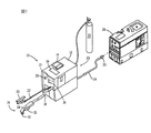
図1は、本発明に係るプラズマ切断装置10である。プラズマ切断装置10は、典型的には約230直流電圧ボルト(VDC)から300超過VDCまでの範囲の開回路出力電圧を有する高電圧装置である。プラズマ切断装置10は、原電力を調節しプラズマ切断仕様に対して適切な電力信号を発生する電力源12を含む。電力源12は、フィードバック信号を受け取りプラズマ切断装置10の作動を監視するプロセッサ13を含む。電力源12は、ある場所から別の場所へ搬送するのに役立つハンドル14を含む。トーチ16が、ケーブル18を介して電力源12と接続されている。ケーブル18は、トーチ16に電力と圧縮エアまたはガスを供給し、さらにトーチ16と電力源12との間の情報伝達線の役割を果たす。トーチ16は、引き金31とハンドル部から伸びる作業チップ32を有するハンドル部29またはトーチボディを含む。トーチ16に装着されて図示されているが、引き金31は、電力源12に接続されるかあるいはトーチ16に対して遠隔位置に配置されても良いことは、本発明の請求範囲内であることが理解されよう。
FIG. 1 shows a
また、被加工材用クランプ20が、電力源12に接続されている。クランプ20は、切断される被加工材(図示せず)と接続し、アース線またはリターン路を備えるよう設計されている。ケーブル22が、被加工材用クランプ20を、電力源12と接続している。ケーブル22は、被加工材と被加工材用クランプ20を通過するトーチ16からの切断電流用としてアース線またはリターン路を備えるよう設計されている。電力ケーブル24が、電力源12の後部23から伸びており、電力源12を可搬式電力供給器28か電力線コンセント(図示せず)のいずれかに接続するためのプラグ26を有している。電力源12は、オンオフ・スイッチ30を含み、電流計、エア圧調整器、表示ライト、圧力計36を含んでも良い。
A
切断を実行するために、トーチ16が、クランプ20に接続された被加工材の近くに置かれる。それから、ユーザーは、トーチ16上の引き金31を引き、電力と圧縮エアをトーチ16の作業チップ32へ供給し、パイロット・アーク(先立ち電弧)とプラズマジェットを発生させる。その後まもなく、ユーザーがトーチを被加工材へ動かし、切断アーク(電弧)が発生させられる。アークは、作業チップを通過し電極から被加工材へ移動する。ユーザーは、被加工材を横切ってトーチ16を移動させることにより被加工材を切断することができる。ユーザーは、火花スパッタを低減するために切断速度を調整しても良いし、電流かつ/またはエア圧を調整することによりさらに貫通した切断を実行しても良い。ガスは、内部エア圧縮機または外部エア圧縮機により、圧縮ガス源33からトーチ16へ供給される。
To perform the cutting, the
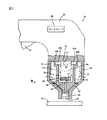
図2に、プラズマ切断トーチ16の消耗材組立体38が部分破断面で示されている。消耗品組立体38は、トーチ16のハンドル部29に装着されており、カソード部材または電極42、およびアノード部材またはチップ44を含む。電極42は、ガス室46内の中央に配置され、トーチ16のハンドル部29を介して電力源12と電気的に接続するベース47を有する。電極42は、電極42のベース47と反対側の端51に電極チップ49を含む。プラズマ形成ガス43は、スワールリング(図示せず)を通過し、複数の通路45Aからガス室46へ供給される。ガス43は、チップ44の最終部48を通過してガス室46から出る。別の複数のガス通路45Bは、シールド・ガス53をシールド・ガス通路50へ供給する。シールド・ガス通路50は、チップ44と、カップまたはキャップ52と、消耗品組立体38のキャップ52とつながるシールド55と、の間を延びている。
In FIG. 2, the
切断加工時、プラズマジェットは、チップ44の最終部48を通過して、シールド55のテーパ付き開口62を通過して、トーチ16から出る。シールド・ガスの流れもまた、シールド55のテーパ付き開口62を通過して、トーチ16から出て、通常プラズマジェットを包囲する。チップ44の最終部48と開口62は、協働してプラズマ流をプラズマ室64から集中した高密度のプラズマ流へと指向させる。プラズマ室64は、電極42とチップ44の最終部48の間のスペースに形成される。
During the cutting process, the plasma jet passes through the
パイロット・アークは、通常、プラズマ室64内で、全体として接点として知られる、電極42とチップ44との間で形成される。トーチを通過するガス流れは、パイロット・アークを発生させるプラズマジェットへ変換される。図示のごとく、電極42は、プラズマトーチ16のアイドルまたは非作動時に電極42がチップ44と接触するように、チップ44に対して移動可能である。引き金31の起動により電流とエア流れが発生する。エア流れは、電極42とチップ44との間を分離し、電流と協働し電極42とチップ44との間でパイロット・アークを形成する。ガス室46を通過するガス43は、パイロット・アークをチップ44のノズル部48とシールド55の開口62を通過して、被加工材54へと向けさせる。
The pilot arc is typically formed in the
トーチは、図示以外の要素の接触/分離を介してパイロット・アークを形成するように構築することもできることは理解されるであろうし特許請求の範囲内の思想でもある。例えば、プラズマトーチは、電極、チップ、ノズル、スワールリング、キャップの一部のいかなる組み合わせの間でも、接触/分離を介してパイロット・アークを発生させることができる。本発明は、「接触スタート」トーチであることよりもむしろ、高周波かつ/または高電圧スタート・トーチに共通して関連するものに対して等しく応用可能であることがさらに理解できよう。 It will be understood that the torch can be constructed to form a pilot arc through contact / separation of elements other than those shown, and is within the scope of the claims. For example, a plasma torch can generate a pilot arc through contact / separation between any combination of electrodes, tips, nozzles, swirl rings, and caps. It will be further appreciated that the present invention is equally applicable to what is commonly associated with high frequency and / or high voltage start torches, rather than being a “contact start” torch.
切断作業時、パイロット・アークから始まる切断アークは、被加工材54と電極42のインサート56との間で保持される。切断アークは、インサート56の端57の回りを渦巻き、トーチ16からのプラズマ流れ内で被加工材54へと進む。インサート56は、導電性を持ち、その回りを渦巻くアークの高温高電力に関連する劣化に耐えるように構成されている。インサート56は、所定の好ましい電気、熱、化学特性を表示し、好ましくはハフニウムまたはジルコニウムをベースとした金属から形成される。
During the cutting operation, a cutting arc starting from the pilot arc is held between the workpiece 54 and the insert 56 of the electrode 42. The cutting arc swirls around the
インサート56は、高い導電性を持ち、その回りを渦巻くプラズマアークに関連する劣化や磨耗に耐えるように構成されているが、インサート56は磨耗に影響を受けないようになっている。プラズマ切断加工時、インサート56の端57は、インサート56の端57を溶解させる電流と温度の影響を受けている。インサートの溶解部は、溶解はしているが、インサート56と接続している。アークがしぼんだ後、接点は、次のアークを発生させるために接点を再構築する必要がある。トーチを通過する浮遊エアにより、接点は互いに係合することができる。アーク消滅後まもなく接点が接触を始める場合、インサート磨耗に有害な影響を与えるいくつかの形態がある。
The insert 56 is highly conductive and is configured to withstand the degradation and wear associated with the plasma arc swirling around it, but the insert 56 is not susceptible to wear. At the time of plasma cutting, the
一つの形態として、接点が再び接触を始めるのを可能にするエアのオフ操作は、電極のインサートを含むプラズマトーチの要素の冷却を妨げる。電極のインサートは、インサートの溶解部分が固化するために長さが必要である。第2の形態として、トーチを通過するエアのオフ操作と関連する圧力変化は、溶解部分がインサート56から吸い取られるか吹き飛ばされることを引き起こす可能性がある。第3の形態である、即時のアークの再構築と関連するインサート磨耗の悪影響は、接点の開閉に関連する機械力である。接点の作動により、インサート56の一部が除去されることが可能になる。図3を参照して以下に論ずるが、アークがしぼんだ後、次のアーク発生の前に、遅れが始まる。その時、引き金は、引かれたままであり、インサートの溶解部が固化するのを可能とする。このような制御された遅れは、アークが消滅した後のアーク発生に関連するインサート磨耗を低減する。 In one form, the air off operation that allows the contacts to begin contacting again prevents cooling of the elements of the plasma torch including the electrode inserts. The length of the electrode insert is necessary for the melted portion of the insert to solidify. As a second form, the pressure change associated with turning off the air passing through the torch can cause the melted portion to be sucked out or blown away from the insert 56. The adverse effect of insert wear associated with a third form, immediate arc reconstruction, is the mechanical force associated with opening and closing the contacts. Actuation of the contacts allows a portion of the insert 56 to be removed. As will be discussed below with reference to FIG. 3, after the arc is deflated, a delay begins before the next arc occurs. At that time, the trigger remains pulled, allowing the melted portion of the insert to solidify. Such controlled delay reduces the insert wear associated with arcing after the arc is extinguished.
プラズマトーチ16は、プラズマトーチ16の作動モードを制御するよう構成されたコントローラ68を含む。コントローラ68は、トーチ16の中へ組み込まれて図示されているが、電力源とプラズマトーチとの間を通過するケーブルに接続されているか、好ましくは電力源の中へ配置されても良いと理解される。エキスパンデッドメタル作動モード時、引き金31を1回引くことにより、アークは、パイロット・アークと切断アークとの間で繰り返し変更される。トーチ16が被加工材54に近い材質である時、切断アークが発生され、トーチ16に近い材料が無い時、トーチ16は、トーチ16内部でパイロット・アークを保持する。
The
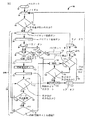
図3に、プラズマ切断装置を作動するためのテクニック80を示す。テクニック80は、電力源のオン操作のようなプラズマ切断装置の初期化82によりスタートする。プラズマ切断装置に電力を与えることにより、装置は、アイドルモード84に入る。アイドルモード84は、引き金を動かさないでオン操作を続行しながら、プラズマ切断装置の作動準備ができていることを表示する。86でプラズマ切断装置の引き金が引かれる時(88)、90で装置は、パイロット・アーク回路が作動可能となり、プラズマトーチがパイロット・アークを発生させ保持させることが可能となる。86で引き金が引かれない時(92)、プラズマ切断装置は、アイドルモード84で保持される。
FIG. 3 shows a
90でパイロット・アーク回路が作動可能になると、94でパイロット・アーク電流が、トーチの接点へ供給される。94においてパイロット・アーク電流は、パイロット・アークを保持し、切断アークを開始するのに十分なものである。すなわち、トーチが被加工材の近傍に置かれた時、パイロット・アーク電流の一部は、プラズマトーチと被加工材との間で初期切断アークを発生させるために十分なものとなる。本装置は、パイロット・アークの状態を監視して、電流が被加工材へのリード(導線)内に存在する時、または被加工材へのアーク伝達を表示するパイロット・アーク電流の変化が存在する時を決定する。 When the pilot arc circuit is enabled at 90, pilot arc current is provided at 94 to the torch contacts. At 94, the pilot arc current is sufficient to hold the pilot arc and initiate a cutting arc. That is, when the torch is placed in the vicinity of the workpiece, a portion of the pilot arc current is sufficient to generate an initial cutting arc between the plasma torch and the workpiece. This device monitors the condition of the pilot arc and when there is a current in the lead to the workpiece, or there is a change in the pilot arc current that indicates the arc transmission to the workpiece. Decide when to do.
本装置は、所定時間または中断時に(アーク)伝達が無い(100)時、パイロット・アークを保持するように構成されている。引き金の中断102に十分な時間において伝達無し(100)にパイロット・アークが保持される場合、本装置は、パイロット回路を作動不能にし、パイロット電流をオフにし、引き金をゆるめるのを待ち、以下に論ずる後流れ120へ向かう。中断102は、オペレータがプラズマ切断を実行する準備ができる前にトーチの引き金が引かれた時に利用される。好ましくは、オペレータがトーチの引き金を引き、パイロット・アークが発生し、パイロット・アークが3〜5秒間被加工材へ伝達されない場合、パイロット・アークは、消滅し、オペレータは、次のパイロット・アークを発生させるためプラズマトーチの引き金を再び引くことを要求される。または、パイロット・アークが構築されるまで、パイロット・アークが保持されることも可能である。 The apparatus is configured to hold the pilot arc when there is no (arc) transmission (100) during a predetermined time or interruption. If the pilot arc is held without transmission (100) for a time sufficient for trigger break 102, the device disables the pilot circuit, turns off the pilot current, waits to loosen the trigger, and so on. After the discussion, head to Flow 120. The break 102 is used when the torch is triggered before the operator is ready to perform a plasma cut. Preferably, if the operator triggers the torch, the pilot arc is generated and the pilot arc is not transmitted to the workpiece for 3-5 seconds, the pilot arc is extinguished and the operator To generate the plasma torch trigger again. Alternatively, the pilot arc can be held until the pilot arc is established.
パイロット・アークの伝達が検知された時(108)、ステップ90で作動可能となったパイロット・アーク回路は作動不能となり、112で切断電流がプラズマトーチに供給される。切断加工を実行するのに必要な電流は、アークを伝達するのに必要なパイロット・アーク電流より一般的に大きいと理解されている。当然、パイロット・アーク電流から切断電流への移行は、個々のユーザーや仕様に依存しており、それらに従って変化可能である。すなわち、特定のユーザーや仕様は、他のユーザーや仕様より迅速な応答を要求するかもしれない。従って、パイロット・アーク電流から切断アーク電流への移行は、おおむね瞬時、漸増、ランプ(傾斜)の各応答のいずれかであることが想像できよう。
When pilot arc transmission is detected (108), the pilot arc circuit enabled at
一旦、切断電流が供給されると(112)、本装置は、エキスパンデッドメタルモード(EMM)タイマを開始する(114)。タイマ114が稼動すると、本装置はプラズマトーチの引き金状態を監視する。タイマ114が開始した後、引き金が外されると(118)、加工80は、後流れ120においてトーチを通過するエア流れを維持する。後流れ120は、トーチを通過するガス流れを維持し、後流れが完了する前に引き金によるプラズマトーチの次に続く再スタートを可能にする。好ましくは、後流れ120により、引き金が外されてから5〜20秒間、エアがトーチを通過して流れる。トーチを通過するエア流れを維持することにより、切断作業の後、トーチを迅速に冷却することが可能となる。後流れ120の完了で、エア流れはオフされ(122)、これにより接点は互いに再係合が可能となり、プラズマトーチを、次のプラズマ切断加工のためにアイドルモード84へ戻すこととなる。次に続くプラズマ切断加工は、アークを再構築するために引き金操作88を必要とする。
Once the cutting current is supplied (112), the apparatus starts an expanded metal mode (EMM) timer (114). When the
引き金が外されない場合(124)、切断アークがアーク停止直前かどうかを監視する(126)。アーク停止直前126は、切断アークの電流、切断アーク電力信号により経験される抵抗、その他のプラズマトーチ操作パラメータの変化から決定することができる。切断アークのしぼみ直前が検知されれば(128)、パイロット・アーク回路が作動可能となり(90)、切断アークがパイロット・アーク状態へ変換されることが可能となる。切断アークのしぼみまたは停止128の前にパイロット・アーク回路が作動可能となることにより(90)、アークの完全な消失、またはしぼみ、または消滅は、切断アークをパイロット・アークへ変換することにより避けられる。アーク停止直前が検知されない場合(130)、本装置は、タイマ114が要求エキスパンデッドメタル切断時間を超過しているか否かをチェックする(132)。タイマ114が要求エキスパンデッドメタル切断時間を超過していなかった場合(134)、本装置は、引き金位置を監視するステップ(116)へリターンする。好ましくは、要求EMM切断時間は、約3秒間である。すなわち、切断アークが少なくとも3秒間維持されない場合、本装置は、プラズマトーチの引き金を再操作することなく切断アークをパイロット・アークへ変換することを可能とする。EMM切断時間の3秒間は、単に典型例であり、他の時間を要求しても良い。エキスパンデッドメタルモード136は、切断アークがエキスパンデッドメタル切断時間より長く(138)維持されるまで、引き金の単一操作状態で(88)パイロット・アーク状態と切断アーク状態との間でアークの繰り返し変換を可能にする。
If the trigger is not removed (124), it is monitored whether the cutting arc is just before arc stop (126). Immediately before the arc stop 126 can be determined from changes in the cutting arc current, the resistance experienced by the cutting arc power signal, and other plasma torch operating parameters. If just before the cutting arc is deflated (128), the pilot arc circuit is enabled (90) and the cutting arc can be converted to a pilot arc condition. By enabling the pilot arc circuit prior to cutting arc deflation or stop 128 (90), complete extinction, or deflation, or extinction of the arc is avoided by converting the cutting arc into a pilot arc. It is done. If an immediately preceding arc stop is not detected (130), the device checks whether the
所定時間後、エキスパンデッドメタルモードから通常の切断モードへの自動スイッチによる切替えにより、プラズマ切断装置の作動モードの制御は、ユーザーの要求出力に基づいて自動制御されることが可能となる。なぜなら、エキスパンデッドメタルは、一般に軽い規格材料であり、中実の材料より低い切断電流で良いからである。オペレータの要求出力の選択を監視することにより、コントローラは、ユーザーの要求出力に基づいてプラズマ切断装置の作動モードを制御することが可能となる。 After a predetermined time, the operation mode of the plasma cutting apparatus can be automatically controlled based on the output requested by the user by switching from the expanded metal mode to the normal cutting mode by an automatic switch. This is because expanded metal is generally a light standard material and requires a lower cutting current than a solid material. By monitoring the selection of the operator's required output, the controller can control the operating mode of the plasma cutting device based on the user's required output.
切断アークが、要求エキスパンデッドメタルモード時間より長く維持された後(138)、または出力が要求出力から許容誤差を超えて外れる場合、本装置は、エキスパンデッドメタルモード136を出て、非エキスパンデッドメタルモードまたはソリッドメタルモード140に入る。ソリッドメタルモード140において、切断アークは、切断が完了するまで維持され、トーチは被加工材から再移動され引き金が外される。本装置は、引き金状態を監視し(144)、引き金が外された時(146)、加工プロセスはプラズマ切断電流を作動不能にし後流れ120に入る。前述したように、後流れ120は、アークがしぼんだ後もトーチを通過するエア流れを続行し、トーチの内部要素を冷却する。引き金が外されず(148)、アーク停止が検知されない場合(150、152)、引き金が外される(144、146)かアークのしぼみが検知される(150、154)まで、切断アークは維持される(142)。
After the cutting arc is maintained longer than the required expanded metal mode time (138), or if the output deviates from the required output beyond tolerance, the device exits expanded
アークがしぼみ(154)引き金が外されていない場合(148)、制御された遅れが開始する(156)。制御された遅れ156の時、アーク電流は作動不能であるが、トーチを通過するエア流れは所定時間維持される。好ましくは、遅れ156の時間は、約0.5秒である。当然、他の時間も利用可能であり、考慮される。遅れ156の時間中にプラズマトーチを通過するエア流れを維持することにより、プラズマトーチの接点の分離が維持される。トーチを通過するエア流れと関連して、接点を閉じるのを遅らすことにより、切断作動時に溶解したインサートの一部を接点が閉鎖する前に固化させることが可能となる。このような構成により、アークがしぼんだ後に引き金が外されていない時、消耗材たる電極のインサートにより経験される磨耗が低減する。
If the arc is deflated (154) and the trigger is not removed (148), a controlled delay is initiated (156). At the controlled
遅れ156の後、プラズマトーチを通過するエアをオフする(158)。これにより、接点が閉じるか係合された配置へ戻ることが可能となる。引き金がまだ引かれており(154)、遅れ156が実行され、エアがオフされる(158)と、本装置は、パイロット・アーク回路が再び作動可能となる(90)。これにより、プラズマトーチが次のアークを発生することが可能となる。
After the
上述したテクニック80により、引き金を再び引くこと無しに初期アークがしぼんだ後に次のアークを発生させることが可能となる。さらに、本発明に係るプラズマ切断装置は、プラズマ切断装置の作動を自動的に切換え、アークを、エキスパンデッドメタル作動モードと、非エキスパンデッドまたはソリッドメタル作動モードと、の間で繰り返し変換することを可能にする。エキスパンデッドメタル作動モードは、パイロット・アーク状態と切断アーク状態とを切換え、非エキスパンデッドまたはソリッドメタル作動モードは、アーク消滅とアーク構築を単一の引き金作動により可能にする(これにより、パイロット・アークも切断アークも存在しない)。このような加工プロセスは、複数の作動モードの間でプラズマ切断装置を自動的に非機械的に切り換える。
The
さらに、引続き切断作業をオペレータが要求することを示すために、アークが消滅した後に引き金が係合されたままの時、プラズマトーチの接点の再係合を遅らせることにより加工プロセスは、消耗材組立体のインサートにより経験される磨耗を低減させる。このような構成により、インサートのいかなる溶解部も、次のアークの発生前に固化させることが可能となる。これにより、接点の移動や次のアーク発生と関連するインサートの磨耗が低減される。 Further, to indicate that the operator still requires a cutting operation, the machining process can be performed by delaying the re-engagement of the plasma torch contacts when the trigger remains engaged after the arc is extinguished. Reduces the wear experienced by solid inserts. With such a configuration, any melted portion of the insert can be solidified before the next arc occurs. This reduces insert wear associated with contact movement and subsequent arcing.
それゆえ、本発明に係る一実施形態は、エキスパンデッドメタルモードと非エキスパンデッドメタルモードとの間でプラズマトーチの作動を自動的に切換えるように構成されたコントローラと、トーチと、を有する溶接型装置を含む。 Therefore, one embodiment according to the present invention comprises a controller configured to automatically switch the operation of a plasma torch between an expanded metal mode and a non-expanded metal mode, and a torch. Includes welding type equipment.
本発明に係る別の実施形態は、プラズマ切断電力を発生させる電力源と、電力源と接続されたプラズマトーチと、を有するプラズマ切断装置を含む。プラズマ切断装置は、第1切断モードと第2切断モードで作動可能であり、プラズマトーチの作動を第1切断モードと第2切断モードの間で非機械的に変更するソフトウエア手段を含む。 Another embodiment according to the present invention includes a plasma cutting device having a power source for generating plasma cutting power and a plasma torch connected to the power source. The plasma cutting device is operable in a first cutting mode and a second cutting mode, and includes software means for non-mechanically changing the operation of the plasma torch between the first cutting mode and the second cutting mode.
本発明に係るさらなる別の実施形態は、プラズマトーチ装置のコントローラを含む。このコントローラは、プラズマトーチのアーク作動時間を監視し、切断アーク作動時間が所定時間を超過していない場合は切断アークをパイロット・アークへ変換させ、切断アーク作動時間が少なくとも所定時間の場合は切断アークをしぼませる。 Yet another embodiment according to the present invention includes a controller for a plasma torch device. The controller monitors the arc operating time of the plasma torch, converts the cutting arc to a pilot arc if the cutting arc operating time does not exceed the predetermined time, and cuts if the cutting arc operating time is at least the predetermined time Squeeze the arc.
当業者は、以下のことを十分に認識しているはずである。すなわち、前述のプラズマ切断装置は、本発明に係るプラズマ切断装置の一例である。提示された以外のアーク開始テクニックを有するトーチも想像可能であり本願請求範囲内である。 Those skilled in the art should be fully aware of the following: That is, the above-described plasma cutting apparatus is an example of the plasma cutting apparatus according to the present invention. A torch having an arc initiation technique other than that presented is also conceivable and within the scope of the claims.
本発明は、好適な実施形態を用いて以上のごとく記述された。この記述例から外れた等価例、選択可能例、変形例が可能であり、添付の本願請求範囲に含まれる。 The present invention has been described above using preferred embodiments. Equivalent examples, selectable examples, and modified examples deviating from this description example are possible, and are included in the appended claims.
Claims (7)
電力源に接続され第1切断モードと第2切断モードで操作可能なプラズマトーチと、
第1切断モードと第2切断モードの間でプラズマトーチの作動を非機械的に変更するためのソフトウエア手段と、を備えたことを特徴とするプラズマ切断装置。 A power source configured to generate plasma cutting power;
A plasma torch connected to a power source and operable in a first cutting mode and a second cutting mode;
And a software means for non-mechanically changing the operation of the plasma torch between the first cutting mode and the second cutting mode.
前記電極と前記接触器との間を分離させることにより電気アークを発生させることを特徴とする、請求項1に記載のプラズマ切断装置。 It further comprises one electrode and one contactor,
The plasma cutting device according to claim 1, wherein an electric arc is generated by separating the electrode and the contactor.
Applications Claiming Priority (1)
| Application Number | Priority Date | Filing Date | Title |
|---|---|---|---|
| US10/905,418 US8263896B2 (en) | 2005-01-03 | 2005-01-03 | Automated determination of plasma torch operating mode |
Publications (1)
| Publication Number | Publication Date |
|---|---|
| JP2006187807A true JP2006187807A (en) | 2006-07-20 |
Family
ID=36127277
Family Applications (1)
| Application Number | Title | Priority Date | Filing Date |
|---|---|---|---|
| JP2005379182A Pending JP2006187807A (en) | 2005-01-03 | 2005-12-28 | Automatic determination of plasma torch operation mode |
Country Status (5)
| Country | Link |
|---|---|
| US (1) | US8263896B2 (en) |
| EP (1) | EP1676665B1 (en) |
| JP (1) | JP2006187807A (en) |
| CA (1) | CA2530847A1 (en) |
| DE (1) | DE602005008000D1 (en) |
Families Citing this family (40)
| Publication number | Priority date | Publication date | Assignee | Title |
|---|---|---|---|---|
| US8764978B2 (en) | 2001-07-16 | 2014-07-01 | Foret Plasma Labs, Llc | System for treating a substance with wave energy from an electrical arc and a second source |
| US9761413B2 (en) | 2007-10-16 | 2017-09-12 | Foret Plasma Labs, Llc | High temperature electrolysis glow discharge device |
| US8278810B2 (en) | 2007-10-16 | 2012-10-02 | Foret Plasma Labs, Llc | Solid oxide high temperature electrolysis glow discharge cell |
| US9516736B2 (en) | 2007-10-16 | 2016-12-06 | Foret Plasma Labs, Llc | System, method and apparatus for recovering mining fluids from mining byproducts |
| US11806686B2 (en) | 2007-10-16 | 2023-11-07 | Foret Plasma Labs, Llc | System, method and apparatus for creating an electrical glow discharge |
| US9185787B2 (en) | 2007-10-16 | 2015-11-10 | Foret Plasma Labs, Llc | High temperature electrolysis glow discharge device |
| US8810122B2 (en) | 2007-10-16 | 2014-08-19 | Foret Plasma Labs, Llc | Plasma arc torch having multiple operating modes |
| US9051820B2 (en) | 2007-10-16 | 2015-06-09 | Foret Plasma Labs, Llc | System, method and apparatus for creating an electrical glow discharge |
| US9560731B2 (en) | 2007-10-16 | 2017-01-31 | Foret Plasma Labs, Llc | System, method and apparatus for an inductively coupled plasma Arc Whirl filter press |
| US9445488B2 (en) | 2007-10-16 | 2016-09-13 | Foret Plasma Labs, Llc | Plasma whirl reactor apparatus and methods of use |
| US9230777B2 (en) | 2007-10-16 | 2016-01-05 | Foret Plasma Labs, Llc | Water/wastewater recycle and reuse with plasma, activated carbon and energy system |
| US10267106B2 (en) | 2007-10-16 | 2019-04-23 | Foret Plasma Labs, Llc | System, method and apparatus for treating mining byproducts |
| AU2009214660B2 (en) | 2008-02-12 | 2013-01-17 | Foret Plasma Labs, Llc | System, method and apparatus for lean combustion with plasma from an electrical arc |
| US8904749B2 (en) | 2008-02-12 | 2014-12-09 | Foret Plasma Labs, Llc | Inductively coupled plasma arc device |
| US10244614B2 (en) | 2008-02-12 | 2019-03-26 | Foret Plasma Labs, Llc | System, method and apparatus for plasma arc welding ceramics and sapphire |
| US20110180517A1 (en) * | 2010-01-26 | 2011-07-28 | Illinois Tool Works Inc. | Methods and systems for binding a wireless control device to a welding power source |
| US10455682B2 (en) | 2012-04-04 | 2019-10-22 | Hypertherm, Inc. | Optimization and control of material processing using a thermal processing torch |
| US9481050B2 (en) | 2013-07-24 | 2016-11-01 | Hypertherm, Inc. | Plasma arc cutting system and persona selection process |
| US9782852B2 (en) | 2010-07-16 | 2017-10-10 | Hypertherm, Inc. | Plasma torch with LCD display with settings adjustment and fault diagnosis |
| US10486260B2 (en) | 2012-04-04 | 2019-11-26 | Hypertherm, Inc. | Systems, methods, and devices for transmitting information to thermal processing systems |
| US20140203005A1 (en) * | 2013-01-23 | 2014-07-24 | Gordon R. Hanka | Welder powered arc starter |
| US20160121418A1 (en) * | 2012-01-25 | 2016-05-05 | Gordon Hanka | Welder Powered Arc Starter |
| US9737954B2 (en) | 2012-04-04 | 2017-08-22 | Hypertherm, Inc. | Automatically sensing consumable components in thermal processing systems |
| US9672460B2 (en) | 2012-04-04 | 2017-06-06 | Hypertherm, Inc. | Configuring signal devices in thermal processing systems |
| US11783138B2 (en) | 2012-04-04 | 2023-10-10 | Hypertherm, Inc. | Configuring signal devices in thermal processing systems |
| US20150332071A1 (en) | 2012-04-04 | 2015-11-19 | Hypertherm, Inc. | Configuring Signal Devices in Thermal Processing Systems |
| US9395715B2 (en) | 2012-04-04 | 2016-07-19 | Hypertherm, Inc. | Identifying components in a material processing system |
| US9144882B2 (en) | 2012-04-04 | 2015-09-29 | Hypertherm, Inc. | Identifying liquid jet cutting system components |
| MX340051B (en) * | 2012-10-01 | 2016-06-22 | Foret Plasma Labs Llc | Plasma arc torch having multiple operation modes. |
| CA2894535C (en) | 2012-12-11 | 2018-05-29 | Foret Plasma Labs, Llc | High temperature countercurrent vortex reactor system, method and apparatus |
| EP2971488B1 (en) | 2013-03-12 | 2018-09-26 | Foret Plasma Labs, Llc | Apparatus and method for sintering proppants |
| US10471666B2 (en) | 2013-10-04 | 2019-11-12 | Kanawha Automation, Llc | Dynamic additive manufacturing system |
| US9643273B2 (en) | 2013-10-14 | 2017-05-09 | Hypertherm, Inc. | Systems and methods for configuring a cutting or welding delivery device |
| US12521905B2 (en) | 2014-03-07 | 2026-01-13 | Hypertherm, Inc. | Liquid pressurization pump and systems with data storage |
| US9993934B2 (en) | 2014-03-07 | 2018-06-12 | Hyperthem, Inc. | Liquid pressurization pump and systems with data storage |
| US10786924B2 (en) | 2014-03-07 | 2020-09-29 | Hypertherm, Inc. | Waterjet cutting head temperature sensor |
| US20150269603A1 (en) | 2014-03-19 | 2015-09-24 | Hypertherm, Inc. | Methods for Developing Customer Loyalty Programs and Related Systems and Devices |
| US11267069B2 (en) | 2018-04-06 | 2022-03-08 | The Esab Group Inc. | Recognition of components for welding and cutting torches |
| US10625359B2 (en) | 2018-04-06 | 2020-04-21 | The Esab Group Inc. | Automatic identification of components for welding and cutting torches |
| USD914071S1 (en) | 2018-11-02 | 2021-03-23 | Esab Ab | Welding device enclosure |
Family Cites Families (7)
| Publication number | Priority date | Publication date | Assignee | Title |
|---|---|---|---|---|
| US5070227A (en) * | 1990-04-24 | 1991-12-03 | Hypertherm, Inc. | Proceses and apparatus for reducing electrode wear in a plasma arc torch |
| US5620617A (en) * | 1995-10-30 | 1997-04-15 | Hypertherm, Inc. | Circuitry and method for maintaining a plasma arc during operation of a plasma arc torch system |
| US5630954A (en) * | 1995-12-19 | 1997-05-20 | The Esab Group, Inc. | Digital meter for cutting or welding system and method of displaying digital data for same |
| US5831237A (en) * | 1997-03-13 | 1998-11-03 | The Lincoln Electric Company | Plasma arc power system and method of operating same |
| US6133543A (en) * | 1998-11-06 | 2000-10-17 | Hypertherm, Inc. | System and method for dual threshold sensing in a plasma ARC torch |
| GB9825452D0 (en) * | 1998-11-21 | 1999-01-13 | Arc Kinetics Ltd | Improved welding apparatus and method |
| US6794601B2 (en) | 2002-09-05 | 2004-09-21 | Thermal Dynamics Corporation | Plasma arc torch system with pilot re-attach circuit and method |
-
2005
- 2005-01-03 US US10/905,418 patent/US8263896B2/en active Active
- 2005-12-16 EP EP05257752A patent/EP1676665B1/en not_active Expired - Lifetime
- 2005-12-16 DE DE602005008000T patent/DE602005008000D1/en not_active Expired - Fee Related
- 2005-12-19 CA CA002530847A patent/CA2530847A1/en not_active Abandoned
- 2005-12-28 JP JP2005379182A patent/JP2006187807A/en active Pending
Also Published As
| Publication number | Publication date |
|---|---|
| EP1676665A3 (en) | 2006-12-13 |
| DE602005008000D1 (en) | 2008-08-21 |
| CA2530847A1 (en) | 2006-07-03 |
| EP1676665A2 (en) | 2006-07-05 |
| EP1676665B1 (en) | 2008-07-09 |
| US20060151445A1 (en) | 2006-07-13 |
| US8263896B2 (en) | 2012-09-11 |
Similar Documents
| Publication | Publication Date | Title |
|---|---|---|
| US8263896B2 (en) | Automated determination of plasma torch operating mode | |
| JP2006187808A (en) | Method and apparatus for conserving plasma torch consumable | |
| CA2225942C (en) | Plasma pilot arc control | |
| CN100475416C (en) | Method and device for combined laser-arc welding with control of laser unit according to welding torch | |
| JP2623329B2 (en) | How to use arc plasma torch and contact start | |
| WO2007114882A1 (en) | Plasma torch with post flow control | |
| JPH06652A (en) | Plasma arc torch power release mechanism | |
| JP2011082146A (en) | Plasma torch having electrode wear detection system | |
| JPH029917B2 (en) | ||
| FR2562453A1 (en) | VERY LOW POWER PLASMA CUTTING EQUIPMENT | |
| US20030164359A1 (en) | Solenoid control and safety circuit system and method | |
| JP4391869B2 (en) | Plasma torch | |
| US6933463B2 (en) | Main arc ignition device and main arc ignition control method of plasma cutting machine | |
| CA2454809C (en) | Method and apparatus for initiating welding arc using plasma jet | |
| CN107639329B (en) | System and method for plasma arc transfer for plasma cutting | |
| CN111545883A (en) | Cutting machine control method and control device | |
| CN101288347B (en) | Operation method of steam plasma burner and steam cutting equipment | |
| JP2013237095A (en) | Plasma cutting torch and plasma arc cutting apparatus | |
| JPH05245634A (en) | Method and device for reigniting arc in shielding gas welding process | |
| US3354289A (en) | Method of increasing the durability of nozzles for arc-plasma-torches with high power density and a connection arrangement for carrying out the process | |
| JP4468542B2 (en) | Air plasma cutting machine | |
| JPH0394982A (en) | Plasma arc machine | |
| SU1704977A1 (en) | Apparatus for arc welding | |
| JP3220616B2 (en) | Plasma arc transfer type cutting device | |
| JPH079153A (en) | Control method of plasma cutting device |