JP2006281176A - Thin film forming apparatus - Google Patents
Thin film forming apparatus Download PDFInfo
- Publication number
- JP2006281176A JP2006281176A JP2005108506A JP2005108506A JP2006281176A JP 2006281176 A JP2006281176 A JP 2006281176A JP 2005108506 A JP2005108506 A JP 2005108506A JP 2005108506 A JP2005108506 A JP 2005108506A JP 2006281176 A JP2006281176 A JP 2006281176A
- Authority
- JP
- Japan
- Prior art keywords
- support
- thin film
- forming apparatus
- film forming
- coating liquid
- Prior art date
- Legal status (The legal status is an assumption and is not a legal conclusion. Google has not performed a legal analysis and makes no representation as to the accuracy of the status listed.)
- Pending
Links
- 239000010409 thin film Substances 0.000 title claims abstract description 69
- 238000000576 coating method Methods 0.000 claims abstract description 120
- 239000011248 coating agent Substances 0.000 claims abstract description 119
- 239000010408 film Substances 0.000 claims abstract description 74
- 239000007788 liquid Substances 0.000 claims abstract description 57
- 238000009736 wetting Methods 0.000 claims abstract description 16
- 208000028659 discharge Diseases 0.000 claims description 36
- 238000000034 method Methods 0.000 claims description 20
- 239000002904 solvent Substances 0.000 claims description 18
- 239000000428 dust Substances 0.000 claims description 16
- 238000010438 heat treatment Methods 0.000 claims description 15
- 239000000463 material Substances 0.000 claims description 15
- 238000003851 corona treatment Methods 0.000 claims description 14
- 230000003746 surface roughness Effects 0.000 claims description 12
- 238000007599 discharging Methods 0.000 claims description 10
- 238000012545 processing Methods 0.000 claims description 9
- 238000009501 film coating Methods 0.000 claims description 3
- 239000004973 liquid crystal related substance Substances 0.000 claims description 3
- 239000007888 film coating Substances 0.000 claims description 2
- 239000000243 solution Substances 0.000 description 19
- 238000005259 measurement Methods 0.000 description 8
- 230000003068 static effect Effects 0.000 description 7
- 238000003860 storage Methods 0.000 description 5
- 230000015572 biosynthetic process Effects 0.000 description 4
- 238000009826 distribution Methods 0.000 description 4
- 230000005611 electricity Effects 0.000 description 4
- 238000002360 preparation method Methods 0.000 description 4
- 238000004528 spin coating Methods 0.000 description 4
- ZWEHNKRNPOVVGH-UHFFFAOYSA-N 2-Butanone Chemical compound CCC(C)=O ZWEHNKRNPOVVGH-UHFFFAOYSA-N 0.000 description 3
- XEKOWRVHYACXOJ-UHFFFAOYSA-N Ethyl acetate Chemical compound CCOC(C)=O XEKOWRVHYACXOJ-UHFFFAOYSA-N 0.000 description 3
- KFZMGEQAYNKOFK-UHFFFAOYSA-N Isopropanol Chemical compound CC(C)O KFZMGEQAYNKOFK-UHFFFAOYSA-N 0.000 description 3
- MPIAGWXWVAHQBB-UHFFFAOYSA-N [3-prop-2-enoyloxy-2-[[3-prop-2-enoyloxy-2,2-bis(prop-2-enoyloxymethyl)propoxy]methyl]-2-(prop-2-enoyloxymethyl)propyl] prop-2-enoate Chemical compound C=CC(=O)OCC(COC(=O)C=C)(COC(=O)C=C)COCC(COC(=O)C=C)(COC(=O)C=C)COC(=O)C=C MPIAGWXWVAHQBB-UHFFFAOYSA-N 0.000 description 3
- 230000008030 elimination Effects 0.000 description 3
- 238000003379 elimination reaction Methods 0.000 description 3
- 238000004519 manufacturing process Methods 0.000 description 3
- 239000002184 metal Substances 0.000 description 3
- -1 polyethylene Polymers 0.000 description 3
- 238000011101 absolute filtration Methods 0.000 description 2
- 238000004140 cleaning Methods 0.000 description 2
- 238000001035 drying Methods 0.000 description 2
- 230000003287 optical effect Effects 0.000 description 2
- 238000005498 polishing Methods 0.000 description 2
- 238000012546 transfer Methods 0.000 description 2
- XLYOFNOQVPJJNP-UHFFFAOYSA-N water Substances O XLYOFNOQVPJJNP-UHFFFAOYSA-N 0.000 description 2
- 238000004804 winding Methods 0.000 description 2
- WWMFRKPUQJRNBY-UHFFFAOYSA-N (2,3-dimethoxyphenyl)-phenylmethanone Chemical compound COC1=CC=CC(C(=O)C=2C=CC=CC=2)=C1OC WWMFRKPUQJRNBY-UHFFFAOYSA-N 0.000 description 1
- 239000004698 Polyethylene Substances 0.000 description 1
- 239000004743 Polypropylene Substances 0.000 description 1
- 238000009529 body temperature measurement Methods 0.000 description 1
- 238000009835 boiling Methods 0.000 description 1
- 238000011109 contamination Methods 0.000 description 1
- 238000006073 displacement reaction Methods 0.000 description 1
- 230000000694 effects Effects 0.000 description 1
- 230000007613 environmental effect Effects 0.000 description 1
- 238000011156 evaluation Methods 0.000 description 1
- 239000011521 glass Substances 0.000 description 1
- 238000002347 injection Methods 0.000 description 1
- 239000007924 injection Substances 0.000 description 1
- 239000011229 interlayer Substances 0.000 description 1
- 239000000203 mixture Substances 0.000 description 1
- 239000000178 monomer Substances 0.000 description 1
- 229920002120 photoresistant polymer Polymers 0.000 description 1
- 230000000704 physical effect Effects 0.000 description 1
- 229920000573 polyethylene Polymers 0.000 description 1
- 229920000139 polyethylene terephthalate Polymers 0.000 description 1
- 239000005020 polyethylene terephthalate Substances 0.000 description 1
- 229920001155 polypropylene Polymers 0.000 description 1
- 230000001681 protective effect Effects 0.000 description 1
- 239000004065 semiconductor Substances 0.000 description 1
- 239000000758 substrate Substances 0.000 description 1
- 239000004094 surface-active agent Substances 0.000 description 1
- 238000012360 testing method Methods 0.000 description 1
- 239000013638 trimer Substances 0.000 description 1
Images


Landscapes
- Coating Apparatus (AREA)
Abstract
Description
本発明は、溶剤中に膜材料が溶解又は分散させられてなる塗布液を帯状支持体上に塗布して薄膜を形成する薄膜形成装置に関する。 The present invention relates to a thin film forming apparatus that forms a thin film by applying a coating solution in which a film material is dissolved or dispersed in a solvent onto a belt-like support.
従来、薄膜形成技術としては、例えば薄膜塗布法の一つであるスピンコート法が一般的に用いられている。このスピンコート法は、塗布液を帯状支持体上に滴下した後に、帯状支持体を回転させて遠心力により帯状支持体全面に塗布を行って薄膜を形成する方法であり、回転数及び回転保持時間、あるいは塗布液の粘度などにより膜厚を制御するものである。このスピンコート法は、例えば半導体製造工程等に用いられるフォトレジスト膜やSOG(スピンオンガラス)等の層間絶縁膜の形成、液晶装置製造工程等におけるオーバーコート膜(平坦化膜)や配向膜の形成、さらには光ディスク等の製造工程における保護膜の形成等に広く用いられている。
しかしながら、このスピンコート法では、帯状支持体に連続して塗布することができず、毎回塗布支持体を取り替える必要があり、多くの塗布液を供給する必要があるとともに無駄が多く、生産コストが高くなるといった不都合があった。これらの対策のため、近年、いわゆるインクジェット法を応用した技術が提案されている。
例えば、特許文献1にはインクジェット法を応用して帯状支持体上に塗布液を塗布し、薄膜を形成する技術が記載されている。この技術は、相対移動手段によってヘッドを帯状支持体に対して直線的に相対移動させ、これによって塗布液を角型帯状支持体上に均一に塗布できるようにしたものである。
また、特許文献2には同じくインクジェット法を応用し、溶剤中に膜材料が溶解又は分散させられてなる塗布液Lを基板SUB上に塗布して薄膜を形成する薄膜形成装置であり、塗布された塗布液の近傍に溶剤蒸気を供給する溶剤蒸気供給機構を有することにより均一に塗布できるようにしたものであることが記載されている。
However, in this spin coating method, it is not possible to continuously apply to the belt-like support, and it is necessary to replace the application support every time. There was inconvenience that it became high. For these measures, in recent years, a technique using a so-called inkjet method has been proposed.
For example, Patent Document 1 describes a technique in which a thin film is formed by applying a coating liquid onto a belt-like support by applying an inkjet method. In this technique, the head is linearly moved relative to the belt-like support by relative movement means, whereby the coating liquid can be uniformly applied onto the rectangular belt-like support.
Also, Patent Document 2 is a thin film forming apparatus that similarly applies the ink jet method and applies a coating liquid L in which a film material is dissolved or dispersed in a solvent to form a thin film on a substrate SUB. In addition, it is described that a solvent vapor supply mechanism for supplying solvent vapor in the vicinity of the coating liquid can be applied uniformly.
しかしながら、特許文献1及び2に記載の技術では、高生産性を得るために必要な連続して帯状支持体に高品位な塗布を実施できない。なぜなら帯状支持体に連続塗布をするためには、帯状支持体と一定速度で供給する巻き出し機や元巻きと元巻きの交換作業のために時間的な余裕を保持するためのアキュームレーター機、搬送する支持体の張力を安定させるためにダンサーロールやニップロール、これらの機器との間をつなぐ多数の搬送ロールが必要であり、ロールに接触するたびに支持体の表面の物理的な性質が変化する。たとえば、金属ロールに支持体が接触した後、金属ロールから剥離されると、剥離帯電により支持体表面の帯電量が変化する。
特に、高速での搬送性向上のために、搬送ロールの表面にマット加工を施したり、ロールの一部または全部溝きり加工することが知られているが、このような表面性が違うロールから剥離すると、表面状態の違いにより、帯電量は変化する。
また、搬送ロールからの伝熱により、搬送ロールに接触したあとの支持体表面温度が変化する。この場合も、前記高速での搬送性向上のために、搬送ロールの表面をマット加工や溝きり加工があると、表面状態の違いにより伝熱量が変化し、支持体の表面温度のバラツキを発生させる。
帯電量が高い支持体にインクジェット法を応用して帯状支持体上に塗布液を塗布し、薄膜を形成しようとすると、液滴吐出ヘッドから吐出される液滴が数ピコリットルと非常に小さいため、静電気により所定の着弾位置と異なる位置に着弾したり、ひどい場合には着弾自体しなくなり、均一な膜厚を得ることができないだけでなく、塗布機を汚染し、生産性が極端に劣化する。仮に着弾したとしてもその後レベリングが阻害され、膜厚分布が劣化し、配向ムラや色ムラが生じることがある。
However, the techniques described in Patent Documents 1 and 2 cannot continuously perform high-quality coating on a belt-like support necessary for obtaining high productivity. Because, in order to continuously apply to the belt-shaped support, an unwinding machine that supplies the belt-shaped support and a constant speed, and an accumulator machine for maintaining a time margin for replacement work between the original winding and the original winding, In order to stabilize the tension of the support to be transported, dancer rolls, nip rolls, and many transport rolls connecting these devices are required, and the physical properties of the surface of the support change with each contact with the roll. To do. For example, when the support is brought into contact with the metal roll and then peeled off from the metal roll, the charge amount on the support surface changes due to peeling charging.
In particular, in order to improve transportability at high speed, it is known that the surface of the transport roll is matted or part or all of the roll is grooved. When peeled off, the charge amount changes due to the difference in surface condition.
Moreover, the support body surface temperature after contacting a conveyance roll changes with the heat transfer from a conveyance roll. Also in this case, if the surface of the transport roll is matted or grooved to improve the transportability at high speeds, the amount of heat transfer will change due to the difference in surface condition, resulting in variations in the surface temperature of the support. Let
When applying a coating liquid on a belt-like support by applying the inkjet method to a support with a high charge amount, and forming a thin film, the droplets ejected from the droplet ejection head are very small, a few picoliters. In addition to landing at a position different from the predetermined landing position due to static electricity, or in severe cases, the landing itself will not occur, and not only a uniform film thickness cannot be obtained, but also the coating machine will be contaminated and the productivity will be extremely deteriorated . Even if it lands, the leveling is hindered thereafter, the film thickness distribution is deteriorated, and alignment unevenness and color unevenness may occur.
さらに支持体表面に帯電量が不均一な場合は、膜厚分布やこれに伴い発生する配向ムラや色ムラ等が発生する。
また、既に膜材料が形成された支持体表面に、更に別の膜材料を取り扱う場合は、搬送ロールにより既膜材料が剥がされたものが、ロールに転写後、支持体面に再付着しこの状態で液滴吐出ヘッドから吐出された液滴が支持体表面に均一につかないで点状の色ムラが発生する。
支持体表面温度についても、支持体表面温度が低下すると、着弾後の塗布液の粘度が上昇しレベリングを阻害することになり、膜厚分布が劣化し、配向ムラや色ムラが生じることがある。
同様に支持体表面の温度が不均一な場合もまた膜厚分布や、これに伴い発生する配向ムラや色ムラ等が発生する。これらを回避するために搬送ロールを改造することは非常にコストが高くなり、生産性が悪くなる。
Further, when the charge amount is not uniform on the surface of the support, the film thickness distribution, the alignment unevenness, the color unevenness, etc. that occur along with it occur.
In addition, when handling another film material on the surface of the support on which the film material has already been formed, the film already peeled off by the transport roll is transferred to the roll and then reattached to the support surface. As a result, the liquid droplets ejected from the liquid droplet ejection head are not uniformly applied to the surface of the support, and dot-like color unevenness occurs.
As for the support surface temperature, if the support surface temperature is lowered, the viscosity of the coating liquid after landing increases and the leveling is inhibited, and the film thickness distribution may be deteriorated, resulting in uneven alignment and uneven color. .
Similarly, when the temperature of the support surface is not uniform, the film thickness distribution, the alignment unevenness, the color unevenness, and the like that occur along with this also occur. In order to avoid these, it is very expensive to modify the transport roll, and the productivity is deteriorated.
本発明は、前記事情に鑑みてなされたもので、その目的とするところは、連続した帯状支持体に、液滴吐出ヘッドを用いることによって形成する膜全体の厚さを均一にすることができるようにした薄膜形成装置を提供することにある。 The present invention has been made in view of the above circumstances, and an object of the present invention is to make the thickness of the entire film formed uniform by using a droplet discharge head on a continuous belt-like support. An object of the present invention is to provide a thin film forming apparatus.
上記目的は下記構成により達成できる。
(請求項1)
溶剤中に膜材料が溶解又は分散させられてなる塗布液を支持体上に吐出する液滴吐出ヘッドを有する吐出機構から液滴を吐出することで塗布して薄膜を形成する薄膜形成装置において、
連続して供給される支持体の表面の濡れ張力が30〜70dyne/cmであり、かつ前記塗布液の表面張力が15〜50dyne/cmであり、前記支持体の表面の濡れ張力は前記塗布液の表面張力より高いことを特徴とする薄膜形成装置。
(請求項2)
前記支持体の表面濡れ張力を制御するコロナ放電処理手段を有することを特徴とする請求項1に記載の薄膜形成装置。
(請求項3)
コロナ放電処理を実施した位置から前記吐出機構まで、支持体の表面にロール接触がないことを特徴とする請求項1又は2に記載の薄膜形成装置。
(請求項4)
溶剤中に膜材料が溶解又は分散させられてなる塗布液を支持体上に吐出する液滴吐出ヘッドを有する吐出機構から液滴を吐出することで塗布して薄膜を形成する薄膜形成装置であって、
塗布液を塗布する直前の前記支持体の表面の帯電量が−1kV〜+1kVの範囲内になるように制御する制御手段を有することを特徴とする薄膜形成装置。
(請求項5)
前記支持体の表面の帯電量を制御する制御手段位置から前記吐出機構まで、支持体の表面にロール接触がないことを特徴とする請求項4に記載の薄膜形成装置。
(請求項6)
溶剤中に膜材料が溶解又は分散させられてなる塗布液を支持体上に吐出する液滴吐出ヘッドを有する吐出機構から液滴を吐出することで塗布して薄膜を形成する薄膜形成装置であって、
連続して供給される前記支持体の表面に均一な除電処置を施した後に、除塵処理を行う除塵処理手段を有することを特徴とする請求項4又は5に記載の薄膜形成装置。
(請求項7)
溶剤中に膜材料が溶解又は分散させられてなる塗布液を支持体上に吐出する液滴吐出ヘッドを有する吐出機構から液滴を吐出することで塗布して薄膜を形成する薄膜形成装置であって、
連続して供給される前記支持体の表面温度を20〜80℃の範囲内に加温する処理を行う加温手段を有することを特徴とする薄膜形成装置。
(請求項8)
加温処理を行う前記加温手段の位置から前記吐出機構まで、前記支持体の表面にロール接触がないことを特徴とする請求項7に記載の薄膜形成装置。
(請求項9)
溶剤中に膜材料が溶解又は分散させられてなる塗布液を支持体上に吐出する液滴吐出ヘッドを有する吐出機構から液滴を吐出することで塗布して薄膜を形成する薄膜形成装置であって、
連続して供給される前記支持体の表面粗さRaが0.01〜10μmであり、塗布膜厚が0.5〜50μmであり、支持体の表面粗さRaは塗布膜厚の0.1%〜10%であることを特徴とする薄膜形成装置。
(請求項10)
前記塗布液が反射防止膜フィルム用塗布液であることを特徴とする請求項1乃至9の何れか1項に記載の薄膜形成装置。
(請求項11)
前記塗布液が液晶ディスプレイフィルム用塗布液であることを特徴とする請求項1乃至9の何れか1項に記載の薄膜形成装置。
(請求項12)
前記塗布液が有機ELディスプレイフィルム用塗布液であることを特徴とする請求項1乃至9の何れか1項に記載の薄膜形成装置。
The above object can be achieved by the following constitution.
(Claim 1)
In a thin film forming apparatus that forms a thin film by applying droplets from a discharge mechanism having a droplet discharge head that discharges a coating liquid in which a film material is dissolved or dispersed in a solvent onto a support.
The wetting tension of the surface of the support that is continuously supplied is 30 to 70 dyne / cm, the surface tension of the coating solution is 15 to 50 dyne / cm, and the wetting tension of the surface of the support is the coating solution. A thin film forming apparatus characterized by being higher than the surface tension of the film.
(Claim 2)
2. The thin film forming apparatus according to claim 1, further comprising corona discharge treatment means for controlling surface wetting tension of the support.
(Claim 3)
The thin film forming apparatus according to claim 1, wherein there is no roll contact on the surface of the support from the position where the corona discharge treatment is performed to the discharge mechanism.
(Claim 4)
A thin film forming apparatus that forms a thin film by applying droplets from a discharge mechanism having a droplet discharge head for discharging a coating liquid in which a film material is dissolved or dispersed in a solvent onto a support. And
A thin film forming apparatus comprising control means for controlling the amount of charge on the surface of the support immediately before applying the coating liquid to be within a range of -1 kV to +1 kV.
(Claim 5)
5. The thin film forming apparatus according to claim 4, wherein there is no roll contact on the surface of the support from the position of the control means for controlling the charge amount on the surface of the support to the discharge mechanism.
(Claim 6)
A thin film forming apparatus that forms a thin film by applying droplets from a discharge mechanism having a droplet discharge head for discharging a coating liquid in which a film material is dissolved or dispersed in a solvent onto a support. And
6. The thin film forming apparatus according to claim 4, further comprising dust removal processing means for performing dust removal processing after performing uniform charge removal treatment on the surface of the support that is continuously supplied.
(Claim 7)
A thin film forming apparatus that forms a thin film by applying droplets from a discharge mechanism having a droplet discharge head for discharging a coating liquid in which a film material is dissolved or dispersed in a solvent onto a support. And
A thin film forming apparatus comprising a heating means for performing a process of heating the surface temperature of the support that is continuously supplied within a range of 20 to 80 ° C.
(Claim 8)
The thin film forming apparatus according to claim 7, wherein there is no roll contact on the surface of the support body from a position of the heating means for performing a heating process to the discharge mechanism.
(Claim 9)
A thin film forming apparatus that forms a thin film by applying droplets from a discharge mechanism having a droplet discharge head for discharging a coating liquid in which a film material is dissolved or dispersed in a solvent onto a support. And
The surface roughness Ra of the support continuously supplied is 0.01 to 10 μm, the coating film thickness is 0.5 to 50 μm, and the surface roughness Ra of the support is 0.1 of the coating film thickness. The thin film forming apparatus is characterized by being 10% to 10%.
(Claim 10)
The thin film forming apparatus according to claim 1, wherein the coating liquid is a coating liquid for an antireflection film.
(Claim 11)
The thin film forming apparatus according to claim 1, wherein the coating liquid is a liquid crystal display film coating liquid.
(Claim 12)
The thin film forming apparatus according to claim 1, wherein the coating liquid is a coating liquid for an organic EL display film.
本発明によれば、支持体表面の濡れ張力30〜70dyne/cmとなるようにコロナ放電処理を行い、また塗布液の表面張力が15〜50dyne/cmであり、かつ支持体表面の濡れ張力が塗布液の表面張力より高くすることにより、吐出液が支持体に容易に着弾するようになるだけでなく、着弾後の塗布液と支持体との接触角が小さくなり、塗布液の流動性が増し、レベリングが速くなる。レベリングは塗布膜厚の厚い場所から薄い場所に向かった流動が発生するため、膜厚の厚い場所はより薄く、薄い場所はより厚くなるので膜厚が均一になり配向ムラや色ムラを改良できる。 According to the present invention, the corona discharge treatment is performed so that the wetting tension of the support surface is 30 to 70 dyne / cm, the surface tension of the coating solution is 15 to 50 dyne / cm, and the wetting tension of the support surface is By making it higher than the surface tension of the coating liquid, not only does the discharged liquid easily land on the support, but also the contact angle between the coating liquid after landing and the support is reduced, and the fluidity of the coating liquid is reduced. And leveling becomes faster. Leveling causes a flow from a place where the coating thickness is thick to a place where the coating thickness is thin, so that the thicker location is thinner and the thinner location is thicker. .
連続して供給される支持体の表面の帯電量が−1kV〜+1kVとなるように制御することにより、支持体表面と吐出された液滴との間で電気的な反発力の発生がなくなり、吐出後の液滴が支持体に向かって真っ直ぐに移動し、着弾位置が安定するので塗布機汚染がない。 By controlling the amount of charge on the surface of the support that is continuously supplied to be −1 kV to +1 kV, the generation of an electric repulsive force between the support surface and the discharged droplets is eliminated. The discharged droplets move straight toward the support and the landing position is stabilized, so there is no contamination of the coating machine.
コロナ放電処理を実施した位置から吐出機構まで、支持体表面にロール接触がないことにより支持体表面への剥離帯電による濡れ張力上昇を抑制でき、膜厚を均一にすることができ、配向ムラや色ムラを改良できる。 From the position where the corona discharge treatment is performed to the discharge mechanism, there is no roll contact on the support surface, so that wetting tension increase due to peeling charging to the support surface can be suppressed, the film thickness can be made uniform, Color unevenness can be improved.
支持体の表面の帯電量が均一になるように制御された後に、除塵処理を行う除塵処理手段を有することにより、静電気により支持体上に付着した異物が容易に脱離しやすくなる。 By having a dust removal processing means for performing dust removal processing after the charge amount on the surface of the support is controlled to be uniform, foreign matter adhering to the support due to static electricity is easily detached.
また、連続して供給される支持体の表面温度を20℃〜80℃に加温することにより、塗布液の粘度が上昇しレベリング速度が速くなり、膜厚が均一にすることができ、配向ムラや色ムラを改良できる。 Further, by heating the surface temperature of the continuously supplied support to 20 ° C. to 80 ° C., the viscosity of the coating solution increases, the leveling speed increases, the film thickness can be made uniform, and the orientation Unevenness and color unevenness can be improved.
連続して供給される支持体の表面粗さRaを塗布膜厚の10%以下にすることにより、塗布膜が凹凸の傾斜によって発生する流動を抑制することができ、配向ムラや色ムラを改良できる。連続して供給される支持体の表面粗さRaを塗布膜厚の0.1%以上にすることにより、支持体表面の濡れ張力が高くなり、前述と同様に膜厚均一性が向上し、配向ムラや色ムラを改良できる。
By making the surface roughness Ra of the continuously supplied
本発明に係る実施の形態を図1〜図を参照して説明するが、本発明はこれに限定されるものではない。 Embodiments according to the present invention will be described with reference to FIG. 1 to FIG. 1, but the present invention is not limited thereto.
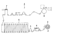
図1は吐出機構(インクジェットヘッドという)を使用した薄膜形成装置の従来例を示す概略図である。図中1は塗布装置を示す。塗布装置1は、ロール状に巻かられた連続した支持体2を巻き出す巻きだし機3と支持体の張力を一定に保つダンサーロール4、支持体の搬送抵抗力を与えるサクションロール5、装置を止めないで支持体を繋ぐ時等に使用するアキュムレータ6、支持体の搬送途中の蛇行を制御する蛇行制御ロール7、バックアップローラ8を有し、バックアップローラ8の上方にはインクジェットヘッド9が一定の間隔を持って配置されている。
FIG. 1 is a schematic view showing a conventional example of a thin film forming apparatus using an ejection mechanism (referred to as an inkjet head). In the figure, 1 indicates a coating apparatus. The coating apparatus 1 includes an
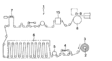
図2は本発明の請求項2に係る薄膜形成装置の一例を示す概略図である。従来例(図1)と異なるところは連続した支持体2がインクジェットヘッド9を通過する前にコロナ放電処理手段15を設けた点である。 FIG. 2 is a schematic view showing an example of a thin film forming apparatus according to claim 2 of the present invention. The difference from the conventional example (FIG. 1) is that the corona discharge treatment means 15 is provided before the continuous support 2 passes through the inkjet head 9.
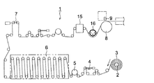
図3は本発明の請求項3に係る薄膜形成装置の一例を示す概略図である。図3では図2に示したコロナ放電処理手段15とインクジェットヘッド9まで、支持体2の表面にロール接触がないように空気により支持体を浮上させた無接触搬送手段16を設けている。
FIG. 3 is a schematic view showing an example of a thin film forming apparatus according to
図4は本発明の請求項6に係る薄膜形成装置の一例を示す概略図である。図4では図3に示す無接触搬送手段16の替わりに支持体2の表面の帯電量を制御する除電バー17と除塵処理を行う除塵処理手段18を設けている。
FIG. 4 is a schematic view showing an example of a thin film forming apparatus according to
図5は本発明の請求項6に係る薄膜形成装置の一例を示す概略図である。図5では図4
に示す除電バー17と除塵処理手段18の替わりに支持体2の表面温度を20〜80℃の範囲内に加温する処理を行う加温手段19を設けている。
FIG. 5 is a schematic view showing an example of a thin film forming apparatus according to
In place of the
図6はインクジェットヘッド9と、塗布液供給部10と、インクジェットヘッドを駆動制御する駆動制御部903を有した溶剤吐出機構を示す。インクジェットヘッド9は同じ種類のヘッドを複数個支持体2の表面幅方向に並べたものであり、支持体2の幅により適宜並べる数を変更することが可能である。又、複数列にして幅方向に並べてもかまわない。あるいはインクジェットヘッド9を、塗布時に移動手段(不図示)により待機部から移動用レールに沿って移動(不図示)し、被塗布物上の塗布するインクジェットヘッド移動型でもかまわない。
FIG. 6 shows a solvent ejection mechanism having an inkjet head 9, a coating
本発明に係るインクジェットヘッドとしては特に限定はなく、例えば発熱素子を有し、この発熱素子からの熱エネルギーによりインクの膜沸騰による急激な体積変化によりノズルからインクを吐出させるサーマルヘッドでも良いし、インク圧力室に圧電素子を備えた振動板を有しており、この振動板によるインク圧力室の圧力変化でインクを吐出させる剪断モード型(ピエゾ型)インクジェットヘッドであっても良い。特に好ましいのは剪断モード型(ピエゾ型)インクジェットヘッドである。 The inkjet head according to the present invention is not particularly limited, and may be, for example, a thermal head that has a heating element and ejects ink from nozzles due to a rapid volume change due to ink film boiling due to thermal energy from the heating element. It may be a shear mode type (piezo type) ink jet head that has a vibration plate provided with a piezoelectric element in the ink pressure chamber and discharges ink by a pressure change of the ink pressure chamber by the vibration plate. Particularly preferred is a shear mode type (piezo type) ink jet head.
本発明ではインクジェットヘッド9が剪断モード型(ピエゾ型)インクジェットヘッドの場合に付き説明している。 In the present invention, the case where the ink jet head 9 is a shear mode type (piezo type) ink jet head is described.
図6で本発明に使用したインクジェットヘッドについて説明する。塗布液供給部10は塗布液貯蔵タンク101と、塗布液貯蔵タンク101内の塗布液102(図6を参照)をインクジェットヘッド9に供給する配管103と、塗布液102の供給量を制御する制御バルブ104と、一部外気と連通させるための配管105とを有している。配管103はインクジェットヘッド9に接合されおり、柔軟性の材料で出来ていることが望ましく、例えばフレキホース、ポリエチレン製ホース、ポリプロピレン製ホース等が挙げられる。
The ink jet head used in the present invention will be described with reference to FIG. The coating
なお、塗布液102は、絶対濾過精度または準絶対濾過精度が0.4〜50μmの濾材を少なくとも1回は通過させることが好ましい。
In addition, it is preferable to pass the
903はインクジェットヘッド9の圧電振動素子91を駆動させるための制御部を示す。制御部903はコネクタ(不図示)を介してインクジェットヘッド9に接続されている。この制御部903により、圧電振動素子91の動作強度や周波数、塗布液吐出時のノズルの選択等が行われる。105は一部外気と連通させるための配管105を示す。また910は溶液貯蔵タンクで溶液911は用途により変更すすることが可能である。例えばインクジェットヘッドを洗浄する場合は洗浄液を、塗布前にインクジェットヘッドに塗布液を充填する場合は塗布液を入れて使用することが可能である。
図7は剪断モード型のインクジェットヘッドの一部破断面を有する概略斜視図である。図中、901d1は塗布液を液滴として吐出するノズル吐出口、901aはインクジェットヘッド9のノズル板901dの表面を示す。901d1のノズル吐出口の間隔は、0.02〜0.3mmが好ましい。
FIG. 7 is a schematic perspective view having a partially broken surface of a shear mode type ink jet head. In the figure, reference numeral 901d1 denotes a nozzle discharge port for discharging the coating liquid as droplets, and 901a denotes the surface of the
以下に本発明の実施例を挙げて具体的に説明するが、本発明の実施態様はこれらの例に限定されるものではない。
<試料の作製>
[塗布液の準備]
ジペンタエリスリトールヘキサアクリレート単量体 60質量部
ジペンタエリスリトールヘキサアクリレート2量体 20質量部
ジペンタエリスリトールヘキサアクリレート3量体以上の成分 20質量部
ジメトキシベンゾフェノン 4質量部
酢酸エチル 45質量部
メチルエチルケトン 45質量部
イソプロピルアルコール 60質量部
[塗布液の調製、支持体の準備]
塗布液粘度 5.2mPa・s(B型粘度計 25℃)
支持体 ポリエチレンテレフタレートフィルム(厚さ75μm幅600mm長さ1000m)
[塗布形成]
図2に示す塗布装置を使用した。バックアップロール上に支持された支持体上にインクジェットヘッドから液滴を射出し塗膜を得た。インクジェットヘッドはせん断モード型(ピエゾ型)であり、ノズル吐出口の径0.04mm、塗布液1滴当たりの平均吐出量50pl、ノズル間のピッチは0.07mm、ノズル数500のものを使用した。インクジェットヘッドは千鳥に配置し550mmの塗布幅が得られるように複数個を配置した。被塗布物である支持体の搬送速度は10m/minとし、着弾時のウェット膜厚が5μmとなるように射出周期を制御した。その後塗膜を設けた支持体を連続的に搬送し、塗布工程の下流側に設けられた乾燥工程で溶媒を乾燥させ乾燥塗膜を得た。乾燥条件は100℃、20秒間とした。塗工部の環境温度は25℃とし、塗布液温度も25℃となるように保温した。
Examples of the present invention will be specifically described below, but the embodiments of the present invention are not limited to these examples.
<Preparation of sample>
[Preparation of coating solution]
Dipentaerythritol hexaacrylate monomer 60 parts by weight Dipentaerythritol hexaacrylate dimer 20 parts by weight Dipentaerythritol hexaacrylate trimer component 20 parts by weight Dimethoxybenzophenone 4 parts by weight Ethyl acetate 45 parts by weight Methyl ethyl ketone 45 parts by weight Isopropyl alcohol 60 parts by mass [Preparation of coating solution, preparation of support]
Coating solution viscosity 5.2 mPa · s (B-type viscometer 25 ° C)
Support Polyethylene terephthalate film (thickness 75μm width 600mm length 1000m)
[Coating formation]
The coating apparatus shown in FIG. 2 was used. Droplets were ejected from an inkjet head onto a support supported on a backup roll to obtain a coating film. The ink jet head is a shear mode type (piezo type), which has a nozzle discharge port diameter of 0.04 mm, an average discharge amount of 50 pl per droplet of coating liquid, a pitch between nozzles of 0.07 mm, and a nozzle number of 500. . A plurality of inkjet heads were arranged in a staggered manner so that a coating width of 550 mm was obtained. The conveyance speed of the support as the coating object was 10 m / min, and the injection cycle was controlled so that the wet film thickness upon landing was 5 μm. Thereafter, the support provided with the coating film was continuously conveyed, and the solvent was dried in a drying process provided on the downstream side of the coating process to obtain a dried coating film. Drying conditions were 100 ° C. and 20 seconds. The environmental temperature of the coating part was 25 ° C., and the temperature of the coating solution was kept at 25 ° C.
[支持体表面の濡れ張力の調整]
支持体の濡れ張力はコロナ処理の電圧および支持体の種類を変化させることにより調整を実施した。
[Adjustment of the wetting tension of the support surface]
The wetting tension of the support was adjusted by changing the voltage of the corona treatment and the type of the support.
[支持体表面の濡れ張力の測定]
春日電機株式会社製濡れ張力試験用混合液を使用して測定を実施した。
[Measurement of wetting tension on support surface]
The measurement was carried out using a mixture for wet tension test manufactured by Kasuga Electric Co., Ltd.
[塗布液の表面張力の調整]
溶剤種類を変えることと界面活性剤量を変化させることにより表面張力の調整する。
[Adjustment of surface tension of coating liquid]
The surface tension is adjusted by changing the solvent type and changing the amount of the surfactant.
[塗布液の表面張力の測定]
ウィルヘルミ(プレート)法を用いた協和界面科学株式会社製表面張力計 CBVP−Zを使用して測定を実施した。
[Measurement of surface tension of coating liquid]
Measurement was performed using a surface tension meter CBVP-Z manufactured by Kyowa Interface Science Co., Ltd. using the Wilhelmi (plate) method.
[塗布膜厚のバラツキ測定]
大塚電子(株)製 光干渉膜厚計 FE−3000を用い、2mm間隔で20cm角の面内膜厚を測定し、最大膜厚と最小膜厚との差を平均膜厚で除した値Aを塗布膜厚のばらつきとした。
[Measurement of coating film thickness variation]
A value obtained by measuring an in-plane film thickness of 20 cm square at intervals of 2 mm using an optical interference film thickness meter FE-3000 manufactured by Otsuka Electronics Co., Ltd., and dividing the difference between the maximum film thickness and the minimum film thickness by the average film thickness A Was defined as the variation in coating film thickness.
<実施例1>
支持体表面濡れ張力と塗布液の表面張力の関係を塗布膜厚ばらつきで表した。
<Example 1>
The relationship between the surface tension of the support surface and the surface tension of the coating solution was expressed by coating film thickness variation.
[塗布膜厚のバラツキの評価ランク]
◎:A≦0.05
○:0.05<A≦0.1
△:0.1<A≦0.5
×:0.5<A
[Evaluation rank of coating film thickness variation]
A: A ≦ 0.05
○: 0.05 <A ≦ 0.1
Δ: 0.1 <A ≦ 0.5
×: 0.5 <A
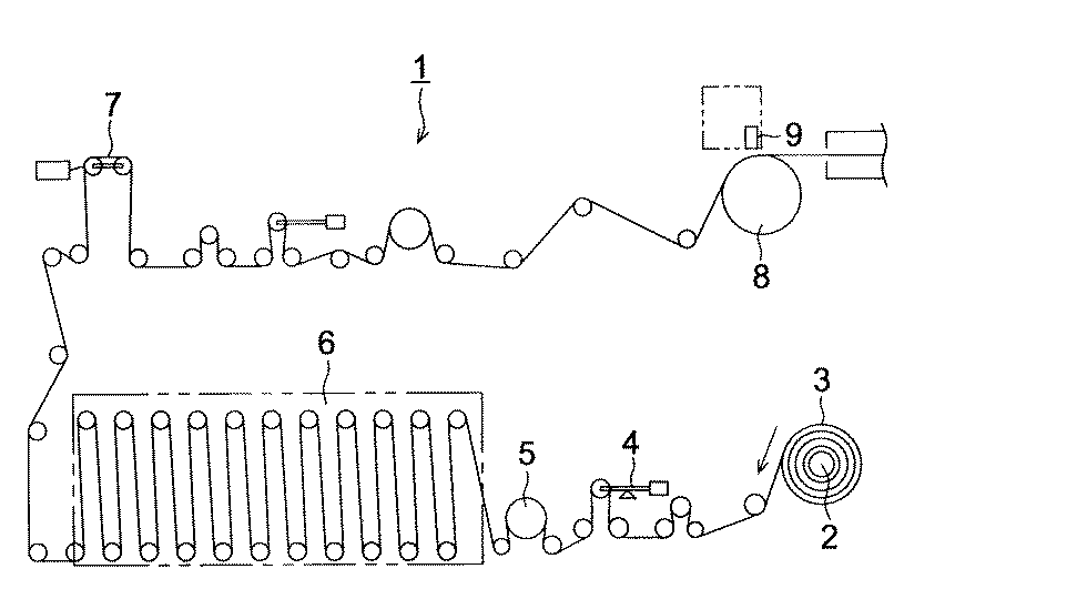
表からわかるように、
1−1 支持体表面濡れ張力が塗布液の表面張力より高い方が塗布膜厚のばらつきは少ない。(試料No.101、115)
1−2 塗布液の表面張力が15dyne/cm〜50dyne/cmのとき塗布膜厚のばらつきは少ない。(試料No.108、115)
1−3 支持体の濡れ張力が30dyne/cm〜70dyne/cmのとき塗布膜厚のばらつきが少ない。(試料No.101、107)
以上1−1、1−2、1−3より、支持体の表面の濡れ張力が30〜70dyne/cmであり、かつ塗布液の表面張力が15〜50dyne/cmであり、支持体の表面濡れ張力は塗布液の表面張力より高いことの3条件が揃ったとき塗布膜厚のばらつきが少ないことが解った。
As you can see from the table,
1-1 When the support surface wet tension is higher than the surface tension of the coating solution, there is less variation in the coating film thickness. (Sample Nos. 101 and 115)
1-2 When the surface tension of the coating solution is 15 dyne / cm to 50 dyne / cm, there is little variation in the coating film thickness. (Sample Nos. 108 and 115)
1-3 When the support has a wetting tension of 30 dyne / cm to 70 dyne / cm, there is little variation in the coating film thickness. (Sample Nos. 101 and 107)
From 1-1, 1-2, and 1-3, the surface tension of the support is 30 to 70 dyne / cm, and the surface tension of the coating solution is 15 to 50 dyne / cm. It was found that the coating film thickness variation was small when the three conditions that the tension was higher than the surface tension of the coating solution were met.
<実施例2>
図2のコロナ処理装置から塗布機までの金属ロールをはずして、替わりに空気を多孔板から噴出して、支持体を接触しないで支持する図3のよう搬送装置を用いて実施例1試料No.105の条件で塗布膜厚のばらつきを評価した。また比較のために図2装置においてのコロナ処理装置から塗布機の間に搬送用ロールを更に3本追加した例を比較として実験評価した。
<Example 2>
Remove the metal roll from the corona treatment device of FIG. 2 to the coating machine, and instead eject air from the perforated plate to support the support without contacting it. . The variation of the coating film thickness was evaluated under 105 conditions. For comparison, an example in which three more transport rolls were added between the corona treatment apparatus and the coating machine in the apparatus of FIG. 2 was experimentally evaluated as a comparison.
表からコロナ放電処理を実施した位置から吐出機構まで、支持体表面にロール接触がないと、塗布膜厚ばらつきはない。 If there is no roll contact on the surface of the support from the position where the corona discharge treatment is performed to the discharge mechanism from the table, there is no coating film thickness variation.
<実施例3>
図4に示すように図3の無接触搬送手段の替わりに支持体2の表面の帯電量を制御する除電バーと除塵処理を行う除塵処理手段を設け、実施例1試料No.105の条件で支持体上の帯電量と塗布膜厚のばらつきの関係を評価した。
<Example 3>
As shown in FIG. 4, in place of the non-contact conveying means of FIG. 3, a charge removal bar for controlling the charge amount on the surface of the support 2 and a dust removal treatment means for carrying out dust removal treatment are provided. The relationship between the amount of charge on the support and the variation in coating film thickness was evaluated under the conditions of 105.
[帯電量の調整]
除電バーと支持体の間隙を変化させることにより、支持体表面上の帯電量を変化させた。
[Adjustment of charge amount]
The amount of charge on the surface of the support was changed by changing the gap between the charge removal bar and the support.
[帯電量の測定]
シシド静電気株式会社製スタチロンDXで、塗布直前の支持体表面での静電気の帯電量を測定した。
[Measurement of charge amount]
The charge amount of static electricity on the surface of the support immediately before coating was measured with a Statiron DX manufactured by SHICIDO static electricity Co., Ltd.
表3より静電気の帯電量は−1kV〜+1kVの範囲内にあるとき塗布膜厚のばらつきが少ない。
さらに試料No.301と同条件で除塵装置((株)伸高製UVUウェブクリーナー)を設置した結果、試料No.401に示すように塗布膜厚のばらつきがなり効果の確認ができた。
According to Table 3, when the electrostatic charge amount is in the range of −1 kV to +1 kV, the coating film thickness variation is small.
Furthermore, sample no. As a result of installing a dust removing device (UVU web cleaner manufactured by Shindaka Co., Ltd.) under the same conditions as in No. 301, sample No. As shown by 401, the coating film thickness varied and the effect could be confirmed.
<実施例4>
図5に示すように図4の除電バーと除塵処理手段の替わりに支持体2の表面温度を20〜80℃の範囲内に加温する処理を行う加温手段を設け、温度と塗布膜厚のばらつきの関係を評価した。
<Example 4>
As shown in FIG. 5, instead of the static elimination bar and the dust removal treatment means shown in FIG. 4, a heating means for performing a treatment for heating the surface temperature of the support 2 within a range of 20 to 80 ° C. is provided. The relationship of variation was evaluated.
[支持体温度の調整]
コロナ放電処理機のあとに、温水を通水できるジャケットロールを設置し、温水の温度を変化させることにより、塗布時の支持体の温度を測定した。
[Adjustment of support temperature]
After the corona discharge treatment machine, a jacket roll capable of passing warm water was installed, and the temperature of the support during coating was measured by changing the temperature of the warm water.
[温度の測定]
支持体の温度は株式会社キーエンス製非接触ハンディ温度計IT2−80により測定した。
[Temperature measurement]
The temperature of the support was measured with a non-contact handy thermometer IT2-80 manufactured by Keyence Corporation.
表4より塗布時の支持体の表面温度は20℃〜80℃のとき塗布膜厚のばらつきが少ない。 From Table 4, the surface temperature of the support during coating is less than 20 ° C. to 80 ° C., and there is little variation in coating film thickness.
<実施例5>
支持体の表面粗さがどのように塗布膜厚に影響を与えるかを、支持体の表面粗さと塗布膜厚の比率の関係で測定評価した。
<Example 5>
How the surface roughness of the support affects the coating thickness was measured and evaluated by the relationship between the surface roughness of the support and the ratio of the coating thickness.
[塗布膜厚の調整]
塗布膜厚は支持体の搬送速度を変化することにより調整した。
[Adjustment of coating thickness]
The coating film thickness was adjusted by changing the conveyance speed of the support.
[支持体の支持体表面荒さRaの調整]
支持体の表面を微細な砥石で磨くことにより、砥石の番手と磨き時間を調整することにより、表面凹凸を調整し、Raを変化させた。
[Adjustment of support surface roughness Ra of support]
By polishing the surface of the support with a fine grindstone, the surface irregularities were adjusted by changing the grindstone count and polishing time, and Ra was changed.
[支持体の支持体表面荒さRaの測定]
支持体の表面凹凸の変形量を キーエンス(株)製 CCDレーザー変位計 LK−G を用いて測定した結果より計算により算出した。
[Measurement of support surface roughness Ra of support]
The amount of deformation of the surface irregularities of the support was calculated from the results of measurement using a CCD laser displacement meter LK-G manufactured by Keyence Corporation.
表より支持体の表面粗さRaが0.01〜10μmであり(試料No.608参照)、塗布膜厚が0.5〜50μmであり(試料No.601、607、615参照)、支持体の表面粗さRaは塗布膜厚の0.1%〜10%である(試料No.621参照)の3条件が揃ったとき塗布膜厚のばらつきが少ないことがわかる。なお表5において試料No.614に示すように上記3条件が上限値、下限値のときは塗布膜厚のばらつきが大きく、NGと判定した。 According to the table, the surface roughness Ra of the support is 0.01 to 10 μm (see sample No. 608), the coating film thickness is 0.5 to 50 μm (see sample Nos. 601, 607, and 615), and the support. The surface roughness Ra is 0.1% to 10% of the coating film thickness (see sample No. 621). In Table 5, sample No. As indicated by 614, when the above three conditions were the upper limit value and the lower limit value, the coating film thickness varied greatly and it was determined as NG.
1 塗布装置
2 支持体
3 巻きだし機
4 ダンサーロール
5 サクションロール
6 アキュムレータ
7 蛇行制御ロール
8 バックアップローラ
9 インクジェットヘッド
10 塗布液供給部
15 コロナ放電処理手段
16 無接触搬送手段
17 除電バー
18 除塵処理手段
19 加温手段
91 圧電振動素子
101 塗布液貯蔵タンク
102 塗布液
903 制御部
910 溶液貯蔵タンク
DESCRIPTION OF SYMBOLS 1 Application | coating apparatus 2
Claims (12)
連続して供給される支持体の表面の濡れ張力が30〜70dyne/cmであり、かつ前記塗布液の表面張力が15〜50dyne/cmであり、前記支持体の表面の濡れ張力は前記塗布液の表面張力より高いことを特徴とする薄膜形成装置。 In a thin film forming apparatus that forms a thin film by applying droplets from a discharge mechanism having a droplet discharge head that discharges a coating liquid in which a film material is dissolved or dispersed in a solvent onto a support.
The wetting tension of the surface of the support that is continuously supplied is 30 to 70 dyne / cm, the surface tension of the coating solution is 15 to 50 dyne / cm, and the wetting tension of the surface of the support is the coating solution. A thin film forming apparatus characterized by being higher than the surface tension of the film.
塗布液を塗布する直前の前記支持体の表面の帯電量が−1kV〜+1kVの範囲内になるように制御する制御手段を有することを特徴とする薄膜形成装置。 A thin film forming apparatus that forms a thin film by applying droplets from a discharge mechanism having a droplet discharge head for discharging a coating liquid in which a film material is dissolved or dispersed in a solvent onto a support. And
A thin film forming apparatus comprising control means for controlling the amount of charge on the surface of the support immediately before applying the coating liquid to be within a range of -1 kV to +1 kV.
連続して供給される前記支持体の表面に均一な除電処置を施した後に、除塵処理を行う除塵処理手段を有することを特徴とする請求項4又は5に記載の薄膜形成装置。 A thin film forming apparatus that forms a thin film by applying droplets from a discharge mechanism having a droplet discharge head for discharging a coating liquid in which a film material is dissolved or dispersed in a solvent onto a support. And
6. The thin film forming apparatus according to claim 4, further comprising dust removal processing means for performing dust removal processing after performing uniform charge removal treatment on the surface of the support that is continuously supplied.
連続して供給される前記支持体の表面温度を20〜80℃の範囲内に加温する処理を行う加温手段を有することを特徴とする薄膜形成装置。 A thin film forming apparatus that forms a thin film by applying droplets from a discharge mechanism having a droplet discharge head for discharging a coating liquid in which a film material is dissolved or dispersed in a solvent onto a support. And
A thin film forming apparatus comprising a heating means for performing a process of heating the surface temperature of the support that is continuously supplied within a range of 20 to 80 ° C.
連続して供給される前記支持体の表面粗さRaが0.01〜10μmであり、塗布膜厚が0.5〜50μmであり、支持体の表面粗さRaは塗布膜厚の0.1%〜10%であることを特徴とする薄膜形成装置。 A thin film forming apparatus that forms a thin film by applying droplets from a discharge mechanism having a droplet discharge head for discharging a coating liquid in which a film material is dissolved or dispersed in a solvent onto a support. And
The surface roughness Ra of the support continuously supplied is 0.01 to 10 μm, the coating film thickness is 0.5 to 50 μm, and the surface roughness Ra of the support is 0.1 of the coating film thickness. The thin film forming apparatus is characterized by being 10% to 10%.
Priority Applications (1)
| Application Number | Priority Date | Filing Date | Title |
|---|---|---|---|
| JP2005108506A JP2006281176A (en) | 2005-04-05 | 2005-04-05 | Thin film forming apparatus |
Applications Claiming Priority (1)
| Application Number | Priority Date | Filing Date | Title |
|---|---|---|---|
| JP2005108506A JP2006281176A (en) | 2005-04-05 | 2005-04-05 | Thin film forming apparatus |
Publications (1)
| Publication Number | Publication Date |
|---|---|
| JP2006281176A true JP2006281176A (en) | 2006-10-19 |
Family
ID=37403628
Family Applications (1)
| Application Number | Title | Priority Date | Filing Date |
|---|---|---|---|
| JP2005108506A Pending JP2006281176A (en) | 2005-04-05 | 2005-04-05 | Thin film forming apparatus |
Country Status (1)
| Country | Link |
|---|---|
| JP (1) | JP2006281176A (en) |
Cited By (4)
| Publication number | Priority date | Publication date | Assignee | Title |
|---|---|---|---|---|
| WO2008149652A1 (en) * | 2007-06-06 | 2008-12-11 | Konica Minolta Opto, Inc. | Coating applicator |
| CN102371230A (en) * | 2011-09-27 | 2012-03-14 | 苗小胜 | Multifunctional non-basecoat coating machine |
| JP2013245027A (en) * | 2012-05-23 | 2013-12-09 | Bellmatic Ltd | Buffer device |
| CN109848003A (en) * | 2019-03-11 | 2019-06-07 | 张溯材 | A kind of optics coating composite production line of adjustable scraping structure |
-
2005
- 2005-04-05 JP JP2005108506A patent/JP2006281176A/en active Pending
Cited By (5)
| Publication number | Priority date | Publication date | Assignee | Title |
|---|---|---|---|---|
| WO2008149652A1 (en) * | 2007-06-06 | 2008-12-11 | Konica Minolta Opto, Inc. | Coating applicator |
| US8882238B2 (en) | 2007-06-06 | 2014-11-11 | Konica Minolta Opto, Inc. | Coating device |
| CN102371230A (en) * | 2011-09-27 | 2012-03-14 | 苗小胜 | Multifunctional non-basecoat coating machine |
| JP2013245027A (en) * | 2012-05-23 | 2013-12-09 | Bellmatic Ltd | Buffer device |
| CN109848003A (en) * | 2019-03-11 | 2019-06-07 | 张溯材 | A kind of optics coating composite production line of adjustable scraping structure |
Similar Documents
| Publication | Publication Date | Title |
|---|---|---|
| US8109595B2 (en) | Droplet ejection apparatus and cleaning method of a droplet receiving surface | |
| US7810897B2 (en) | Droplet ejection apparatus and cleaning method of a droplet receiving surface | |
| US9343339B2 (en) | Coating method and coating apparatus | |
| US8646906B2 (en) | Image recording device and image recording method | |
| US20130021407A1 (en) | Nozzle surface cleaning device and liquid droplet ejecting apparatus | |
| US20120236059A1 (en) | Recording apparatus | |
| JP4852257B2 (en) | Solution coating apparatus and coating method | |
| JPH08250389A (en) | Thin film forming apparatus and thin film forming method | |
| JP4259107B2 (en) | Droplet discharge head cleaning device, droplet discharge head cleaning method, and droplet discharge device | |
| JP2010075813A (en) | Coating method | |
| JP5899424B2 (en) | Coating apparatus and coating method | |
| EP3248798B1 (en) | Recording apparatus and recording method | |
| JPWO2008149652A1 (en) | Coating device | |
| EP3666535B1 (en) | Printing device | |
| JPWO2018186159A1 (en) | Liquid ejection device | |
| JP2019059029A (en) | Nozzle surface wiping device for liquid droplet discharge head and liquid droplet discharge device | |
| JP5442402B2 (en) | Liquid coating method and liquid coating apparatus | |
| JP4920115B2 (en) | Solution coating apparatus and coating method | |
| JP2006082459A (en) | Recording head and ink jet printer using the recording head | |
| JP2008044721A (en) | Droplet discharge device | |
| JP2006326456A (en) | Coating method | |
| JP2002162858A (en) | Release agent supplying system for image forming device | |
| JP2004337799A (en) | Coating apparatus and method for applying coating liquid | |
| JP2024078397A (en) | HEAD MODULE, IMAGE FORMING APPARATUS AND LIQUID EJECTION APPARATUS | |
| JP2021187013A (en) | Image formation apparatus and control method |