JP2006328811A - Construction method of sand discharge facility using temporary drainage channel in dyke - Google Patents
Construction method of sand discharge facility using temporary drainage channel in dyke Download PDFInfo
- Publication number
- JP2006328811A JP2006328811A JP2005154132A JP2005154132A JP2006328811A JP 2006328811 A JP2006328811 A JP 2006328811A JP 2005154132 A JP2005154132 A JP 2005154132A JP 2005154132 A JP2005154132 A JP 2005154132A JP 2006328811 A JP2006328811 A JP 2006328811A
- Authority
- JP
- Japan
- Prior art keywords
- concrete
- dam
- drainage channel
- temporary drainage
- opening
- Prior art date
- Legal status (The legal status is an assumption and is not a legal conclusion. Google has not performed a legal analysis and makes no representation as to the accuracy of the status listed.)
- Granted
Links
Images

Landscapes
- Barrages (AREA)
Abstract
【課題】 ダムの貯水池における堆積物を下流側に放流する排砂設備を比較的低コストで効率良く構築することができる工法を提供する。
【解決手段】 ダム建設時に仮排水路として堤体内に設けられ、ダム建設後はコンクリートが充填されて塞がれている仮排水路からコンクリートを撤去する工程と、コンクリートが充填されている仮排水路の上流側に開口を形成する工程と、上流側開口を形成する工程に先立ち上流側開口周りを囲って作業空間を形成する工程と、コンクリートを撤去したトンネルに堆積物を通過させるための放流通路を形成する工程と、堆積物を含む水の放流量を調整するため放流通路を開閉する手段を設ける工程とを含む。
【選択図】 図1PROBLEM TO BE SOLVED: To provide a construction method capable of efficiently constructing a sand discharge facility for discharging sediment in a reservoir of a dam to the downstream side at a relatively low cost.
SOLUTION: A step of removing concrete from a temporary drainage channel which is provided in a dam body as a temporary drainage channel at the time of dam construction and is filled with concrete after the dam construction, and a temporary drainage which is filled with concrete A step of forming an opening upstream of the road, a step of forming a work space around the upstream opening prior to the step of forming the upstream opening, and a discharge for passing the sediment through the tunnel from which the concrete has been removed. Forming a passage and providing a means for opening and closing the discharge passage in order to adjust the discharge flow rate of the water containing the deposit.
[Selection] Figure 1
Description
本発明は、ダムの貯水池において、低層密度濁流を中心とした排砂を行うことにより堆砂の進行を抑制するための設備の構築工法に関する。 The present invention relates to a construction method for facilities for suppressing the progress of sedimentation by discharging sand centered on low-density turbidity in a reservoir of a dam.
ダムでは、上流から土砂や濁水が貯水池に流入し、水底に泥や土砂などの堆積物が蓄積される。ダムは、このような堆積物の容量を予め計算したうえで、設計されるものであるが、予期せぬ自然環境の変化などの要因により、予想を上回る容量の堆積物が溜まることがある。 In the dam, sediment and muddy water flow into the reservoir from upstream, and sediment such as mud and sediment accumulates on the bottom of the dam. The dam is designed after the capacity of such deposits is calculated in advance. However, due to factors such as unexpected changes in the natural environment, the capacity of sediments may exceed the expected level.
このような堆積物を貯水池から除去する装置としては、例えば、特開平10−118698号公報(特許文献1)に、水底を走行することができるバケットホイール付き水中作業機が記載されている。この装置は、堆積物を流動化し、水と共に底質分離装置に取り込んで、土砂の粒径に応じて分離処理するものである。
また特開2001−20318号公報(特許文献2)には、貯水池に設けたポンプ浚渫船が、水底から連続的に堆積物を吸引する吸引ポンプを有し、送給管を介して振動フルイに送給する装置が記載されている。
Japanese Patent Laid-Open No. 2001-20318 (Patent Document 2) discloses that a pump dredger provided in a reservoir has a suction pump that continuously sucks sediment from the bottom of the water and sends it to a vibrating fluid through a feed pipe. A device for feeding is described.
上記従来の堆積物の除去設備は、堆積物を分離設備に取り込んで汚泥を取り除き、土砂の粒径等により分別するものであり、堆積物を積極的に下流側に放流しようとするものではない。
すなわち、ダムの下流にある河川には、河床低下が生じたり、河口付近に海岸侵食が生じるものもあり、ダムによる泥や土砂などの堰き止めの影響が懸念されるようになっている。したがって、場所によっては、堆積物を積極的に下流側に放流することが要求されている。
The above-mentioned conventional sediment removal equipment takes the sediment into the separation equipment, removes sludge, and sorts it by the particle size of earth and sand, etc., and does not intend to discharge the sediment actively downstream. .
That is, some rivers downstream of the dam have a riverbed drop or coastal erosion near the mouth of the river, and there is concern about the impact of dams such as mud and sediment. Therefore, depending on the location, it is required to positively release the sediment downstream.
以上のような現状を鑑みて本発明の課題は、主に貯水池に流入する低層密度濁流を効率的に排出することにより、貯水池の堆砂の進行を抑制する排砂設備を比較的低コストで効率良く構築することができる工法を提供することにある。 In view of the current situation as described above, the object of the present invention is to provide a sand discharge facility that suppresses the progress of sedimentation in a reservoir at a relatively low cost by efficiently discharging a low-density turbid flow mainly flowing into the reservoir. The object is to provide a construction method that can be constructed efficiently.
上記課題を解決するために、本発明では、ダム建設時に仮排水路として堤体内に設けられ、ダム建設後はコンクリートが充填されて塞がれている仮排水路からコンクリートを撤去する工程と、コンクリートが充填されている仮排水路の上流側に開口を形成する工程と、該上流側開口を形成する工程に先立ち上流側開口周りを囲って作業空間を形成する工程と、該コンクリートを撤去したトンネルに堆積物を通過させるための放流通路を形成する工程と、堆積物を含む水の放流量を調整するため放流通路を開閉する手段を設ける工程と、を含むことを特徴とする既設ダムにおける排砂設備の構築工法が提供される。
本発明では、ダム建設後にコンクリートが充填されて塞がれている仮排水路のコンクリートを撤去することにより、ダム堤体内にトンネルを形成し、このトンネルに放流通路を形成するものであるため、このトンネル内周部分には仮排水路構築時の補強筋が残されており、新たに補強筋を設けるといった煩雑な工程を省略することができて、工期の短縮化が可能になり、建設コストを抑制することができる。また上流側開口周りを囲って作業空間を形成するものであるため、貯水池から排水して水位を低下させなくても、コンクリートが充填されている仮排水路トンネルの上流側に開口を形成することができて、既設ダムの貯水池の供用を継続しながら排砂設備の構築工事を実施することができる。
In order to solve the above problems, in the present invention, the step of removing the concrete from the temporary drainage channel that is provided in the levee body as a temporary drainage channel at the time of dam construction and filled with concrete after the dam construction, The step of forming an opening on the upstream side of the temporary drainage channel filled with concrete, the step of forming a work space surrounding the upstream side opening prior to the step of forming the upstream side opening, and the concrete were removed. In an existing dam, comprising: a step of forming a discharge passage for allowing sediment to pass through the tunnel; and a step of providing means for opening and closing the discharge passage to adjust the discharge flow rate of water containing the deposit. A construction method for sand removal equipment is provided.
In the present invention, by removing the concrete of the temporary drainage channel filled with concrete after the dam construction, the tunnel is formed in the dam dam body, and the discharge passage is formed in this tunnel. Reinforcing bars at the time of constructing the temporary drainage channel are left in the inner periphery of this tunnel, so that complicated steps such as newly installing reinforcing bars can be omitted, construction time can be shortened, construction cost Can be suppressed. In addition, since the work space is formed around the upstream opening, an opening should be formed upstream of the temporary drainage tunnel filled with concrete without draining from the reservoir and lowering the water level. Therefore, construction work of the sand removal facility can be carried out while continuing to use the reservoir of the existing dam.
本発明において、前記作業空間を形成する工程では、堤体上流側の開口形成予定箇所から貯水池水面まで縦に連通する筒状空間を形成すべく、筒状構造体を堤体に沿って形成し、該筒状構造体の内部の水を排水し、該筒状構造体はその内部に貯水池から浸水しないように水密に形成しても良い。このように堤体に沿って縦に連通する筒状構造体を設ければ、資材や工事機材は、ダム堤体の天端に設置した揚重機で吊り込むことにより、比較的容易に搬入することができる。
筒状構造体は、最下部に底版のみ、或いは底版及び側壁を備える函体を設置し、この底版または函体の上に側壁部材または管状体を吊り下ろし、さらに、側壁部材或いは管状体の吊り下ろし工程を繰り返し行って結合することにより構築することができる。側壁部材は、半円弧状またはコ字状に形成された板材により構成し、これを堤体側面に水密に取り付け、内側に筒状空間を形成するものである。
In the present invention, in the step of forming the work space, a cylindrical structure is formed along the dam body so as to form a cylindrical space that communicates vertically from the planned opening formation location on the upstream side of the dam body to the reservoir water surface. The water inside the cylindrical structure may be drained, and the cylindrical structure may be formed watertight so as not to be submerged from the reservoir. If a cylindrical structure that communicates vertically along the bank is provided in this way, materials and construction equipment can be carried in relatively easily by being suspended by a lifting machine installed at the top of the dam bank. be able to.
In the cylindrical structure, a box having only a bottom plate or a bottom plate and a side wall is installed at the bottom, a side wall member or a tubular body is suspended on the bottom plate or the box, and the side wall member or the tubular body is suspended. It can be constructed by repeating the lowering step and bonding. A side wall member is comprised with the board | plate material formed in semicircular arc shape or U-shape, this is attached to the side of a dam body watertight, and forms cylindrical space inside.
本発明において、前記放流通路を形成する工程では、コンクリート撤去後のトンネルの上流側に開口部材を設け、該トンネル内に複数の管体を搬入して管体同士を連結し、該トンネルと複数の管体及び開口部材との隙間にコンクリートを充填することができる。 In the present invention, in the step of forming the discharge passage, an opening member is provided on the upstream side of the tunnel after the concrete is removed, a plurality of pipes are carried into the tunnel, and the pipes are connected to each other. Concrete can be filled in the gap between the tube body and the opening member.
また本発明では、ダム建設のため堤体内に仮排水路として設けたトンネルの使用が終了したら、該仮排水路をコンクリートの充填により塞ぐこと無く、ダム建設後又はダム建設中に該仮排水路の上流側に開口部材を設け、該仮排水路内に複数の管体を搬入して管体同士を連結し、該仮排水路と複数の管体及び開口部材との隙間にコンクリートを充填することを特徴とする排砂設備の構築工法が提供される。
本発明は、ダム建設のため堤体内に仮排水路として設けたトンネルを、仮排水路としての使用後にコンクリートの充填により塞ぐこと無く、排砂設備に転用する施工方法であり、このトンネル内周部分には仮排水路構築時の補強筋が残されており、新たに補強筋を設けるといった煩雑な工程を省略することができて、工期の短縮化が可能になり、建設コストを抑制することができる。またダムの貯水池の供用を開始する前に、排砂設備の構築施工を行うものであるため、上流側開口周りを仮締切で囲う必要が無く、この点においても工期短縮化と建設コスト抑制が可能になる。
Further, in the present invention, when the use of the tunnel provided as a temporary drainage channel in the dam body for the construction of the dam is completed, the temporary drainage channel is not closed after filling the concrete with the concrete without filling the temporary drainage channel. An opening member is provided on the upstream side, a plurality of pipes are carried into the temporary drainage channel, the pipes are connected to each other, and concrete is filled in a gap between the temporary drainage channel, the plurality of pipes, and the opening member. The construction method of the sand discharge facility characterized by this is provided.
The present invention is a construction method in which a tunnel provided as a temporary drainage channel for dam construction is diverted to a sand discharge facility without being filled with concrete after use as a temporary drainage channel. Reinforcing bars at the time of temporary drainage channel construction are left in the part, and complicated processes such as newly installing reinforcing bars can be omitted, the construction period can be shortened, and construction costs can be reduced. Can do. In addition, since the construction of the sand removal facility is performed before the dam reservoir is put into service, there is no need to surround the upstream opening with a temporary deadline, which also shortens the construction period and reduces construction costs. It becomes possible.
請求項1に記載の発明によれば、ダム建設後にコンクリートが充填されている仮排水路から充填コンクリートを撤去することにより、ダム堤体内にトンネルを形成し、このトンネルに放流通路を形成するものであるため、比較的低コストで効率よく、排砂設備を構築することができる。
一般にこれらの仮排水路はダムの比較的低い位置に設置されていることが多く、低層密度濁流を効率よく放流するために適した位置に設置されている。低層密度濁流の貯水池への流入は、洪水時に最も多くなるため、排砂設備を洪水調整時に操作することにより土砂を効果的に下流に放流し、貯水池の堆砂を抑制することができる。
また、これらの操作は、洪水時に上流の土砂が下流に流下する自然河川の機能に近いものを提供する。
According to the invention described in claim 1, by removing the filled concrete from the temporary drainage channel filled with concrete after the dam construction, a tunnel is formed in the dam body, and a discharge passage is formed in the tunnel. Therefore, sand removal equipment can be constructed efficiently at a relatively low cost.
In general, these temporary drainage channels are often installed at a relatively low position of the dam, and are installed at a position suitable for efficiently discharging the low-density turbidity flow. Since the inflow of low-density turbidity into the reservoir is the largest during floods, operating the sand removal facility during flood control effectively discharges sediments downstream and suppresses sedimentation in the reservoir.
In addition, these operations provide a function close to the function of a natural river where sediment from the upstream flows down in the event of a flood.
また請求項4に記載の発明によれば、ダム建設のため仮排水路として設けたトンネルを排砂設備に転用する工事を、ダム貯水池の供用開始前に行うものであるため、より一層の工期短縮化と建設コスト抑制が可能になる。 Further, according to the invention described in claim 4, since the construction for converting the tunnel provided as a temporary drainage channel for the construction of the dam to the sand removal facility is performed before the start of the operation of the dam reservoir, the construction period is further increased. Shortening and construction cost control are possible.
以下、本発明の実施の形態を添付図面に基づいて説明するが、本発明はこれに限定されるものではない。 Hereinafter, embodiments of the present invention will be described with reference to the accompanying drawings, but the present invention is not limited thereto.
<第一の実施形態>
[排砂設備の構築工法の概要]
本発明にかかる排砂設備の構築工法は、既設ダムを建設する際に仮排水路として堤体内に設けられ、ダム建設後はコンクリートが充填されて塞がれている仮排水路から充填コンクリートを撤去し、ここに堆積物を通過させるための放流通路を形成することを特徴とするものであり、主要な工程として、上流側仮締切の設置工程、充填コンクリートの撤去工程、上流側開口の形成工程、放流通路の形成工程、放流通路の開閉手段の設置工程等を含むものであり、さらに、下流バルブ室の構築工程、主放流バルブと副放流バルブの設置工程、下流導水路の構築工程、掃流管等の設置工程も実施される。
<First embodiment>
[Outline of construction method of sand removal equipment]
The construction method of the sand removal facility according to the present invention is provided in the levee body as a temporary drainage channel when constructing an existing dam, and after the dam construction, the filled concrete is removed from the temporary drainage channel that is filled with concrete and blocked. It is characterized by the formation of a discharge passage for removing sediment and allowing the sediment to pass through it. The main steps are the installation process of the upstream temporary deadline, the removal process of the filled concrete, and the formation of the upstream opening. Including a process, a process for forming a discharge passage, a process for installing an opening / closing means for the discharge path, and the like, a process for constructing a downstream valve chamber, a process for installing a main discharge valve and a sub-discharge valve, a process for constructing a downstream water conduit, An installation process such as a sweep pipe is also performed.
[上流側仮締切の設置工程]
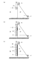
上流側仮締切10は、図1(a)〜(c)に示したように、上流側開口周りを仮締切で囲って作業空間を確保するものであり、ダム堤体11に放流通路の上流側開口を形成する工程に先立ち設置される。
図1(a)に示したように、最初に、クローラクレーン12などの揚重機をダム堤体11の頂部に設置し、このクローラクレーン12によりガイドレール等のガイド部材(図示せず)を吊り下ろし、ガイド部材を潜水作業により堤体上流側面に沿って固定する。次に、ケーソン部材13をクローラクレーン12により吊り下ろし、このケーソン部材13を貯水池14に沈めながら内部に注水し、さらに、ガイド部材に沿って上流側開口付近まで吊り下ろし、ダム堤体11の上流側面に固定する。このケーソン部材13は、仮締切の最下端部を構成するものであり、底版を有し、堤体側面に当接する箇所には側壁が無く、その他の面には側壁を有するものを用いることができる。
他のケーソン部材15も同様にクローラクレーン12により吊り下ろし、順次、最下端のケーソン部材13の上に積み重ねることにより、上流側仮締切10を構築することができる。なお、二段目以降のケーソン部材15は、板材が円弧状断面またはコ字状断面に形成されたものであり、ダム堤体11の側面に当接する箇所に板材を有していないものである。
全ケーソン部材13,15の設置完了後、或いは各ケーソン部材13,15を設置する毎に、ダム堤体11とケーソン部材13,15の側面との隙間を止水材16により塞ぐ。図1(b)に示したように、ケーソン部材13,15の設置完了後、止水性を確認しながら、内部の水を徐々に排水すれば、上流側仮締切10の設置工程が終了する。
上流側仮締切10の下端は、上流側開口の形成作業に支障をきたさないように、上流側開口の形成予定位置よりも若干低く、例えば、上流側開口の下端よりも1m程度低い位置とされる。また上流側仮締切10の上端は、風波浪高による水面変動時にも仮締切内が浸水しないように、貯水池14の運用水位よりも1m程度高い位置とされる。
[Upstream temporary deadline installation process]
As shown in FIGS. 1 (a) to 1 (c), the upstream side
As shown in FIG. 1A, first, a lifting machine such as a
Similarly, the
After the installation of all the
The lower end of the upstream
[充填コンクリートの撤去工程]
仮排水路からコンクリートを撤去する工程では、ダム堤体11に有害な衝撃や振動などを与えないことが必要である。そのため、爆薬を使用せず、膨張材を含む静的破砕剤や機械による掘削が実施される。図示はしないが、機械による掘削方法は、例えば、撤去対象箇所に複数の孔を穿設し、油圧割裂装置等を使用して各孔間のコンクリートを割裂した後に、孔の深さ方向にコンクリートを掘削する。破砕したコンクリートをダム堤体11の下流側に設けた作業構台17まで搬出しながら、以上の工程を繰り返し行う。
なお、コンクリートの掘削作業は、ほとんどがダム堤体11の下流側から行われるものであり、したがって、コンクリートの撤去工程は、図1(a)〜(c)に示したように、上流側仮締切10の設置工程と並行して実施することが可能であり、上流側仮締切10の完成後には、ダム堤体11の上流側への貫通のみを実施することも可能である。
[Removal process of filled concrete]
In the process of removing concrete from the temporary drainage channel, it is necessary not to give a harmful impact or vibration to the
It should be noted that most of the concrete excavation work is performed from the downstream side of the
[上流側開口の形成工程]
ダム堤体の下流側からコンクリート撤去作業を進め、上流側に残された既存コンクリートの厚さが、例えば500mm程度まで薄くなったら、この部分はダム堤体の上流側からの迎え掘りにより撤去することができる。このように上流側開口を形成した後に、上流側に向かって開口が拡径するように拡幅してコンクリートを除去し、この開口部分すなわち呑口部分に、上流側に拡径する開口部材(ベルマウス)やゲート戸当たり部材を設け、このベルマウス周りにコンクリートを充填する。このコンクリート充填作業は、ダム堤体の頂部にコンクリートポンプ車を配置し、ここからベルマウス周りまで延ばした配管を通して高流動性コンクリートを打設する。これ以外にも、呑口部分には、先端ノズルから空気を噴出する空気管、先端ノズルから水を噴出する掃流管、制水ゲート(図示せず、放流通路の開閉手段)、止水板等を取り付ける。これら部材の取り付け作業は、ダム堤体の頂部のクローラクレーンにより資材や機材を上流側仮締切内に吊り込み、この上流側仮締切の内部で行うことができる。
[Upstream side opening formation process]
Proceed with the concrete removal work from the downstream side of the dam body, and when the thickness of the existing concrete left on the upstream side is reduced to, for example, about 500 mm, this part is removed by digging from the upstream side of the dam body. be able to. After the upstream opening is formed in this way, the concrete is removed by widening the opening so that the diameter of the opening increases toward the upstream side. ) And a gate door contact member, and concrete is filled around the bell mouth. In this concrete filling operation, a concrete pump car is disposed at the top of the dam body, and high fluidity concrete is placed through a pipe extending from here to around the bell mouth. In addition to this, an air pipe that ejects air from the tip nozzle, a sweep pipe that ejects water from the tip nozzle, a water control gate (not shown, means for opening and closing the discharge passage), a water stop plate, etc. Install. The attachment of these members can be performed inside the upstream temporary cutoff by suspending materials and equipment in the upstream temporary cutoff by a crawler crane at the top of the dam dam body.
[放流通路の形成工程]
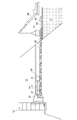
図2に示したように、仮排水路からコンクリートを撤去して形成したトンネル20には、放流管としての鋼管21を設置する。放流管の設置は、外周からの溶接作業が不要な巻き込み鋼管工法により実施するものである。巻き込み鋼管工法は、既知の技術であって、鋼板を鋼管状に巻き込んで縮径し、この縮径状態で固定して設置箇所まで搬送し、設置箇所で拡径して軸方向と周方向に接合する工法である。
すなわち、放流通路を形成するため、コンクリート撤去後のトンネル内20に巻き込み鋼管21の引き込み用及び設置固定用の鋼製架台22を設置する。そして、下流側の作業構台17上にウインチ23を設置し、このウインチ23から索引用ロープ24をトンネル20内に延ばし、上流側開口付近に設けたプーリー25に掛けて折り返し、トンネル20の下流側外部まで延長する。巻き込み鋼管21をクレーン等の揚重機26により鋼製架台22上に設置し、索引用ロープ24に接続してウインチ23で牽引し、巻き込み鋼管21をトンネル20内の上流側から順次、鋼製架台22上の所定位置に設置する。所定位置で巻き込み鋼管21を拡径し、管軸方向に溶接で固定する。この巻き込み鋼管21の鋼製架台22上への設置、牽引、管軸方向の溶接を繰り返し、隣合う鋼管21同士の円周接合部を溶接で固定すると、図3に示した放流管29を形成することができる。
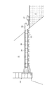
次に、放流管29とトンネル20との隙間に高流動性コンクリートを打設する。このコンクリート打設作業は、作業構台17上にコンクリートポンプ車27を配置し、ここから放流管29とトンネル20との隙間を通して配管28を所定位置まで延ばし、高流動性コンクリートを打設する。
[Formation process of discharge passage]
As shown in FIG. 2, a
That is, in order to form a discharge passage, a
Next, highly fluid concrete is placed in the gap between the
[放流通路の開閉手段の設置工程]
放流通路の開閉手段としては、図4に示したように、呑口部分に設けられた制水ゲート31に加え、放流管29の下流側開口に主ゲート32及び副ゲート33を設置する。
主ゲート32には水圧を引張荷重として受ける構造の引張ラジアルゲートを使用し、土砂の噛み込みが少なく、土砂を多く含んだ濁流も安定して遮断できるものとした。主ゲート32と副ゲート33の上部にはゲートを操作するための開閉装置、油圧装置、操作盤等の機器を設置するためのゲート操作室34を設ける。また引張ラジアルゲートの下流側には、適宜、下流導水路(図示せず)も構築する。呑口部に設ける制水ゲート31には、土砂の堆積、噛み込みによる開閉障害を防止するため、噴流ジェットによりゲート戸当り部の土砂を強制的にフラッシングする掃流装置を設ける。噴流ジェットは貯水池の水を利用して監査廊35に設けた渦巻きポンプ36から配管により制水ゲート31の底面付近へ導く機構である。
なお、引張ラジアルゲートとは、扉体が円弧状に形成されたゲートであって、その円弧の中心を軸として回転して開閉するように、回転軸、軸受、脚が設けられており、さらに、引張ラジアルゲートは水圧が引張荷重として作用するように、回転軸が円弧状扉体よりも上流側に配置されている。また本実施例では、扉体を開閉するためのシリンダーを扉体よりも下方に配置し、開閉シリンダーを伸張したときに扉体が開き、開閉シリンダーを収縮したときに扉体が閉じるように設置する。
[Installation process of opening / closing means for discharge passage]
As a means for opening and closing the discharge passage, as shown in FIG. 4, a
The
The tensile radial gate is a gate whose door body is formed in an arc shape, and is provided with a rotating shaft, a bearing, and a leg so as to open and close by rotating about the center of the arc. In the tension radial gate, the rotation shaft is arranged on the upstream side of the arcuate door so that the water pressure acts as a tensile load. Also, in this embodiment, the cylinder for opening and closing the door body is arranged below the door body so that the door body opens when the opening and closing cylinder is extended, and the door body closes when the opening and closing cylinder contracts To do.
以上、本発明にかかる排砂設備の構築工法では、既設ダムを建設する際に仮排水路として堤体内に設けられ、ダム建設後はコンクリートが充填されて塞がれている仮排水路からコンクリートを撤去し、ここに堆積物を通過させるための放流通路を形成するものであるため、コンクリート撤去後のトンネルには仮排水路構築時の補強筋が残されており、新たに補強筋を設ける煩雑な工程を省くことができ、工期の短縮や、建設コストの抑制が可能になった。また上流側開口周りを囲って作業空間を形成するものであるため、貯水池を使用しながら排砂設備を構築することができる。 As described above, in the construction method of the sand discharge facility according to the present invention, when an existing dam is constructed, it is provided as a temporary drainage channel in the levee body. The tunnel after the removal of concrete is left with reinforcing bars when constructing a temporary drainage channel, and a new reinforcing bar is provided. The complicated process can be omitted, and the construction period can be shortened and the construction cost can be reduced. Moreover, since the work space is formed around the upstream opening, the sand discharge facility can be constructed while using the reservoir.
[堆積物の除去方法]
次に、図4を参照して堆積物の除去方法について説明する。
堆積物の除去作業を実施していないとき、排砂設備における制水ゲート31は閉鎖されており、主ゲート32及び副ゲート33は開かれた状態になっている。なお、副ゲート33は常に開放された状態が維持される。
堆積物の除去作業を開始する際には、その準備として、主ゲート32を閉鎖し、制水ゲート31との間の放流管29内に水を充たす。これは、制水ゲート31を解放したときに、放流管29内に作用する負圧を抑制するためである。放流管29内に十分に充水したら、制水ゲート31を上昇させて開放し、その後に主ゲート32を開く。これにより、貯水池14の底に溜まった堆積物は放流管29を通って下流導水路へ放流される。
堆積物の放流時には、制水ゲート31、主ゲート32及び副ゲート33の全てが開放状態になっているが、堆積物の排出を終了する際には、主ゲート32を閉鎖することにより水流を止める。次に、若干の隙間が残るように制水ゲート31を下降させ、再び主ゲート32を開くと、強い圧力の水流(フラッシング)が生じ、放流管29内に溜まった土砂を洗い流すことができる。土砂が十分に洗浄されたら、主ゲート32を閉鎖して水の流れを止め、フラッシング操作を終了する。このとき、制水ゲート31は下端に若干の隙間が残されており、この下端の戸溝部分には土砂が溜まっているため、掃流装置を操作して噴流ジェットで堆積土砂を強制的に除去する。戸溝の洗浄の後に、制水ゲート31を下降させて完全に閉鎖した後、主ゲート32を開放する。この際、放流管内に若干の土砂が残った場合、制水ゲート31を再び若干の隙間で開放し、強い圧力の水流(フラッシング)によって土砂を洗い流して常時状態に復帰する。
[Method for removing deposits]
Next, the deposit removal method will be described with reference to FIG.
When the sediment removal operation is not performed, the
When starting the deposit removal operation, the
When the sediment is discharged, all of the
<第二の実施形態>
[排砂設備の構築工法の概要]
第二の実施形態は、ダムを建設する際に仮排水路として堤体内に設けられたトンネルを、仮排水路としての使用が終了した後、コンクリート充填による閉鎖を行わず、これを排砂設備に転用する施工方法であり、主要な工程として、上流側開口の形成工程、放流通路の形成工程、放流通路の開閉手段の設置工程等を含むものであり、さらに、下流バルブ室の構築工程、主放流バルブと副放流バルブの設置工程、下流導水路の構築工程、掃流管等の設置工程も実施される。なお、第二の実施形態では図示を省略し、必要に応じて、第一の実施形態を参照して説明する。
<Second Embodiment>
[Outline of construction method of sand removal equipment]
In the second embodiment, the tunnel provided in the levee body as a temporary drainage channel when constructing a dam is not closed by concrete filling after the use as the temporary drainage channel is finished, and this is used as a sand discharge facility. The main method includes a process for forming an upstream opening, a process for forming a discharge passage, a process for installing a means for opening and closing the discharge passage, and a process for constructing a downstream valve chamber, The installation process of the main discharge valve and the secondary discharge valve, the construction process of the downstream conduit, and the installation process of the headpipe etc. are also carried out. In addition, illustration is abbreviate | omitted in 2nd embodiment, and it demonstrates with reference to 1st embodiment as needed.
[上流側開口の形成工程]
ダム建設の際に仮排水路として設けられたトンネルにおいて、仮排水路としての使用が終了したら、ダム堤体の上流側開口部分すなわち呑口部分に、上流側に拡径する開口部材(ベルマウス)やゲート戸当たり部材を設け、このベルマウス周りにコンクリートを充填する。このコンクリート充填作業や、これ以外の空気噴出ノズル、空気管、水噴出ノズル、掃流管、制水ゲート、止水板等の取り付け作業は、第一の実施形態と同様な方法により行う。
[Upstream side opening formation process]
In a tunnel provided as a temporary drainage channel during the construction of a dam, when the use as a temporary drainage channel ends, an opening member (Bellmouth) that expands the diameter upstream to the upstream opening part of the dam body, that is, the mouth part A gate door stop member is provided, and concrete is filled around the bell mouth. This concrete filling work and other work such as air jet nozzle, air pipe, water jet nozzle, scavenging pipe, water control gate, water stop plate, and the like are performed by the same method as in the first embodiment.
上記工程に引き続いて、[放流通路の形成工程]及び[放流通路の開閉手段の設置工程]を実施する。これら工程は第一の実施形態と同様に実施するものであるため、ここでは、さらなる説明は省略する。 Subsequent to the above-described steps, [the discharge passage forming step] and [the discharge passage opening / closing means installation step] are performed. Since these steps are performed in the same manner as in the first embodiment, further explanation is omitted here.
10 上流側仮締切
11 ダム堤体
13 ケーソン部材
14 貯水池
15 ケーソン部材
29 放流管
10
Claims (4)
Priority Applications (1)
| Application Number | Priority Date | Filing Date | Title |
|---|---|---|---|
| JP2005154132A JP4511416B2 (en) | 2005-05-26 | 2005-05-26 | Construction method of sand discharge facility using temporary drainage channel in dyke |
Applications Claiming Priority (1)
| Application Number | Priority Date | Filing Date | Title |
|---|---|---|---|
| JP2005154132A JP4511416B2 (en) | 2005-05-26 | 2005-05-26 | Construction method of sand discharge facility using temporary drainage channel in dyke |
Publications (2)
| Publication Number | Publication Date |
|---|---|
| JP2006328811A true JP2006328811A (en) | 2006-12-07 |
| JP4511416B2 JP4511416B2 (en) | 2010-07-28 |
Family
ID=37550777
Family Applications (1)
| Application Number | Title | Priority Date | Filing Date |
|---|---|---|---|
| JP2005154132A Expired - Fee Related JP4511416B2 (en) | 2005-05-26 | 2005-05-26 | Construction method of sand discharge facility using temporary drainage channel in dyke |
Country Status (1)
| Country | Link |
|---|---|
| JP (1) | JP4511416B2 (en) |
Cited By (9)
| Publication number | Priority date | Publication date | Assignee | Title |
|---|---|---|---|---|
| JP2013159548A (en) * | 2012-02-09 | 2013-08-19 | Takenaka Doboku Co Ltd | Concrete for scour tunnel, and method of constructing scour bypass tunnel structure using concrete for scour tunnel |
| JP2016156130A (en) * | 2015-02-23 | 2016-09-01 | 三菱日立パワーシステムズ株式会社 | Seal pit for drainage |
| CN107012836A (en) * | 2017-04-21 | 2017-08-04 | 中国科学院、水利部成都山地灾害与环境研究所 | Sill may and levee system |
| CN109469028A (en) * | 2018-12-25 | 2019-03-15 | 中国电建集团贵阳勘测设计研究院有限公司 | A kind of sand removal device for dam gate system |
| CN110258457A (en) * | 2019-06-26 | 2019-09-20 | 中国电建集团成都勘测设计研究院有限公司 | The full hole section maintenance checkdam structure of Canyon Area hydroelectric project diversion tunnel |
| CN113322905A (en) * | 2021-06-04 | 2021-08-31 | 魏红梅 | Waterproof drainage device of hydraulic engineering construction |
| CN114150613A (en) * | 2021-12-09 | 2022-03-08 | 中核华辰建筑工程有限公司 | Temporary drainage construction process for construction of crossing pool body of river channel with large pipe diameter |
| CN114790714A (en) * | 2022-04-24 | 2022-07-26 | 中国电建集团北京勘测设计研究院有限公司 | Later-stage diversion flood-fighting method for closed reservoir basin construction without permanent water release structure |
| CN116145610A (en) * | 2023-02-14 | 2023-05-23 | 中国电建集团贵阳勘测设计研究院有限公司 | A method for ecological demolition and ecological restoration of sedimentation reservoirs |
Citations (4)
| Publication number | Priority date | Publication date | Assignee | Title |
|---|---|---|---|---|
| JPH0544341A (en) * | 1991-08-14 | 1993-02-23 | Taisei Corp | Method of forming and closing upper and lower through holes in slab |
| JPH0925620A (en) * | 1995-07-12 | 1997-01-28 | Penta Ocean Constr Co Ltd | Temporary cutoff method and temporary cutoff box in deep water |
| JPH1060871A (en) * | 1996-08-21 | 1998-03-03 | Koken Boring Mach Co Ltd | Dam renewal method |
| JPH1193147A (en) * | 1997-09-19 | 1999-04-06 | Mitsubishi Heavy Ind Ltd | Sand discharge system |
-
2005
- 2005-05-26 JP JP2005154132A patent/JP4511416B2/en not_active Expired - Fee Related
Patent Citations (4)
| Publication number | Priority date | Publication date | Assignee | Title |
|---|---|---|---|---|
| JPH0544341A (en) * | 1991-08-14 | 1993-02-23 | Taisei Corp | Method of forming and closing upper and lower through holes in slab |
| JPH0925620A (en) * | 1995-07-12 | 1997-01-28 | Penta Ocean Constr Co Ltd | Temporary cutoff method and temporary cutoff box in deep water |
| JPH1060871A (en) * | 1996-08-21 | 1998-03-03 | Koken Boring Mach Co Ltd | Dam renewal method |
| JPH1193147A (en) * | 1997-09-19 | 1999-04-06 | Mitsubishi Heavy Ind Ltd | Sand discharge system |
Cited By (13)
| Publication number | Priority date | Publication date | Assignee | Title |
|---|---|---|---|---|
| JP2013159548A (en) * | 2012-02-09 | 2013-08-19 | Takenaka Doboku Co Ltd | Concrete for scour tunnel, and method of constructing scour bypass tunnel structure using concrete for scour tunnel |
| JP2016156130A (en) * | 2015-02-23 | 2016-09-01 | 三菱日立パワーシステムズ株式会社 | Seal pit for drainage |
| CN107012836A (en) * | 2017-04-21 | 2017-08-04 | 中国科学院、水利部成都山地灾害与环境研究所 | Sill may and levee system |
| CN109469028B (en) * | 2018-12-25 | 2023-10-27 | 中国电建集团贵阳勘测设计研究院有限公司 | A kind of sand discharge device for dam gate system |
| CN109469028A (en) * | 2018-12-25 | 2019-03-15 | 中国电建集团贵阳勘测设计研究院有限公司 | A kind of sand removal device for dam gate system |
| CN110258457A (en) * | 2019-06-26 | 2019-09-20 | 中国电建集团成都勘测设计研究院有限公司 | The full hole section maintenance checkdam structure of Canyon Area hydroelectric project diversion tunnel |
| CN110258457B (en) * | 2019-06-26 | 2024-02-13 | 中国电建集团成都勘测设计研究院有限公司 | Dam structure for overhauling full hole section of diversion tunnel of hydroelectric engineering in canyon area |
| CN113322905A (en) * | 2021-06-04 | 2021-08-31 | 魏红梅 | Waterproof drainage device of hydraulic engineering construction |
| CN113322905B (en) * | 2021-06-04 | 2024-01-23 | 魏红梅 | Waterproof drainage device for hydraulic engineering construction |
| CN114150613A (en) * | 2021-12-09 | 2022-03-08 | 中核华辰建筑工程有限公司 | Temporary drainage construction process for construction of crossing pool body of river channel with large pipe diameter |
| CN114790714A (en) * | 2022-04-24 | 2022-07-26 | 中国电建集团北京勘测设计研究院有限公司 | Later-stage diversion flood-fighting method for closed reservoir basin construction without permanent water release structure |
| CN116145610A (en) * | 2023-02-14 | 2023-05-23 | 中国电建集团贵阳勘测设计研究院有限公司 | A method for ecological demolition and ecological restoration of sedimentation reservoirs |
| CN116145610B (en) * | 2023-02-14 | 2024-05-31 | 中国电建集团贵阳勘测设计研究院有限公司 | A method for ecological removal and ecological restoration of a silt-accumulated reservoir |
Also Published As
| Publication number | Publication date |
|---|---|
| JP4511416B2 (en) | 2010-07-28 |
Similar Documents
| Publication | Publication Date | Title |
|---|---|---|
| KR100880439B1 (en) | Slime removal device and method of cast-in-place pile drilling machine | |
| JP4511416B2 (en) | Construction method of sand discharge facility using temporary drainage channel in dyke | |
| CN113356190B (en) | Pile forming method for cast-in-place pile in karst development area | |
| CN109083177B (en) | Precipitation process of integrated directional vacuum well point pipe | |
| CN110439048B (en) | A hydraulic flushing, excavation and suction device and method for internal support foundation pit engineering | |
| CN108708385B (en) | Integrated directional vacuum well point pipe | |
| JP6870969B2 (en) | How to extubate an existing well | |
| JP4648998B2 (en) | Earth disposal equipment | |
| CN112412368A (en) | A device and method for cleaning slag at the bottom of holes based on reverse circulation of cavitation effect | |
| CN214940580U (en) | Dredger fill-out screening barge platform | |
| CN114606964B (en) | Foundation pit dewatering method used under complex geological conditions | |
| JP2025091421A (en) | Power generation system and power generation method | |
| JP4173932B2 (en) | Bottom sediment discharge method | |
| CN111764417A (en) | Construction method for dismantling riverbank cofferdam structure | |
| JP2024009746A (en) | River improvement methods and river structures | |
| JP5850423B2 (en) | Drilling / turbid water recovery device and treatment method | |
| JP4845537B2 (en) | Pile driving method for underwater structures | |
| CN113802540B (en) | A hydraulic cross-wedge type internal drainage channel cutter for muddy soil with a filter tube | |
| CN219115685U (en) | Permanently-combined seepage-proof structure of dry dock | |
| JP6514975B2 (en) | Waterway construction method | |
| CN114319372B (en) | Construction method of anchorage supporting structure | |
| CN119843707B (en) | Structure and method for combining blocking and drainage of waste slag field in arid region | |
| EP4692459A1 (en) | Building element and method for dealing with silting of water intakes | |
| JP7212660B2 (en) | Coastal structures that reduce sedimentation and erosion caused by coastal sand transport | |
| KR100494355B1 (en) | Structure of Preventing Water Stream Tunnel of Underwater Fabric |
Legal Events
| Date | Code | Title | Description |
|---|---|---|---|
| A621 | Written request for application examination |
Free format text: JAPANESE INTERMEDIATE CODE: A621 Effective date: 20080418 |
|
| A711 | Notification of change in applicant |
Free format text: JAPANESE INTERMEDIATE CODE: A711 Effective date: 20080418 |
|
| A521 | Request for written amendment filed |
Free format text: JAPANESE INTERMEDIATE CODE: A821 Effective date: 20080418 |
|
| A977 | Report on retrieval |
Free format text: JAPANESE INTERMEDIATE CODE: A971007 Effective date: 20091221 |
|
| A131 | Notification of reasons for refusal |
Free format text: JAPANESE INTERMEDIATE CODE: A131 Effective date: 20100105 |
|
| A711 | Notification of change in applicant |
Free format text: JAPANESE INTERMEDIATE CODE: A712 Effective date: 20091218 |
|
| A521 | Request for written amendment filed |
Free format text: JAPANESE INTERMEDIATE CODE: A523 Effective date: 20100304 |
|
| RD03 | Notification of appointment of power of attorney |
Free format text: JAPANESE INTERMEDIATE CODE: A7423 Effective date: 20100304 |
|
| A521 | Request for written amendment filed |
Free format text: JAPANESE INTERMEDIATE CODE: A821 Effective date: 20100304 |
|
| TRDD | Decision of grant or rejection written | ||
| A01 | Written decision to grant a patent or to grant a registration (utility model) |
Free format text: JAPANESE INTERMEDIATE CODE: A01 Effective date: 20100413 |
|
| A01 | Written decision to grant a patent or to grant a registration (utility model) |
Free format text: JAPANESE INTERMEDIATE CODE: A01 |
|
| A61 | First payment of annual fees (during grant procedure) |
Free format text: JAPANESE INTERMEDIATE CODE: A61 Effective date: 20100506 |
|
| FPAY | Renewal fee payment (event date is renewal date of database) |
Free format text: PAYMENT UNTIL: 20130514 Year of fee payment: 3 |
|
| R150 | Certificate of patent or registration of utility model |
Free format text: JAPANESE INTERMEDIATE CODE: R150 Ref document number: 4511416 Country of ref document: JP |
|
| S531 | Written request for registration of change of domicile |
Free format text: JAPANESE INTERMEDIATE CODE: R313531 |
|
| S533 | Written request for registration of change of name |
Free format text: JAPANESE INTERMEDIATE CODE: R313533 |
|
| FPAY | Renewal fee payment (event date is renewal date of database) |
Free format text: PAYMENT UNTIL: 20130514 Year of fee payment: 3 |
|
| R350 | Written notification of registration of transfer |
Free format text: JAPANESE INTERMEDIATE CODE: R350 |
|
| R250 | Receipt of annual fees |
Free format text: JAPANESE INTERMEDIATE CODE: R250 |
|
| S531 | Written request for registration of change of domicile |
Free format text: JAPANESE INTERMEDIATE CODE: R313532 |
|
| R350 | Written notification of registration of transfer |
Free format text: JAPANESE INTERMEDIATE CODE: R350 |
|
| R250 | Receipt of annual fees |
Free format text: JAPANESE INTERMEDIATE CODE: R250 |
|
| R250 | Receipt of annual fees |
Free format text: JAPANESE INTERMEDIATE CODE: R250 |
|
| S531 | Written request for registration of change of domicile |
Free format text: JAPANESE INTERMEDIATE CODE: R313531 |
|
| R250 | Receipt of annual fees |
Free format text: JAPANESE INTERMEDIATE CODE: R250 |
|
| R350 | Written notification of registration of transfer |
Free format text: JAPANESE INTERMEDIATE CODE: R350 |
|
| S111 | Request for change of ownership or part of ownership |
Free format text: JAPANESE INTERMEDIATE CODE: R313117 |
|
| R350 | Written notification of registration of transfer |
Free format text: JAPANESE INTERMEDIATE CODE: R350 |
|
| R250 | Receipt of annual fees |
Free format text: JAPANESE INTERMEDIATE CODE: R250 |
|
| R250 | Receipt of annual fees |
Free format text: JAPANESE INTERMEDIATE CODE: R250 |
|
| R250 | Receipt of annual fees |
Free format text: JAPANESE INTERMEDIATE CODE: R250 |
|
| R250 | Receipt of annual fees |
Free format text: JAPANESE INTERMEDIATE CODE: R250 |
|
| R250 | Receipt of annual fees |
Free format text: JAPANESE INTERMEDIATE CODE: R250 |
|
| S111 | Request for change of ownership or part of ownership |
Free format text: JAPANESE INTERMEDIATE CODE: R313115 |
|
| R350 | Written notification of registration of transfer |
Free format text: JAPANESE INTERMEDIATE CODE: R350 |
|
| R250 | Receipt of annual fees |
Free format text: JAPANESE INTERMEDIATE CODE: R250 |
|
| LAPS | Cancellation because of no payment of annual fees |