JP2006341602A - 被加工物に溝を形成する方法及び装置 - Google Patents
被加工物に溝を形成する方法及び装置 Download PDFInfo
- Publication number
- JP2006341602A JP2006341602A JP2006147599A JP2006147599A JP2006341602A JP 2006341602 A JP2006341602 A JP 2006341602A JP 2006147599 A JP2006147599 A JP 2006147599A JP 2006147599 A JP2006147599 A JP 2006147599A JP 2006341602 A JP2006341602 A JP 2006341602A
- Authority
- JP
- Japan
- Prior art keywords
- saw blade
- workpiece
- output shaft
- stop surface
- workpieces
- Prior art date
- Legal status (The legal status is an assumption and is not a legal conclusion. Google has not performed a legal analysis and makes no representation as to the accuracy of the status listed.)
- Granted
Links
- 238000000034 method Methods 0.000 title claims abstract description 22
- 238000005520 cutting process Methods 0.000 claims abstract description 12
- 239000000853 adhesive Substances 0.000 claims description 7
- 230000001070 adhesive effect Effects 0.000 claims description 7
- 239000002184 metal Substances 0.000 claims description 6
- 239000011248 coating agent Substances 0.000 claims description 2
- 238000000576 coating method Methods 0.000 claims description 2
- 230000008878 coupling Effects 0.000 abstract 1
- 238000010168 coupling process Methods 0.000 abstract 1
- 238000005859 coupling reaction Methods 0.000 abstract 1
- 230000009471 action Effects 0.000 description 2
- 235000015895 biscuits Nutrition 0.000 description 2
- 230000006872 improvement Effects 0.000 description 2
- 239000002023 wood Substances 0.000 description 2
- 230000008859 change Effects 0.000 description 1
- 230000000694 effects Effects 0.000 description 1
- 230000002045 lasting effect Effects 0.000 description 1
- 239000003550 marker Substances 0.000 description 1
- 230000002085 persistent effect Effects 0.000 description 1
- 238000005498 polishing Methods 0.000 description 1
- 230000008569 process Effects 0.000 description 1
Images

Classifications
-
- B—PERFORMING OPERATIONS; TRANSPORTING
- B27—WORKING OR PRESERVING WOOD OR SIMILAR MATERIAL; NAILING OR STAPLING MACHINES IN GENERAL
- B27F—DOVETAILED WORK; TENONS; SLOTTING MACHINES FOR WOOD OR SIMILAR MATERIAL; NAILING OR STAPLING MACHINES
- B27F5/00—Slotted or mortised work
- B27F5/02—Slotting or mortising machines tools therefor
- B27F5/023—Portable plate joiners
-
- B—PERFORMING OPERATIONS; TRANSPORTING
- B27—WORKING OR PRESERVING WOOD OR SIMILAR MATERIAL; NAILING OR STAPLING MACHINES IN GENERAL
- B27B—SAWS FOR WOOD OR SIMILAR MATERIAL; COMPONENTS OR ACCESSORIES THEREFOR
- B27B19/00—Other reciprocating saws with power drive; Fret-saws
- B27B19/006—Other reciprocating saws with power drive; Fret-saws with oscillating saw blades; Hand saws with oscillating saw blades
Landscapes
- Life Sciences & Earth Sciences (AREA)
- Engineering & Computer Science (AREA)
- Mechanical Engineering (AREA)
- Wood Science & Technology (AREA)
- Forests & Forestry (AREA)
- Sawing (AREA)
- Dovetailed Work, And Nailing Machines And Stapling Machines For Wood (AREA)
- Electrical Discharge Machining, Electrochemical Machining, And Combined Machining (AREA)
- Forging (AREA)
- Load-Bearing And Curtain Walls (AREA)
- Processing Of Stones Or Stones Resemblance Materials (AREA)
Abstract
【解決手段】 被加工物に溝を形成する方法及び装置において、振動ドライブ(12)が設けられ、その出力軸上にのこ刃(14)が一方の端部により収容され、のこ刃の他方の端部(16)には切削縁部(17)が設けられる。振動ドライブ(12)は、被加工物の表面とのこ刃(14)との間に特定の角度を持たせて、被加工物に位置付けられ、のこ刃(14)が振動する様式で駆動され、出力軸に対して半径方向に延びる方向に案内部(72)に沿って移動される。このようにして、連結要素は、2つの被加工物が適合するようにこれら2つの被加工物に形成された溝に挿入され、被加工物間に持続的で正確な連結を形成するために、2つの被加工物に接着接合することができる。
【選択図】図1
Description
出力軸にのこ刃が一方の端部により収容され、のこ刃の他方の端部には切削縁が設けられてなる振動ドライブを設ける工程と、
被加工物の表面とのこ刃との間に特定の角度を持たせて、被加工物に振動ドライブを位置付ける工程と、
のこ刃を振動させながら駆動する工程と、
出力軸に対して半径方向に延びる方向に案内部に沿ってのこ刃を案内する工程とを含む。
このような方法により、複数の被加工物に互いに位置合わせされた溝を形成する工程と、
各場合において2つの関連する溝内に連結要素を挿入する工程と、
各連結要素を接着接合することにより、これら被加工物を合わせて結合する工程とを含む。
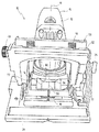
12 振動ドライブ
13 取付台
14 のこ刃
15 ハウジング
16 端部
17 切削縁部
18 基部本体
19 主方向
20 ロッド
22 ばね要素
24 停止面
26 停止面
28 板
30 弓形部
32 溝
34 調整ねじ
36 ピボット軸
37 台板
38 停止面
39 ブロック
42 両矢印
46 歯状ラック
48 調整ねじ
50 フランジ
52 フレーム
54 出力軸
56 長手軸
60 端部
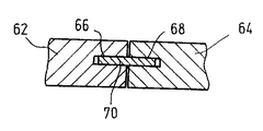
62 被加工物
64 被加工物
66 溝
68 溝
70 連結要素
72 案内部
74 標識
Claims (10)
- 被加工物(62,64)に溝(66,68)を形成する方法であって、
出力軸(54)にのこ刃(14)が第1の端部(60)により収容され、のこ刃の他方の端部(16)には切削縁部(17)が設けられてなる振動ドライブ(12)を設ける工程と、
被加工物の表面とのこ刃(14)との間に特定の角度を持たせて、被加工物(62、64)に振動ドライブ(12)を位置付ける工程と、
のこ刃(14)を振動させながら駆動する工程と、
出力軸(54)に対して半径方向に延びる方向に案内部(72)に沿ってのこ刃(14)を案内する工程とを含む方法。 - のこ刃(14)は、出力軸(54)の長手軸(56)周りに往復振動するように駆動される請求項1に記載の方法。
- のこ刃(14)は、切削縁部(17)が少なくとも特定の箇所で直線状であるように形成されたものを用いる請求項1又は2に記載の方法。
- のこ刃(14)は、1分あたり5000〜30000の振動の頻度で、好ましくは、0.5°〜7°の旋回角で駆動される先行する請求項1〜3のいずれかに記載の方法。
- 少なくとも2つの被加工物を連結する方法であって、
先行する請求項のいずれかに記載の方法により、被加工物(62、64)に互いに位置合わせされた溝(66、68)を形成する工程と、
各場合において2つの関連する溝(66、68)内に連結要素(70)を挿入する工程と、
各連結要素(70)を接着接合することにより、被加工物(62、64)を合わせて結合する工程とを含む方法。 - 金属要素が、木工用接着剤で貼り付け可能とする表面被膜を有して設けられる連結要素(70)として用いられる請求項5に記載の方法。
- 被加工物に溝を形成する装置であって、振動ドライブ(12)を備え、その出力軸(54)にのこ刃(14)が第1の端部(60)により収容され、のこ刃の第2の端部に切削縁部(17)が設けられており、
被加工物の表面に対して特定の角度でのこ刃(14)を位置付けるための少なくとも1つの停止面(24、26、38)と、
出力軸(54)に対して半径方向に延びる方向にのこ刃(14)を移動させるための案内部(72)とをさらに備える装置。 - 被加工物の表面を支持する第1の停止面(24)と、のこ刃(14)により画定される平面からの距離が調整可能とされる第2の停止面(26)とを備える請求項7に記載の装置。
- 第2の停止面(26)は、第1の停止面(24)に対する角度について調整可能である請求項8に記載の装置。
- 出力軸(54)のラジアル平面に平行して延びる第3の停止面(38)を備える請求項8又は9に記載の装置。
Applications Claiming Priority (1)
| Application Number | Priority Date | Filing Date | Title |
|---|---|---|---|
| DE102005027195A DE102005027195A1 (de) | 2005-06-06 | 2005-06-06 | Verfahren und Vorrichtung zum Herstellen von Schlitzen in Werkstücken |
Publications (2)
| Publication Number | Publication Date |
|---|---|
| JP2006341602A true JP2006341602A (ja) | 2006-12-21 |
| JP4550771B2 JP4550771B2 (ja) | 2010-09-22 |
Family
ID=37068984
Family Applications (1)
| Application Number | Title | Priority Date | Filing Date |
|---|---|---|---|
| JP2006147599A Expired - Fee Related JP4550771B2 (ja) | 2005-06-06 | 2006-05-29 | 被加工物に溝を形成する方法及び装置 |
Country Status (8)
| Country | Link |
|---|---|
| US (1) | US7743804B2 (ja) |
| EP (1) | EP1731274B1 (ja) |
| JP (1) | JP4550771B2 (ja) |
| CN (1) | CN100528496C (ja) |
| AT (1) | ATE382455T1 (ja) |
| DE (2) | DE102005027195A1 (ja) |
| ES (1) | ES2297786T3 (ja) |
| PL (1) | PL1731274T3 (ja) |
Families Citing this family (6)
| Publication number | Priority date | Publication date | Assignee | Title |
|---|---|---|---|---|
| DE202006014895U1 (de) * | 2006-09-15 | 2006-11-30 | C. & E. Fein Gmbh | Vorrichtung zur Führung eines Sägeblattes |
| US20100255769A1 (en) * | 2009-04-01 | 2010-10-07 | Farr William E | Roof vent |
| CN101850568A (zh) * | 2010-04-13 | 2010-10-06 | 广州弘亚机械有限公司 | 一种开槽设备 |
| DE102012105520A1 (de) * | 2012-06-25 | 2014-04-24 | C. & E. Fein Gmbh | Tiefenanschlag für oszillierendes Werkzeug |
| US10252441B2 (en) | 2013-08-28 | 2019-04-09 | Corning Incorporated | System and method for cutting a wet green ceramic article |
| CN114603662B (zh) * | 2022-04-26 | 2022-09-23 | 丰县泰宏全屋定制有限公司 | 一种木制楼梯自动化生产用立柱拉槽装置 |
Citations (5)
| Publication number | Priority date | Publication date | Assignee | Title |
|---|---|---|---|---|
| JPH0626801B2 (ja) * | 1989-02-17 | 1994-04-13 | リョービ株式会社 | ビスケットジョインターにおけるフェンス位置調整機構 |
| JPH0747506A (ja) * | 1993-04-27 | 1995-02-21 | Ryobi Motor Prod Corp | 溝切り用プレートジョイナ、及びこれに用いられる調整自在フェンス |
| JPH11179704A (ja) * | 1997-12-25 | 1999-07-06 | Hitachi Koki Co Ltd | 継手用溝掘り機 |
| DE19938106C1 (de) * | 1999-08-12 | 2001-04-26 | C & E Fein Gmbh & Co Kg | Motorgetriebenes Handwerkzeug mit Anschlag |
| DE10250096A1 (de) * | 2002-10-27 | 2004-05-06 | Bruno Gruber | Verfahren zum Verbinden von Bauteilen, Verbindungsteil und Verbundteil |
Family Cites Families (25)
| Publication number | Priority date | Publication date | Assignee | Title |
|---|---|---|---|---|
| US3943934A (en) * | 1974-09-30 | 1976-03-16 | Minnesota Mining And Manufacturing Company | Quick release mechanism for surgical devices |
| US4858663A (en) * | 1988-06-03 | 1989-08-22 | Porter-Cable Corporation | Plate joiner having a quiet drive |
| US4858662A (en) * | 1988-06-03 | 1989-08-22 | Porter-Cable Corporation | Plate joiner having a superior miter guide for mitered carcase joints |
| US4971122A (en) * | 1989-02-17 | 1990-11-20 | Ryobi Ltd. | Fence and fence position adjusting mechanism in joint machine |
| US4913204A (en) * | 1989-09-28 | 1990-04-03 | Black & Decker Inc. | Power biscuit jointer cutter |
| DE4036904C1 (en) * | 1990-11-20 | 1992-05-27 | Aesculap Ag, 7200 Tuttlingen, De | Osteotomy saw with oscillating blade retainer - which is free deposition surface, with blade locking pin compressible under deposition surface |
| DE4135573A1 (de) * | 1990-11-28 | 1992-06-04 | Fein C & E | Verfahren und vorrichtung zum einbringen von oberflaechenkanaelen in plattenmaterial aus weichem werkstoff und verwendung einer vorrichtung |
| JP2533681Y2 (ja) * | 1991-10-21 | 1997-04-23 | 株式会社マキタ | 継手用溝掘り機 |
| US5257654A (en) * | 1992-05-22 | 1993-11-02 | Black & Decker Inc. | Biscuit joiner with retractable antiskid pins |
| DE4336620C2 (de) * | 1993-10-27 | 1997-07-03 | Fein C & E | Elektrowerkzeug mit einer nur bei ausgeschaltetem Motor betätigbaren Spannvorrichtung |
| JPH11512624A (ja) * | 1995-09-18 | 1999-11-02 | イグザクテック,インコーポレーテッド | カウンタバランス揺動式手術用鋸 |
| US5706874A (en) * | 1997-02-03 | 1998-01-13 | Ryobi North America | Biscuit joiner |
| JPH10225910A (ja) * | 1997-02-14 | 1998-08-25 | Ryobi Ltd | 溝加工機 |
| ES2131422T3 (es) * | 1997-04-22 | 1999-07-16 | Lamello Ag | Util para fresar ranuras de lamina. |
| US6896016B1 (en) * | 1997-06-09 | 2005-05-24 | Porter-Cable Corporation | Plate joiner |
| US6336483B1 (en) * | 1997-06-09 | 2002-01-08 | Porter-Cable Corporation | Plate joiner fence angle adjustment system |
| US6125896A (en) * | 1997-06-09 | 2000-10-03 | Porter-Cable Corporation | Plate joiner cutter travel adjustment system |
| US6006802A (en) * | 1997-06-09 | 1999-12-28 | Porter-Cable Corporation | Plate joiner fence height adjustment |
| US5865230A (en) * | 1997-06-09 | 1999-02-02 | Porter-Cable Corporation | Plate joiner |
| US5916221A (en) * | 1997-09-17 | 1999-06-29 | Bristol-Myers Squibb Company | Notch/chamfer guide |
| JP2000005049A (ja) | 1998-06-19 | 2000-01-11 | Tetsuya Maekawa | 省エネ鍋 |
| DE19830096C2 (de) * | 1998-07-06 | 2001-01-25 | Vogel Andreas | Leicht handhabbare Fräsmaschine zur Beseitigung von Kantenbeschädigungen |
| US6260591B1 (en) * | 1999-08-11 | 2001-07-17 | Black & Decker Inc. | Biscuit joiner |
| DE29915578U1 (de) * | 1999-09-04 | 2000-05-31 | Hamann, Rainer, 68519 Viernheim | Schlaufen-Schneide Instrument mit Tiefenanschlag und Führungsfläche |
| DE20209002U1 (de) * | 2002-02-12 | 2002-09-26 | Weiß, Günther, 92706 Luhe-Wildenau | Dübellochfräsmaschine |
-
2005
- 2005-06-06 DE DE102005027195A patent/DE102005027195A1/de not_active Withdrawn
-
2006
- 2006-05-09 ES ES06009490T patent/ES2297786T3/es not_active Expired - Lifetime
- 2006-05-09 PL PL06009490T patent/PL1731274T3/pl unknown
- 2006-05-09 EP EP06009490A patent/EP1731274B1/de not_active Expired - Lifetime
- 2006-05-09 DE DE502006000251T patent/DE502006000251D1/de not_active Expired - Lifetime
- 2006-05-09 AT AT06009490T patent/ATE382455T1/de active
- 2006-05-29 JP JP2006147599A patent/JP4550771B2/ja not_active Expired - Fee Related
- 2006-06-02 CN CNB200610088559XA patent/CN100528496C/zh not_active Expired - Fee Related
- 2006-06-06 US US11/447,831 patent/US7743804B2/en not_active Expired - Fee Related
Patent Citations (5)
| Publication number | Priority date | Publication date | Assignee | Title |
|---|---|---|---|---|
| JPH0626801B2 (ja) * | 1989-02-17 | 1994-04-13 | リョービ株式会社 | ビスケットジョインターにおけるフェンス位置調整機構 |
| JPH0747506A (ja) * | 1993-04-27 | 1995-02-21 | Ryobi Motor Prod Corp | 溝切り用プレートジョイナ、及びこれに用いられる調整自在フェンス |
| JPH11179704A (ja) * | 1997-12-25 | 1999-07-06 | Hitachi Koki Co Ltd | 継手用溝掘り機 |
| DE19938106C1 (de) * | 1999-08-12 | 2001-04-26 | C & E Fein Gmbh & Co Kg | Motorgetriebenes Handwerkzeug mit Anschlag |
| DE10250096A1 (de) * | 2002-10-27 | 2004-05-06 | Bruno Gruber | Verfahren zum Verbinden von Bauteilen, Verbindungsteil und Verbundteil |
Also Published As
| Publication number | Publication date |
|---|---|
| EP1731274A1 (de) | 2006-12-13 |
| US7743804B2 (en) | 2010-06-29 |
| EP1731274B1 (de) | 2008-01-02 |
| JP4550771B2 (ja) | 2010-09-22 |
| US20070034296A1 (en) | 2007-02-15 |
| DE502006000251D1 (de) | 2008-02-14 |
| ES2297786T3 (es) | 2008-05-01 |
| PL1731274T3 (pl) | 2008-05-30 |
| ATE382455T1 (de) | 2008-01-15 |
| DE102005027195A1 (de) | 2006-12-14 |
| CN1876342A (zh) | 2006-12-13 |
| CN100528496C (zh) | 2009-08-19 |
Similar Documents
| Publication | Publication Date | Title |
|---|---|---|
| US8499674B2 (en) | Yoke accessory tool for an oscillating tool | |
| US6263584B1 (en) | Alignment apparatus and method of using same | |
| JPH0217324B2 (ja) | ||
| CN106457596B (zh) | 用于摆动工具的刀片附件 | |
| JP4550771B2 (ja) | 被加工物に溝を形成する方法及び装置 | |
| CA2810464A1 (en) | Yoke accessory tool for an oscillating tool | |
| US6173631B1 (en) | Saw guide | |
| JP2021506627A (ja) | 工作物載置装置のための追加サポート装置 | |
| CN1899762A (zh) | 安装在手持式切割装置的固定部件上的激光发生器 | |
| US10549435B2 (en) | Oscillating tool with modified mounting interface for increasing cut depth | |
| ATE334782T1 (de) | Vorrichtung zur quantitativen beurteilung der orientierung zweier maschinen relativ zueinander | |
| US20050109181A1 (en) | Coping jig | |
| KR101113171B1 (ko) | 흡착 장치 | |
| US5713134A (en) | Precision angle cutting attachment for chain saws | |
| WO2017082219A1 (ja) | 線形摩擦接合装置 | |
| JP5850527B2 (ja) | 切削加工に用いられる取付具、切削加工装置、および切削加工方法 | |
| KR102718459B1 (ko) | 다이아몬드 그라인더용 면취 가공 가이드 장치 | |
| KR101180901B1 (ko) | 파이프 절단기 | |
| JP2013071201A (ja) | 切断工具およびその切断角度調整方法 | |
| JP5180028B2 (ja) | 工具用定規 | |
| CN114030042B (zh) | 弧形板的开槽装置及方法 | |
| JP7817975B2 (ja) | 木材精密加工用ジグ | |
| CN216730098U (zh) | 固定治具和激光切割设备 | |
| US20220305576A1 (en) | Method and fixture for cutting a workpiece | |
| JP3070929U (ja) | 工作台 |
Legal Events
| Date | Code | Title | Description |
|---|---|---|---|
| A131 | Notification of reasons for refusal |
Free format text: JAPANESE INTERMEDIATE CODE: A131 Effective date: 20090519 |
|
| A601 | Written request for extension of time |
Free format text: JAPANESE INTERMEDIATE CODE: A601 Effective date: 20090731 |
|
| A601 | Written request for extension of time |
Free format text: JAPANESE INTERMEDIATE CODE: A601 Effective date: 20090803 |
|
| A602 | Written permission of extension of time |
Free format text: JAPANESE INTERMEDIATE CODE: A602 Effective date: 20090805 |
|
| A602 | Written permission of extension of time |
Free format text: JAPANESE INTERMEDIATE CODE: A602 Effective date: 20090806 |
|
| A601 | Written request for extension of time |
Free format text: JAPANESE INTERMEDIATE CODE: A601 Effective date: 20090911 |
|
| A602 | Written permission of extension of time |
Free format text: JAPANESE INTERMEDIATE CODE: A602 Effective date: 20090916 |
|
| A521 | Request for written amendment filed |
Free format text: JAPANESE INTERMEDIATE CODE: A523 Effective date: 20091113 |
|
| A131 | Notification of reasons for refusal |
Free format text: JAPANESE INTERMEDIATE CODE: A131 Effective date: 20091215 |
|
| A601 | Written request for extension of time |
Free format text: JAPANESE INTERMEDIATE CODE: A601 Effective date: 20100205 |
|
| A602 | Written permission of extension of time |
Free format text: JAPANESE INTERMEDIATE CODE: A602 Effective date: 20100210 |
|
| A521 | Request for written amendment filed |
Free format text: JAPANESE INTERMEDIATE CODE: A523 Effective date: 20100513 |
|
| TRDD | Decision of grant or rejection written | ||
| A01 | Written decision to grant a patent or to grant a registration (utility model) |
Free format text: JAPANESE INTERMEDIATE CODE: A01 Effective date: 20100706 |
|
| A01 | Written decision to grant a patent or to grant a registration (utility model) |
Free format text: JAPANESE INTERMEDIATE CODE: A01 |
|
| A61 | First payment of annual fees (during grant procedure) |
Free format text: JAPANESE INTERMEDIATE CODE: A61 Effective date: 20100708 |
|
| R150 | Certificate of patent or registration of utility model |
Free format text: JAPANESE INTERMEDIATE CODE: R150 |
|
| FPAY | Renewal fee payment (event date is renewal date of database) |
Free format text: PAYMENT UNTIL: 20130716 Year of fee payment: 3 |
|
| R250 | Receipt of annual fees |
Free format text: JAPANESE INTERMEDIATE CODE: R250 |
|
| R250 | Receipt of annual fees |
Free format text: JAPANESE INTERMEDIATE CODE: R250 |
|
| LAPS | Cancellation because of no payment of annual fees |