JP2007009727A - Arrangement structure of vehicle engine accessories - Google Patents
Arrangement structure of vehicle engine accessories Download PDFInfo
- Publication number
- JP2007009727A JP2007009727A JP2005188378A JP2005188378A JP2007009727A JP 2007009727 A JP2007009727 A JP 2007009727A JP 2005188378 A JP2005188378 A JP 2005188378A JP 2005188378 A JP2005188378 A JP 2005188378A JP 2007009727 A JP2007009727 A JP 2007009727A
- Authority
- JP
- Japan
- Prior art keywords
- engine
- vehicle
- arrangement structure
- pipe
- ignition coil
- Prior art date
- Legal status (The legal status is an assumption and is not a legal conclusion. Google has not performed a legal analysis and makes no representation as to the accuracy of the status listed.)
- Granted
Links
Images


Classifications
-
- F—MECHANICAL ENGINEERING; LIGHTING; HEATING; WEAPONS; BLASTING
- F02—COMBUSTION ENGINES; HOT-GAS OR COMBUSTION-PRODUCT ENGINE PLANTS
- F02B—INTERNAL-COMBUSTION PISTON ENGINES; COMBUSTION ENGINES IN GENERAL
- F02B61/00—Adaptations of engines for driving vehicles or for driving propellers; Combinations of engines with gearing
- F02B61/02—Adaptations of engines for driving vehicles or for driving propellers; Combinations of engines with gearing for driving cycles
Landscapes
- Engineering & Computer Science (AREA)
- Chemical & Material Sciences (AREA)
- Combustion & Propulsion (AREA)
- Mechanical Engineering (AREA)
- General Engineering & Computer Science (AREA)
- Automatic Cycles, And Cycles In General (AREA)
- Cooling, Air Intake And Gas Exhaust, And Fuel Tank Arrangements In Propulsion Units (AREA)
- Fuel-Injection Apparatus (AREA)
Abstract
Description
本発明は、4輪バギー車のような不整地走行を行う不整地走行用の車両のエンジン補器類の配置構造に関する。 The present invention relates to an arrangement structure of engine auxiliary equipment for a vehicle for rough terrain traveling such as a four-wheel buggy vehicle.
車両のエンジン補器類の配置構造の一例として、フューエルタンク前方のフロントフェンダに配置された箱形空間に、レギュレータやイグナイタやイグニションコイル等のエンジン補器類を収納するようにしたものが知られている(例えば、特許文献1参照)。 As an example of the arrangement structure of vehicle engine auxiliary equipment, there is known one in which engine auxiliary equipment such as a regulator, an igniter, and an ignition coil are housed in a box-shaped space arranged in a front fender in front of a fuel tank. (For example, refer to Patent Document 1).
ところが、上記特許文献1では、エンジン補器類のうちのイグニションコイルにおいては、2次側のプラグコードがエンジンのシリンダヘッドにねじ込まれたスパークプラグに電気的に接続されるために、フューエルタンク前方の箱形空間からシリンダヘッドまでの長い距離を経由することになる。その結果、高電圧により発生するノイズが他のエンジン補器に与える影響やリークの防止手段が別途必要となる。 However, in Patent Document 1, in the ignition coil of the engine accessories, the secondary side plug cord is electrically connected to the spark plug screwed into the cylinder head of the engine. The long distance from the box-shaped space to the cylinder head is passed through. As a result, the influence of noise generated by a high voltage on other engine accessories and leakage prevention means are required separately.
本発明の目的は上記課題を解消することに係り、エンジン補器類をエンジンの近くに支障なく配置することができる車両のエンジン補器類の配置構造を提供することである。 An object of the present invention is to solve the above-mentioned problems, and to provide an arrangement structure of engine auxiliary equipment for a vehicle that can arrange engine auxiliary equipment near an engine without any trouble.
上記目的を達成するために、請求項1記載の発明は、エンジンの周辺に配置されたスロットルバルブと、前記エンジンの上部かつシートの下部に配置されるエンジン補器と、を備えた車両のエンジン補器類の配置構造において、前記エンジンの上方であって該エンジンと燃料配管とを分離するとともに、前記スロットルバルブを保護し、前記エンジン補器を上部に取付けるヒートガードを有することを特徴とする。 In order to achieve the above object, an invention according to claim 1 is directed to a vehicle engine comprising: a throttle valve disposed around an engine; and an engine accessory disposed above the engine and below a seat. In the arrangement structure of the auxiliary devices, the engine and the fuel pipe are separated above the engine, the throttle valve is protected, and a heat guard for attaching the engine auxiliary device to the upper portion is provided. .
請求項2記載の発明は、請求項1記載の発明の構成に加えて、前記エンジン補器が、高電圧を発生するイグニションコイルであって、前記燃料配管が、前記エンジンのインジェクタへ燃料を供給する高圧配管であり、前記ヒートガードが、前記イグニションコイルの配線と、前記高圧配管と、を分離する分離延長板を備えることを特徴とする。 According to a second aspect of the invention, in addition to the configuration of the first aspect of the invention, the engine auxiliary device is an ignition coil that generates a high voltage, and the fuel pipe supplies fuel to an injector of the engine. The heat guard includes a separation extension plate that separates the wiring of the ignition coil and the high-pressure pipe.
請求項1記載の車両のエンジン補器類の配置構造によれば、ヒートガードが、エンジンの上方においてエンジンと燃料配管とを分離することで、エンジンの輻射熱を燃料配管に与えることがないとともに、エンジンの上方に配置されることで、スロットルバルブに泥や粉塵がかからないように保護したり、シートの着脱作業時にスロットルバルブにシートのフック等が干渉したりしないように保護することができ、エンジン補器を上部に取付けることで、エンジン補器をエンジンの近くでエンジンの輻射熱から保護して配置することができるとともにエンジン補器からエンジンまでを短い距離にできる。これにより、エンジン補器類をエンジンの近くで専用の取付ステーなどを使わずに支障なく配置することができ、エンジン上部におけるスペースの有効利用を図って車両のデザインを向上させることができる。 According to the arrangement structure of the engine auxiliary equipment for a vehicle according to claim 1, the heat guard separates the engine and the fuel pipe above the engine so that the radiant heat of the engine is not given to the fuel pipe. By arranging it above the engine, it can protect the throttle valve from being covered with mud and dust, and can protect the throttle valve from interfering with the throttle valve when the seat is attached or detached. By attaching the auxiliary device to the upper part, the engine auxiliary device can be disposed in the vicinity of the engine and protected from the radiant heat of the engine, and the distance from the engine auxiliary device to the engine can be reduced. As a result, the engine accessories can be arranged near the engine without any trouble without using a dedicated mounting stay, and the vehicle design can be improved by effectively using the space above the engine.
請求項2記載の車両のエンジン補器類の配置構造によれば、ヒートガードの分離延長板によって、イグニションコイルにおいて高電圧の2次電圧が印加されるプラグコードを、燃料が流れる高圧配管に対して独立して配策することができる。これにより、簡単な構造でイグニションコイルの配線と高圧配管とを分離することができるとともに、プラグコードから発生するノイズが他のエンジン補器に悪影響を与えたりリークによる悪影響を生じたりすることがなくなって車両の品質を保障することができる。 According to the arrangement structure of the engine auxiliary equipment for a vehicle according to claim 2, the plug cord to which a high secondary voltage is applied in the ignition coil by the separation extension plate of the heat guard is connected to the high pressure pipe through which the fuel flows. Can be arranged independently. This makes it possible to separate the ignition coil wiring from the high-pressure piping with a simple structure, and the noise generated from the plug cord does not adversely affect other engine accessories or adverse effects due to leakage. The vehicle quality can be guaranteed.
以下、本発明に係る車両のエンジン補器類の配置構造の好適な実施の形態について、図面を参照して詳細に説明する。
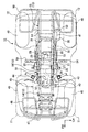
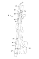
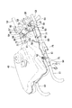
図1乃至図6は本発明の一実施形態を示すもので、図1は本発明に係る車両のエンジン補器類の配置構造の一実施形態を搭載した車両の側面図、図2は図1に示した車両の平面図、図3は図1に示した車両に用いたヒートガードの平面図、図4は図3に示したヒートガードの側面図、図5は図3に示したヒートガードの背面図、図6は図3に示したヒートガードの車体への取付け状態を説明する一部破断外観斜視図である。なお、以下の説明における前後左右等の向きは、特に記載が無ければ車両における向きと同一とする。また、図中矢印FRは車両前方を、矢印LHは車両左方を、矢印UPは車両上方をそれぞれ示す。
DESCRIPTION OF EXEMPLARY EMBODIMENTS Hereinafter, a preferred embodiment of an arrangement structure of engine auxiliary devices for a vehicle according to the invention will be described in detail with reference to the drawings.
1 to 6 show an embodiment of the present invention. FIG. 1 is a side view of a vehicle equipped with an embodiment of a vehicle engine accessory arrangement structure according to the present invention. FIG. 3 is a plan view of a heat guard used in the vehicle shown in FIG. 1, FIG. 4 is a side view of the heat guard shown in FIG. 3, and FIG. 5 is a heat guard shown in FIG. FIG. 6 is a partially broken external perspective view for explaining a mounting state of the heat guard shown in FIG. 3 to the vehicle body. In the following description, the directions such as front, rear, left and right are the same as those in the vehicle unless otherwise specified. In the figure, the arrow FR indicates the front of the vehicle, the arrow LH indicates the left side of the vehicle, and the arrow UP indicates the upper side of the vehicle.
図1及び図2に示すように、車両のエンジン補器類の配置構造を搭載した車両10は、小型軽量に構成された車体の前後に、比較的大径の低圧バルーンタイヤである左右の前輪11及び後輪12を備えることで、最低地上高を大きく確保し、主に不整地での走破性を高めた不整地走行用車両、所謂、ATV(All Terrain Vehicle)である。各前輪11及び後輪12は、車体フレーム13に有するフロントフレーム14及びリアフレーム15において、フロントサスペンション16及びリアサスペンション17を介して懸架されている。
As shown in FIGS. 1 and 2, a
車体フレーム13の車体略中央部に配置されたセンタフレーム18には、原動機としてのエンジン19が搭載される。エンジン19は、例えば水冷式の単気筒レシプロエンジンであり、クランクシャフトの回転軸線を車両前後方向に沿って配した縦置きレイアウトとされる。エンジン19は、そのクランクケース20上にシリンダヘッド21が立設された構成を有し、クランクケース20の前部及び後部における車体左右中央よりも左側にオフセットした部位からは、前後方向にフロント側出力軸22とリア側出力軸23とがそれぞれ前方と後方とに向けて導出される。
An
各出力軸22,23は、それぞれフロントプロペラシャフト24とリアプロペラシャフト25及びフロントファイナルリダクションギアユニット26とリアファイナルリダクションギアユニット27を介して各前輪11と各後輪12とに連結されているために、エンジン19からの出力が、クランクケース20内に収容された不図示の変速機を介した後に、各出力軸22,23から各ドライブシャフト24,25及び各ファイナルリダクションギアユニット26,27を介して各前輪11及び各後輪12にそれぞれ伝達される。
Each
エンジン19のシリンダヘッド21の後方部にはスロットルバルブ28がインテークマニホールド29を通じて接続されており、スロットルバルブ28の後方部はコネクティングチューブ30を通じてエアクリーナ31に連通接続される。エアクリーナ31のエアクリーナケース32には、シュノーケルダクト33が連通接続される。このシュノーケルダクト33は、エンジン19の輻射熱の影響のない車体上方部で開放されている。エアクリーナケース32には、不図示の温度センサが取り付けられている。
A
また、シリンダヘッド21の前部にはエキゾーストパイプ34が不図示のエキゾーストマニホールドを通じて接続される。エキゾーストパイプ34は、シリンダヘッド21の前方に延びた後に折り返し、シリンダヘッド21の左方を通過しながら後方に向かって延びて、その先端部が車体後部に配されたマフラ35に連通接続される。なお、フロントサスペンション16の前方にはエンジン19冷却用のラジエータ36が配置され、エンジン19の前方にはインジェクタ(図6参照)37に高圧の燃料を圧送する燃料ポンプ38が配置される。
Further, an
また、車体左右中央部には、前側から順に、ステアリングシャフト39、燃料タンク40、及び鞍乗りシート41が配設される。ステアリングシャフト39の下端部はフロントフレーム14の前端寄りに配置されたヘッドパイプ42を介して不図示の前輪操舵機構に連結されており、ステアリングシャフト39の上端部にはハンドル43が取り付けられている。なお、スロットルバルブ28に連結されている不図示のアクセル機構は、車両10が走行中に前後左右からの強い反動を受けるために、車両のコントロールをし易くするために、右グリップ40等の回動グリップに内蔵せずに独立して別所に設けられている。
In addition, a steering
車体フレーム13の前部には、車体前部を覆う樹脂製の車体カバー45と、各前輪11をその上方から後方に渡って覆う同じく樹脂製のフロントフェンダ46と、主に鋼材からなるフロントプロテクタ47と、フロントキャリア48とが取り付けられる。また、車体フレーム13の後部には、各後輪12をその上方から前方に渡って覆う樹脂製のリアフェンダ49と、主に鋼材からなるリアキャリア50とが取り付けられる。
At the front part of the
車体フレーム13は、複数種の鋼材を溶接等により一体的に結合してなるものであり、左右のアッパパイプ51とロアパイプ52とを用いて閉ループ構造を形成し、かつこれらを複数のクロスメンバを介して結合することで、車体左右中央部において前後に長いボックス構造を形成している。
The
各アッパパイプ51は、車体フレーム13の上部外側においてやや後下がりに傾斜して配されて車体フレーム13の下部外側において略水平に配されるロアパイプ52に後方部で結合されている。各アッパパイプ51は、後方部で各シートフレーム53に結合され、各ロアパイプ52の中央部には左右にステップ54が固定される。
Each of the
また、各アッパパイプ51の後方下部には、前後方向に扁平な略三角形状をなす左右のスイングアーム支持部55がそれぞれ一体的に設けられており、各スイングアーム支持部55に、リアファイナルリダクションギアユニット27が固定されたスイングアーム56が回動自在に連結されている。
In addition, left and right swing
そして、アッパパイプ51上にヒートガード70が取付けられている。ヒートガード70は、エンジン19及びスロットルバルブ28の上方であって燃料タンク40の下方に組み付けられている。
A
図3乃至図5に示すように、ヒートガード70は、本体71と、分離延長板72と、から主として構成されている。ヒートガード70は、熱を遮断して吸収しない樹脂を素材として、予め定められた厚さを有して作製されている。
As shown in FIGS. 3 to 5, the
本体71は、左右アッパパイプ51の間に架け渡されて配置される板部材であって、右方側にアッパパイプ51に沿って間隔を置いて半円筒形状に形成された第1,第2固定部73,74を有するとともに、左方側にアッパパイプ51に沿って間隔を置いて半円筒形状に形成された第3,第4,第5固定部75,76,77を有する。第1,第2固定部73,74は右側のアッパパイプ51に、第3,第4,第5固定部75,76,77は左側のアッパパイプ51に、それぞれ上方から被着され、例えばボルト等によって各アッパパイプ51に固定される。そして、第1,第4固定部73,76の前端寄りに、燃料タンク固定用ボルト孔78,79をそれぞれ有する。
The
また、本体71は、第1,第2固定部73,74側の右方に、2個のワイヤハーネス掛止部80,81を各アッパパイプ51の筒方向に並べて有し、第3,第4,第5固定部75,76,77側の左方に、2個の燃料配管掛止部82,83を各アッパパイプ51の筒方向に並べて有する。そして、本体71は、燃料配管掛止部82の前方に燃料タンク40の下方に設けられた燃料ポンプ38に向けて下方に湾曲する燃料配管引き出し用ガイド部84を有する。
The
分離延長板72は、本体71の後方に向けて四角形状の板状に延出して形成されており、本体71の上面85よりも高い位置にイグニションコイル取付部86を有し、このイグニションコイル取付部86の左方側に分離用舌片87を有する。イグニションコイル取付部86は、両端部にねじ孔88を有し、本体71側に本体71との間を隔離するための隔板89を立設している。分離用舌片87は切欠90を介してイグニションコイル取付部86の端部から左方に向けて突出したうえで下方に向けて折曲されている。
The
図6に示すように、ヒートガード70は、第1,第2固定部73,74が右側のアッパパイプ51に、第3,第4,第5固定部75,76,77が左側のアッパパイプ51に、それぞれ上方から被着されて固定されることで、エンジン(図1参照)19の上部に配置される。
As shown in FIG. 6, in the
ヒートガード70は、各アッパパイプ51上に架け渡されて固定されることで、分離延長板72がスロットルバルブ28の上部を覆うように配置される。そして、分離延長板72のイグニションコイル取付部86にイグニションコイル57がボルト止めされることで、イグニションコイル57が隔板89によって本体71から隔離されて配置される。
The
このとき、イグニションコイル57の一次側には、本体71上で、前方から後方へ向けて各ワイヤハーネス掛止部80,81に順次掛止されてきたワイヤハーネス58から分岐された不図示の枝配線が電気的に接続される。
At this time, on the primary side of the
そして、イグニションコイル57の2次側に、シリンダヘッド21にねじ込まれた不図示のスパークプラグに電気的に接続されるプラグコード59が接続される。ここで、プラグコード59は、イグニションコイル取付部87から左方に延出したうえで、分離延長板72の分離用舌片87に沿って下方へ引き出される。
A
また、燃料ポンプ(図1参照)38から上方に向けて引き出されてきた燃料配管60が、燃料配管引き出し用ガイド部84から本体71の上面85上に引き出され、前方から後方へ向けて各燃料配管掛止部82,83に順次掛止されたうえで、分離延長板72の分離用舌片87の下側に引き出されてインジェクタ37に連通接続される。
Further, the
ここで、燃料配管60は、ヒートガード70の本体71上を配策されることで、エンジン19から離れた場所を通ってインジェクタ37に至るために、エンジン19の輻射熱を受けることがないとともに、燃料配管引き出し用ガイド部84と各燃料配管掛止部82,83とによって折り曲げられずにインジェクタ37に連通される。
Here, the
このように、分離延長板72の分離用舌片87は、その上面にプラグコード59を配策し、その下面に燃料配管60を配策するために、イグニションコイル57の高電圧の2次電圧(電流)が印加(供給)されるプラグコード59を、燃料が流れる燃料配管60に対して独立して配策することができるために、簡単な構造でプラグコード59と燃料配管60とを分離することができる。
In this way, the
そして、ヒートガード70の第1,第3固定部73,75の燃料タンク固定用ボルト孔78,79を介して燃料タンク40が本体71の前側に組み付けられる。このとき、燃料タンク40は、中央部に一体成形されている、例えば金属製のベース61に、ダンパ付ボルト62が挿通され、ダンパ付ボルト62が第1,第4固定部73,76の燃料タンク固定用ボルト孔78,79にねじ込まれることで、車体振動を受けないようにして各アッパパイプ51に組み付けられる。
The
そして、ヒートガード70における本体71の後方側及び分離延長板72上に鞍乗りシート(図1参照)41が配置される。このとき、各アッパパイプ51の間に配置される一対の車体側フック64,64を介して鞍乗りシート41のシート側フック63,63の着脱作業が行われる。車体側フック64はシートフレーム53に固定されており、シート側フック63は鞍乗りシート41の裏面側にばね付勢により回動可能なように取り付けられている。したがって、分離延長板72がスロットルバルブ28及びインジェクタ37を覆って配置されているために、着脱作業時に車体側フック64,64に係止される鞍乗りシート41側のシート側フック63,63がスロットルバルブ28及びインジェクタ37に干渉することがないとともに、その作業に使用する工具等によってスロットルバルブ28及びインジェクタ37が損傷を受けることがない。
A saddle riding seat (see FIG. 1) 41 is disposed on the rear side of the
なお、ヒートガード70の本体71上及び分離延長板72上には、図示したイグニションコイル57に加えて、レギュレータやイグナイタ等の他のエンジン補器類を配置しても良い。
In addition to the illustrated
以上説明した本発明の一実施形態に係る車両10のエンジン補器類の配置構造では、ヒートガード70が、エンジン19の上方においてエンジン19と燃料配管60とを分離することで、エンジン19の輻射熱を燃料配管60に与えることがない。また、エンジン19の上方に配置されることで、スロットルバルブ28やインジェクタ37に泥や粉塵がかからないように保護したり、鞍乗りシート41の着脱作業時にスロットルバルブ28やインジェクタ37に鞍乗りシート41のフック等が干渉したりしないように保護することができる。また、イグニションコイル57を上部に取付けることで、イグニションコイル57をエンジン19の近くでエンジン19の輻射熱から保護して配置することができるとともにイグニションコイル57からエンジン19までを短い距離にできる。これにより、イグニションコイル57をエンジン19の近くに支障なく配置することができ、エンジン19の上部におけるスペースの有効利用を図って車両10のデザインを向上させることができる。
In the arrangement structure of the engine accessories of the
また、本実施形態に係る車両10のエンジン補器類の配置構造では、ヒートガード70の分離延長板72によって、イグニションコイル57において高電圧の2次電圧が印加されるプラグコード59を、燃料が流れる燃料配管60に対して独立して配策することができる。これにより、簡単な構造でイグニションコイル57のプラグコード59と燃料配管60とを分離することができるとともに、プラグコード59から発生するノイズが他のエンジン補器に悪影響を与えたりリークによる悪影響を生じたりすることがなくなって車両10の品質を保障することができる。
Further, in the arrangement structure of the engine accessories of the
また、本実施形態に係る車両10のエンジン補器類の配置構造では、車両10が、ATV車両であるために、不整地走行等の過酷な使用をされたとしても、イグニションコイル57が支障なく配置されていることで高い品質を長期的に維持することができる。
Further, in the arrangement structure of the engine auxiliary equipment of the
10 車両
19 エンジン
28 スロットルバルブ
41 鞍乗りシート(シート)
57 イグニションコイル(エンジン補器)
59 プラグコード(配線)
60 燃料配管、高圧配管
70 ヒートガード
72 分離延長板
10
57 Ignition coil (engine auxiliary equipment)
59 Plug cord (wiring)
60 Fuel piping, high-
Claims (2)
前記エンジン(19)の上部かつシート(41)の下部に配置されるエンジン補器(57)と、を備えた車両(10)のエンジン補器類の配置構造において、
前記エンジン(19)の上方であって該エンジン(19)と燃料配管(60)とを分離するとともに、前記スロットルバルブ(28)を保護し、前記エンジン補器(57)を上部に取付けるヒートガード(70)を有することを特徴とする車両(10)のエンジン補器類の配置構造。 A throttle valve (28) arranged around the engine (19);
An engine auxiliary device (57) disposed at the upper part of the engine (19) and at the lower part of the seat (41);
A heat guard above the engine (19) for separating the engine (19) and the fuel pipe (60), protecting the throttle valve (28), and mounting the engine accessory (57) on the top An arrangement structure of engine accessories of the vehicle (10), characterized by comprising (70).
前記燃料配管(60)が、前記エンジン(19)のインジェクタ(37)へ燃料を供給する高圧配管(60)であり、
前記ヒートガード(70)が、前記イグニションコイル(57)の配線(59)と、前記高圧配管(60)と、を分離する分離延長板(72)を備えることを特徴とする請求項1記載の車両(10)のエンジン補器類の配置構造。 The engine accessory (57) is an ignition coil (57) for generating a high voltage,
The fuel pipe (60) is a high-pressure pipe (60) for supplying fuel to an injector (37) of the engine (19);
The said heat guard (70) is provided with the isolation | separation extension plate (72) which isolate | separates the wiring (59) of the said ignition coil (57), and the said high voltage | pressure piping (60). Arrangement structure of engine accessories of vehicle (10).
Priority Applications (3)
| Application Number | Priority Date | Filing Date | Title |
|---|---|---|---|
| JP2005188378A JP4535943B2 (en) | 2005-06-28 | 2005-06-28 | Arrangement structure of vehicle engine accessories |
| AU2006202160A AU2006202160B2 (en) | 2005-06-28 | 2006-05-22 | Engine accessory layout structure for vehicle |
| US11/473,269 US7370625B2 (en) | 2005-06-28 | 2006-06-23 | Engine accessory layout structure for vehicle |
Applications Claiming Priority (1)
| Application Number | Priority Date | Filing Date | Title |
|---|---|---|---|
| JP2005188378A JP4535943B2 (en) | 2005-06-28 | 2005-06-28 | Arrangement structure of vehicle engine accessories |
Publications (2)
| Publication Number | Publication Date |
|---|---|
| JP2007009727A true JP2007009727A (en) | 2007-01-18 |
| JP4535943B2 JP4535943B2 (en) | 2010-09-01 |
Family
ID=37565804
Family Applications (1)
| Application Number | Title | Priority Date | Filing Date |
|---|---|---|---|
| JP2005188378A Expired - Fee Related JP4535943B2 (en) | 2005-06-28 | 2005-06-28 | Arrangement structure of vehicle engine accessories |
Country Status (3)
| Country | Link |
|---|---|
| US (1) | US7370625B2 (en) |
| JP (1) | JP4535943B2 (en) |
| AU (1) | AU2006202160B2 (en) |
Cited By (4)
| Publication number | Priority date | Publication date | Assignee | Title |
|---|---|---|---|---|
| KR100873161B1 (en) * | 2007-03-02 | 2008-12-10 | 최상석 | Glass bead-type reflective paper having a printing layer suitable for mass production and its manufacturing method |
| JP2011046346A (en) * | 2009-08-28 | 2011-03-10 | Honda Motor Co Ltd | Motorcycle |
| JP2012224130A (en) * | 2011-04-15 | 2012-11-15 | Honda Motor Co Ltd | Saddle type vehicle |
| US10882577B2 (en) | 2018-08-31 | 2021-01-05 | Honda Motor Co., Ltd. | Saddled vehicle |
Families Citing this family (8)
| Publication number | Priority date | Publication date | Assignee | Title |
|---|---|---|---|---|
| CA2496200C (en) * | 2004-02-06 | 2008-10-07 | Honda Motor Co., Ltd. | A fuel injection system for a saddle ride type four-wheel vehicle |
| JP5129632B2 (en) * | 2008-03-27 | 2013-01-30 | 本田技研工業株式会社 | Harness holding structure for saddle-ride type vehicles |
| US9169812B2 (en) | 2012-10-11 | 2015-10-27 | Honda Motor Co., Ltd. | Vehicular engine assembly having snorkel and vehicle including same |
| US8910472B2 (en) * | 2012-12-27 | 2014-12-16 | Kawasaki Jukogyo Kabushiki Kaisha | Utility vehicle |
| JP6616646B2 (en) * | 2015-10-08 | 2019-12-04 | 川崎重工業株式会社 | Heat shield structure for the intake system of motorcycle engines |
| JP2018123766A (en) * | 2017-02-01 | 2018-08-09 | トヨタ自動車株式会社 | Fuel pipeline support structure |
| JP2024146565A (en) * | 2023-03-31 | 2024-10-15 | ヤマハ発動機株式会社 | vehicle |
| FR3164952A1 (en) * | 2024-07-26 | 2026-01-30 | Renault Sas | Multifunctional support for gearbox |
Citations (5)
| Publication number | Priority date | Publication date | Assignee | Title |
|---|---|---|---|---|
| JPS6072784U (en) * | 1983-10-27 | 1985-05-22 | ヤマハ発動機株式会社 | Motorcycle heat shield device |
| JPH0986467A (en) * | 1995-09-26 | 1997-03-31 | Suzuki Motor Corp | Intake system mudproof structure of unit swing type engine |
| JPH09328088A (en) * | 1996-06-10 | 1997-12-22 | Kawasaki Heavy Ind Ltd | Saddle-type vehicle |
| JP2003089376A (en) * | 2001-09-17 | 2003-03-25 | Honda Motor Co Ltd | Lay-out structure of engine auxiliaries in vehicle such as motor-bicycle |
| JP2004270589A (en) * | 2003-03-10 | 2004-09-30 | Suzuki Motor Corp | Fuel supply device for saddle riding type vehicle |
-
2005
- 2005-06-28 JP JP2005188378A patent/JP4535943B2/en not_active Expired - Fee Related
-
2006
- 2006-05-22 AU AU2006202160A patent/AU2006202160B2/en not_active Ceased
- 2006-06-23 US US11/473,269 patent/US7370625B2/en not_active Expired - Fee Related
Patent Citations (5)
| Publication number | Priority date | Publication date | Assignee | Title |
|---|---|---|---|---|
| JPS6072784U (en) * | 1983-10-27 | 1985-05-22 | ヤマハ発動機株式会社 | Motorcycle heat shield device |
| JPH0986467A (en) * | 1995-09-26 | 1997-03-31 | Suzuki Motor Corp | Intake system mudproof structure of unit swing type engine |
| JPH09328088A (en) * | 1996-06-10 | 1997-12-22 | Kawasaki Heavy Ind Ltd | Saddle-type vehicle |
| JP2003089376A (en) * | 2001-09-17 | 2003-03-25 | Honda Motor Co Ltd | Lay-out structure of engine auxiliaries in vehicle such as motor-bicycle |
| JP2004270589A (en) * | 2003-03-10 | 2004-09-30 | Suzuki Motor Corp | Fuel supply device for saddle riding type vehicle |
Cited By (4)
| Publication number | Priority date | Publication date | Assignee | Title |
|---|---|---|---|---|
| KR100873161B1 (en) * | 2007-03-02 | 2008-12-10 | 최상석 | Glass bead-type reflective paper having a printing layer suitable for mass production and its manufacturing method |
| JP2011046346A (en) * | 2009-08-28 | 2011-03-10 | Honda Motor Co Ltd | Motorcycle |
| JP2012224130A (en) * | 2011-04-15 | 2012-11-15 | Honda Motor Co Ltd | Saddle type vehicle |
| US10882577B2 (en) | 2018-08-31 | 2021-01-05 | Honda Motor Co., Ltd. | Saddled vehicle |
Also Published As
| Publication number | Publication date |
|---|---|
| AU2006202160B2 (en) | 2011-06-16 |
| US20060288975A1 (en) | 2006-12-28 |
| JP4535943B2 (en) | 2010-09-01 |
| AU2006202160A1 (en) | 2007-01-11 |
| US7370625B2 (en) | 2008-05-13 |
Similar Documents
| Publication | Publication Date | Title |
|---|---|---|
| US7730986B2 (en) | Electric component arrangement structure for vehicle, vehicle having the same, and method for arranging electric component in vehicle | |
| US9187049B2 (en) | Saddled vehicle | |
| JP5905091B2 (en) | Saddle riding | |
| JP4535943B2 (en) | Arrangement structure of vehicle engine accessories | |
| US8567542B2 (en) | Intake air routing structure for a vehicle, and vehicle including same | |
| CN102126522B (en) | vehicle | |
| JP6238329B2 (en) | Engine control unit mounting structure for motorcycles | |
| JP5129632B2 (en) | Harness holding structure for saddle-ride type vehicles | |
| US20080099263A1 (en) | Saddle ride type vehicle | |
| JP6130119B2 (en) | Motorcycle | |
| JP2011000912A (en) | Electrical component mounting structure for motorcycle | |
| JP2016117349A (en) | Saddle-riding type vehicle | |
| US11884360B2 (en) | Electrical component mounting structure for saddled vehicle | |
| US8662224B2 (en) | Arrangement of electric part | |
| JP4574415B2 (en) | Saddle riding vehicle | |
| US8074756B2 (en) | Straddle-type rough-road running vehicle | |
| JP5098103B2 (en) | Headlight support structure for saddle-ride type vehicles | |
| JP4574414B2 (en) | Saddle riding vehicle | |
| JP2018134907A (en) | Saddle-riding type vehicle | |
| JP5764172B2 (en) | Fuel supply system for saddle-ride type vehicles | |
| WO2011117919A1 (en) | Air intake system arrangement structure for saddle riding type vehicle | |
| JP6491043B2 (en) | Mounting structure for motorcycle electrical components | |
| JP2010234946A (en) | Motorcycle | |
| JP2023047999A (en) | saddle-riding vehicle | |
| WO2020121473A1 (en) | Saddled vehicle |
Legal Events
| Date | Code | Title | Description |
|---|---|---|---|
| A621 | Written request for application examination |
Free format text: JAPANESE INTERMEDIATE CODE: A621 Effective date: 20071127 |
|
| RD04 | Notification of resignation of power of attorney |
Free format text: JAPANESE INTERMEDIATE CODE: A7424 Effective date: 20071129 |
|
| A977 | Report on retrieval |
Free format text: JAPANESE INTERMEDIATE CODE: A971007 Effective date: 20100121 |
|
| A131 | Notification of reasons for refusal |
Free format text: JAPANESE INTERMEDIATE CODE: A131 Effective date: 20100126 |
|
| A521 | Request for written amendment filed |
Free format text: JAPANESE INTERMEDIATE CODE: A523 Effective date: 20100316 |
|
| RD03 | Notification of appointment of power of attorney |
Free format text: JAPANESE INTERMEDIATE CODE: A7423 Effective date: 20100316 |
|
| RD04 | Notification of resignation of power of attorney |
Free format text: JAPANESE INTERMEDIATE CODE: A7424 Effective date: 20100317 |
|
| TRDD | Decision of grant or rejection written | ||
| A01 | Written decision to grant a patent or to grant a registration (utility model) |
Free format text: JAPANESE INTERMEDIATE CODE: A01 Effective date: 20100608 |
|
| A01 | Written decision to grant a patent or to grant a registration (utility model) |
Free format text: JAPANESE INTERMEDIATE CODE: A01 |
|
| A61 | First payment of annual fees (during grant procedure) |
Free format text: JAPANESE INTERMEDIATE CODE: A61 Effective date: 20100615 |
|
| FPAY | Renewal fee payment (event date is renewal date of database) |
Free format text: PAYMENT UNTIL: 20130625 Year of fee payment: 3 |
|
| R150 | Certificate of patent or registration of utility model |
Ref document number: 4535943 Country of ref document: JP Free format text: JAPANESE INTERMEDIATE CODE: R150 Free format text: JAPANESE INTERMEDIATE CODE: R150 |
|
| FPAY | Renewal fee payment (event date is renewal date of database) |
Free format text: PAYMENT UNTIL: 20130625 Year of fee payment: 3 |
|
| FPAY | Renewal fee payment (event date is renewal date of database) |
Free format text: PAYMENT UNTIL: 20140625 Year of fee payment: 4 |
|
| LAPS | Cancellation because of no payment of annual fees |