JP2007009727A - 車両のエンジン補器類の配置構造 - Google Patents
車両のエンジン補器類の配置構造 Download PDFInfo
- Publication number
- JP2007009727A JP2007009727A JP2005188378A JP2005188378A JP2007009727A JP 2007009727 A JP2007009727 A JP 2007009727A JP 2005188378 A JP2005188378 A JP 2005188378A JP 2005188378 A JP2005188378 A JP 2005188378A JP 2007009727 A JP2007009727 A JP 2007009727A
- Authority
- JP
- Japan
- Prior art keywords
- engine
- vehicle
- arrangement structure
- pipe
- ignition coil
- Prior art date
- Legal status (The legal status is an assumption and is not a legal conclusion. Google has not performed a legal analysis and makes no representation as to the accuracy of the status listed.)
- Granted
Links
Images


Classifications
-
- F—MECHANICAL ENGINEERING; LIGHTING; HEATING; WEAPONS; BLASTING
- F02—COMBUSTION ENGINES; HOT-GAS OR COMBUSTION-PRODUCT ENGINE PLANTS
- F02B—INTERNAL-COMBUSTION PISTON ENGINES; COMBUSTION ENGINES IN GENERAL
- F02B61/00—Adaptations of engines for driving vehicles or for driving propellers; Combinations of engines with gearing
- F02B61/02—Adaptations of engines for driving vehicles or for driving propellers; Combinations of engines with gearing for driving cycles
Landscapes
- Engineering & Computer Science (AREA)
- Chemical & Material Sciences (AREA)
- Combustion & Propulsion (AREA)
- Mechanical Engineering (AREA)
- General Engineering & Computer Science (AREA)
- Automatic Cycles, And Cycles In General (AREA)
- Cooling, Air Intake And Gas Exhaust, And Fuel Tank Arrangements In Propulsion Units (AREA)
- Fuel-Injection Apparatus (AREA)
Abstract
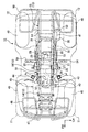
【解決手段】 エンジン19の周辺に配置されたスロットルバルブ28と、エンジン19の上部かつシート41の下部に配置されるエンジン補器と、を備え、エンジン19の上方であってエンジン19と燃料配管とを分離するとともに、スロットルバルブ28を保護し、エンジン補器を上部に取付けるヒートガード70を有する車両10のエンジン補器類の配置構造。
【選択図】 図1
Description
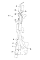
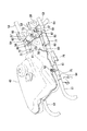
図1乃至図6は本発明の一実施形態を示すもので、図1は本発明に係る車両のエンジン補器類の配置構造の一実施形態を搭載した車両の側面図、図2は図1に示した車両の平面図、図3は図1に示した車両に用いたヒートガードの平面図、図4は図3に示したヒートガードの側面図、図5は図3に示したヒートガードの背面図、図6は図3に示したヒートガードの車体への取付け状態を説明する一部破断外観斜視図である。なお、以下の説明における前後左右等の向きは、特に記載が無ければ車両における向きと同一とする。また、図中矢印FRは車両前方を、矢印LHは車両左方を、矢印UPは車両上方をそれぞれ示す。
19 エンジン
28 スロットルバルブ
41 鞍乗りシート(シート)
57 イグニションコイル(エンジン補器)
59 プラグコード(配線)
60 燃料配管、高圧配管
70 ヒートガード
72 分離延長板
Claims (2)
- エンジン(19)の周辺に配置されたスロットルバルブ(28)と、
前記エンジン(19)の上部かつシート(41)の下部に配置されるエンジン補器(57)と、を備えた車両(10)のエンジン補器類の配置構造において、
前記エンジン(19)の上方であって該エンジン(19)と燃料配管(60)とを分離するとともに、前記スロットルバルブ(28)を保護し、前記エンジン補器(57)を上部に取付けるヒートガード(70)を有することを特徴とする車両(10)のエンジン補器類の配置構造。 - 前記エンジン補器(57)が、高電圧を発生するイグニションコイル(57)であって、
前記燃料配管(60)が、前記エンジン(19)のインジェクタ(37)へ燃料を供給する高圧配管(60)であり、
前記ヒートガード(70)が、前記イグニションコイル(57)の配線(59)と、前記高圧配管(60)と、を分離する分離延長板(72)を備えることを特徴とする請求項1記載の車両(10)のエンジン補器類の配置構造。
Priority Applications (3)
| Application Number | Priority Date | Filing Date | Title |
|---|---|---|---|
| JP2005188378A JP4535943B2 (ja) | 2005-06-28 | 2005-06-28 | 車両のエンジン補器類の配置構造 |
| AU2006202160A AU2006202160B2 (en) | 2005-06-28 | 2006-05-22 | Engine accessory layout structure for vehicle |
| US11/473,269 US7370625B2 (en) | 2005-06-28 | 2006-06-23 | Engine accessory layout structure for vehicle |
Applications Claiming Priority (1)
| Application Number | Priority Date | Filing Date | Title |
|---|---|---|---|
| JP2005188378A JP4535943B2 (ja) | 2005-06-28 | 2005-06-28 | 車両のエンジン補器類の配置構造 |
Publications (2)
| Publication Number | Publication Date |
|---|---|
| JP2007009727A true JP2007009727A (ja) | 2007-01-18 |
| JP4535943B2 JP4535943B2 (ja) | 2010-09-01 |
Family
ID=37565804
Family Applications (1)
| Application Number | Title | Priority Date | Filing Date |
|---|---|---|---|
| JP2005188378A Expired - Fee Related JP4535943B2 (ja) | 2005-06-28 | 2005-06-28 | 車両のエンジン補器類の配置構造 |
Country Status (3)
| Country | Link |
|---|---|
| US (1) | US7370625B2 (ja) |
| JP (1) | JP4535943B2 (ja) |
| AU (1) | AU2006202160B2 (ja) |
Cited By (4)
| Publication number | Priority date | Publication date | Assignee | Title |
|---|---|---|---|---|
| KR100873161B1 (ko) * | 2007-03-02 | 2008-12-10 | 최상석 | 대량생산에 적합한 인쇄층을 가지는 유리구슬 타입 반사지및 그 제조방법 |
| JP2011046346A (ja) * | 2009-08-28 | 2011-03-10 | Honda Motor Co Ltd | 自動二輪車 |
| JP2012224130A (ja) * | 2011-04-15 | 2012-11-15 | Honda Motor Co Ltd | 鞍乗り型車両 |
| US10882577B2 (en) | 2018-08-31 | 2021-01-05 | Honda Motor Co., Ltd. | Saddled vehicle |
Families Citing this family (8)
| Publication number | Priority date | Publication date | Assignee | Title |
|---|---|---|---|---|
| CA2496200C (en) * | 2004-02-06 | 2008-10-07 | Honda Motor Co., Ltd. | A fuel injection system for a saddle ride type four-wheel vehicle |
| JP5129632B2 (ja) * | 2008-03-27 | 2013-01-30 | 本田技研工業株式会社 | 鞍乗り型車両のハーネス保持構造 |
| US9169812B2 (en) | 2012-10-11 | 2015-10-27 | Honda Motor Co., Ltd. | Vehicular engine assembly having snorkel and vehicle including same |
| US8910472B2 (en) * | 2012-12-27 | 2014-12-16 | Kawasaki Jukogyo Kabushiki Kaisha | Utility vehicle |
| JP6616646B2 (ja) * | 2015-10-08 | 2019-12-04 | 川崎重工業株式会社 | 自動二輪車のエンジンの吸気系の遮熱構造 |
| JP2018123766A (ja) * | 2017-02-01 | 2018-08-09 | トヨタ自動車株式会社 | 燃料配管の支持構造 |
| JP2024146565A (ja) * | 2023-03-31 | 2024-10-15 | ヤマハ発動機株式会社 | 車両 |
| FR3164952A1 (fr) * | 2024-07-26 | 2026-01-30 | Renault Sas | Support multifonction pour boite de vitesse |
Citations (5)
| Publication number | Priority date | Publication date | Assignee | Title |
|---|---|---|---|---|
| JPS6072784U (ja) * | 1983-10-27 | 1985-05-22 | ヤマハ発動機株式会社 | 自動二輪車の遮熱装置 |
| JPH0986467A (ja) * | 1995-09-26 | 1997-03-31 | Suzuki Motor Corp | ユニットスイング式エンジンの吸気系防泥構造 |
| JPH09328088A (ja) * | 1996-06-10 | 1997-12-22 | Kawasaki Heavy Ind Ltd | 鞍乗型車両 |
| JP2003089376A (ja) * | 2001-09-17 | 2003-03-25 | Honda Motor Co Ltd | 自動二輪車等車両におけるエンジン補器類の配置構造 |
| JP2004270589A (ja) * | 2003-03-10 | 2004-09-30 | Suzuki Motor Corp | 鞍乗型車両の燃料供給装置 |
-
2005
- 2005-06-28 JP JP2005188378A patent/JP4535943B2/ja not_active Expired - Fee Related
-
2006
- 2006-05-22 AU AU2006202160A patent/AU2006202160B2/en not_active Ceased
- 2006-06-23 US US11/473,269 patent/US7370625B2/en not_active Expired - Fee Related
Patent Citations (5)
| Publication number | Priority date | Publication date | Assignee | Title |
|---|---|---|---|---|
| JPS6072784U (ja) * | 1983-10-27 | 1985-05-22 | ヤマハ発動機株式会社 | 自動二輪車の遮熱装置 |
| JPH0986467A (ja) * | 1995-09-26 | 1997-03-31 | Suzuki Motor Corp | ユニットスイング式エンジンの吸気系防泥構造 |
| JPH09328088A (ja) * | 1996-06-10 | 1997-12-22 | Kawasaki Heavy Ind Ltd | 鞍乗型車両 |
| JP2003089376A (ja) * | 2001-09-17 | 2003-03-25 | Honda Motor Co Ltd | 自動二輪車等車両におけるエンジン補器類の配置構造 |
| JP2004270589A (ja) * | 2003-03-10 | 2004-09-30 | Suzuki Motor Corp | 鞍乗型車両の燃料供給装置 |
Cited By (4)
| Publication number | Priority date | Publication date | Assignee | Title |
|---|---|---|---|---|
| KR100873161B1 (ko) * | 2007-03-02 | 2008-12-10 | 최상석 | 대량생산에 적합한 인쇄층을 가지는 유리구슬 타입 반사지및 그 제조방법 |
| JP2011046346A (ja) * | 2009-08-28 | 2011-03-10 | Honda Motor Co Ltd | 自動二輪車 |
| JP2012224130A (ja) * | 2011-04-15 | 2012-11-15 | Honda Motor Co Ltd | 鞍乗り型車両 |
| US10882577B2 (en) | 2018-08-31 | 2021-01-05 | Honda Motor Co., Ltd. | Saddled vehicle |
Also Published As
| Publication number | Publication date |
|---|---|
| AU2006202160B2 (en) | 2011-06-16 |
| US20060288975A1 (en) | 2006-12-28 |
| JP4535943B2 (ja) | 2010-09-01 |
| AU2006202160A1 (en) | 2007-01-11 |
| US7370625B2 (en) | 2008-05-13 |
Similar Documents
| Publication | Publication Date | Title |
|---|---|---|
| US7730986B2 (en) | Electric component arrangement structure for vehicle, vehicle having the same, and method for arranging electric component in vehicle | |
| US9187049B2 (en) | Saddled vehicle | |
| JP5905091B2 (ja) | 鞍乗り型車両 | |
| JP4535943B2 (ja) | 車両のエンジン補器類の配置構造 | |
| US8567542B2 (en) | Intake air routing structure for a vehicle, and vehicle including same | |
| CN102126522B (zh) | 车辆 | |
| JP6238329B2 (ja) | 自動二輪車用エンジン制御ユニット取付構造 | |
| JP5129632B2 (ja) | 鞍乗り型車両のハーネス保持構造 | |
| US20080099263A1 (en) | Saddle ride type vehicle | |
| JP6130119B2 (ja) | 自動二輪車 | |
| JP2011000912A (ja) | 自動二輪車の電装品取付構造 | |
| JP2016117349A (ja) | 鞍乗型車両 | |
| US11884360B2 (en) | Electrical component mounting structure for saddled vehicle | |
| US8662224B2 (en) | Arrangement of electric part | |
| JP4574415B2 (ja) | 鞍乗型車両 | |
| US8074756B2 (en) | Straddle-type rough-road running vehicle | |
| JP5098103B2 (ja) | 鞍乗り型車両のヘッドライト支持構造 | |
| JP4574414B2 (ja) | 鞍乗型車両 | |
| JP2018134907A (ja) | 鞍乗型車両 | |
| JP5764172B2 (ja) | 鞍乗り型車両の燃料供給装置 | |
| WO2011117919A1 (ja) | 鞍乗り型車両の吸気系の配置構造 | |
| JP6491043B2 (ja) | 自動二輪車の電装品取付構造 | |
| JP2010234946A (ja) | 自動二輪車 | |
| JP2023047999A (ja) | 鞍乗り型車両 | |
| WO2020121473A1 (ja) | 鞍乗り型車両 |
Legal Events
| Date | Code | Title | Description |
|---|---|---|---|
| A621 | Written request for application examination |
Free format text: JAPANESE INTERMEDIATE CODE: A621 Effective date: 20071127 |
|
| RD04 | Notification of resignation of power of attorney |
Free format text: JAPANESE INTERMEDIATE CODE: A7424 Effective date: 20071129 |
|
| A977 | Report on retrieval |
Free format text: JAPANESE INTERMEDIATE CODE: A971007 Effective date: 20100121 |
|
| A131 | Notification of reasons for refusal |
Free format text: JAPANESE INTERMEDIATE CODE: A131 Effective date: 20100126 |
|
| A521 | Request for written amendment filed |
Free format text: JAPANESE INTERMEDIATE CODE: A523 Effective date: 20100316 |
|
| RD03 | Notification of appointment of power of attorney |
Free format text: JAPANESE INTERMEDIATE CODE: A7423 Effective date: 20100316 |
|
| RD04 | Notification of resignation of power of attorney |
Free format text: JAPANESE INTERMEDIATE CODE: A7424 Effective date: 20100317 |
|
| TRDD | Decision of grant or rejection written | ||
| A01 | Written decision to grant a patent or to grant a registration (utility model) |
Free format text: JAPANESE INTERMEDIATE CODE: A01 Effective date: 20100608 |
|
| A01 | Written decision to grant a patent or to grant a registration (utility model) |
Free format text: JAPANESE INTERMEDIATE CODE: A01 |
|
| A61 | First payment of annual fees (during grant procedure) |
Free format text: JAPANESE INTERMEDIATE CODE: A61 Effective date: 20100615 |
|
| FPAY | Renewal fee payment (event date is renewal date of database) |
Free format text: PAYMENT UNTIL: 20130625 Year of fee payment: 3 |
|
| R150 | Certificate of patent or registration of utility model |
Ref document number: 4535943 Country of ref document: JP Free format text: JAPANESE INTERMEDIATE CODE: R150 Free format text: JAPANESE INTERMEDIATE CODE: R150 |
|
| FPAY | Renewal fee payment (event date is renewal date of database) |
Free format text: PAYMENT UNTIL: 20130625 Year of fee payment: 3 |
|
| FPAY | Renewal fee payment (event date is renewal date of database) |
Free format text: PAYMENT UNTIL: 20140625 Year of fee payment: 4 |
|
| LAPS | Cancellation because of no payment of annual fees |