JP2007155358A - Leak location inspection structure for buried gas pipe - Google Patents
Leak location inspection structure for buried gas pipe Download PDFInfo
- Publication number
- JP2007155358A JP2007155358A JP2005347028A JP2005347028A JP2007155358A JP 2007155358 A JP2007155358 A JP 2007155358A JP 2005347028 A JP2005347028 A JP 2005347028A JP 2005347028 A JP2005347028 A JP 2005347028A JP 2007155358 A JP2007155358 A JP 2007155358A
- Authority
- JP
- Japan
- Prior art keywords
- stopper
- inspection
- gas pipe
- pipe
- pressure
- Prior art date
- Legal status (The legal status is an assumption and is not a legal conclusion. Google has not performed a legal analysis and makes no representation as to the accuracy of the status listed.)
- Pending
Links
Images


Landscapes
- Examining Or Testing Airtightness (AREA)
Abstract
【課題】 この発明は、埋設ガス管内のガスの漏洩個所を廉価に且つガス管やストッパを傷めずに検査し特定することができる埋設ガス管の漏洩箇所検査構造に関する。
【解決手段】 埋設ガス管の一方の口部を密封してガス管内の圧力を検査する管内圧力検査ゲージを設け、埋設ガス管内に挿通冶具とストッパ加圧チューブ付きのストッパとを挿入し、検査区間の他方の口部から前記挿通冶具を吸引して引っ張り、前記ストッパ加圧チューブをストッパ膨出手段に接続して前記気密検査ストッパとの間を密封区間とし、前記ストッパの位置を他方の口部方向へ段階的に移動させながら密閉区間を広げてガスの漏洩の有無を検査することを特徴とする。
【選択図】 図1PROBLEM TO BE SOLVED: To provide a leakage point inspection structure for a buried gas pipe capable of inspecting and specifying a gas leak point in the buried gas pipe at low cost without damaging the gas pipe and the stopper.
SOLUTION: An in-pipe pressure inspection gauge for inspecting the pressure in the gas pipe by sealing one of the ports of the buried gas pipe is provided, and an insertion tool and a stopper with a stopper pressure tube are inserted into the buried gas pipe for inspection. The insertion jig is sucked and pulled from the other mouth part of the section, the stopper pressurizing tube is connected to the stopper bulging means, and the airtight inspection stopper is defined as a sealed section, and the position of the stopper is the other mouth. It is characterized by inspecting the presence or absence of gas leakage by expanding the sealed section while moving in a stepwise direction.
[Selection] Figure 1
Description
この発明は、埋設ガス管内のガスの漏洩個所を廉価に且つガス管やストッパを傷めずに検査し特定することができる埋設ガス管の漏洩箇所検査構造に関する。 The present invention relates to a buried gas pipe leakage point inspection structure capable of inspecting and specifying a gas leakage point in a buried gas pipe at low cost and without damaging the gas pipe or stopper.
埋設ガス管に漏洩が発生した場合には、従来、地表部でガス検知器を用いて検査することで漏洩箇所を特定するのが一般的であるが、地表部がコンクリートや平板であったり、植栽などであったり、ガス管の周りに水道管や排水管などの他の埋設物が近接し空洞ができている場合には、漏洩箇所の直上の地表部にガスが検知できずに、局所の掘削では漏れ箇所の特定と修理ができないケースが発生する。また、地下水位が高い場合はガス漏洩せず、ガス管内への差し水による供給支障が発生する場合もある。この場合は、漏洩箇所の代わりに管内部を調査して差し水箇所を特定するため、採水さらに管内カメラ調査を実施するが、カメラへッドが通過できない曲がりがあったり、調査時に差し水がなく確認できない場合があったり、管内部の腐食などにより差し水箇所を断定できないことがある。
そこで、ガス遺漏箇所検出のため、従来、特開2003−121294号のガス遺漏箇所検出方法および装置のように、例えば家屋側のコックを閉じておき、他方側からガス管内に装置本体を挿入し接続用筒体を介して挿入用案内体を有する抽水ヘッドとストッパ(ガスバッグ)とを取り替えながら埋設ガス管内を移動させながら密閉区間を狭めて漏洩個所の検出を行っている。
また、特開平9−288033号の既設配管系の漏洩検査用密封栓構造およびこれを基にした埋設管漏洩位置検査装置としてのリークロケータ(商品名 東京ガス株式会社販売)が知られている。
この装置30は、図6に示すように、活管状態の埋設ガス管のメータ立管側よりストッパ31・チューブ32を回転させながら挿入し、気密ユニット33や生ガス漏出防止(水封管)により検査する。
前記ストッパ31は水圧により膨らませてシールする。このストッパ31を移動させながら気密検査し、圧力の変化の有無により、漏洩箇所を特定している。
しかし、この装置30では、適用長さが10m6曲がりと短いため、10m10曲がりや、長さが10mを越える物件の場合には対応できない。また、気密ユニットや水封管など装備が多いため、高価となる。
更に、これらの装置では、一方のコックを閉じておき、ストッパをガス管内を移動させるので、ストッパ防護はあるが、加圧時のバリによる破損が発生する可能性があり、またスケール除去ができないため、ストッパのシール性の阻害が発生する虞れがある。
Therefore, for the detection of a gas leak location, conventionally, for example, a house-side cock is closed and a device main body is inserted into the gas pipe from the other side as in the gas leak location detection method and apparatus of Japanese Patent Application Laid-Open No. 2003-121294. While changing the extraction head having the guide for insertion and the stopper (gas bag) through the connecting cylinder, the leaked portion is detected by narrowing the sealed section while moving through the buried gas pipe.
Further, there is known a leak plug seal inspection structure for existing piping system disclosed in Japanese Patent Laid-Open No. 9-288033 and a leak locator (trade name, sold by Tokyo Gas Co., Ltd.) as a buried pipe leakage position inspection device based on this.
As shown in FIG. 6, this
The
However, since the application length of the
Furthermore, in these devices, since one cock is closed and the stopper is moved in the gas pipe, there is protection against the stopper, but there is a possibility that damage due to burrs during pressurization may occur, and scale removal cannot be performed. Therefore, there is a possibility that the sealing performance of the stopper may be hindered.
この発明は上記問題点を解決するために創案されたものであって、その主たる課題は、検査対象となる密封区間の一方を塞ぎ、ピグとストッパとを接続するライナーにバリ取り具やスケール取り具を連結した挿通冶具をガス管内を移動させて、該挿通冶具に設けたストッパで密封区間の他方を塞ぎ、漏洩個所を検査し特定できるようにした廉価でストッパやガス管を傷めることのない構造を提供することにある。
この発明の別の課題は、一方を気密検査ストッパで塞ぎ、他方を挿通冶具のストッパで塞いで密封し、挿通冶具のストッパを移動させながら漏洩個所を検査し特定できるようにした構造を提供することにある。
The present invention has been devised to solve the above-mentioned problems, and the main problem is that one of the sealed sections to be inspected is closed and a deburring tool and a scale remover are attached to the liner connecting the pig and the stopper. The insertion tool with which the tool is connected is moved in the gas pipe, and the stopper provided on the insertion tool is used to close the other side of the sealed section, so that the leaking part can be inspected and identified at a low price without damaging the stopper or the gas pipe. To provide a structure.
Another object of the present invention is to provide a structure in which one is closed with an airtightness inspection stopper, the other is closed with a stopper of an insertion jig and sealed, and a leakage point is inspected and identified while moving the insertion jig stopper. There is.
上記課題を解決するために、請求項1の埋設ガス管の漏洩箇所特定装置の発明では、
埋設ガス管の検査区間の一方の口部を密封する密封手段と、
該一方の口部側に設けられてガス管内の圧力を検査する管内圧力検査ゲージと、
埋設ガス管内に挿入される挿通冶具と、該挿通冶具に着脱可能に連結したストッパ加圧チューブ付きのストッパとからなって、
検査区間の他方の口部から前記挿通冶具を吸引して引っ張り、前記ストッパ加圧チューブを前記挿通冶具から外してストッパ膨出手段に接続してストッパを膨出させて前記気密検査ストッパとの間を密封区間とし、前記ストッパの位置を他方の口部方向へ段階的に移動させて密閉区間を広げながら前記管内圧力検査ゲージでガスの漏洩の有無を検査することを特徴とする。
請求項2の発明では、
前記挿通冶具が、ピグにワイヤ等の線条体を介してバリ取り具およびまたはスケール取り具を連結したことを特徴とする。
また、請求項3の発明では、
前記密封手段が、埋設ガス管の検査区間の一方の口部に設けられて埋設ガス管内の一方の口部側を塞ぐ気密検査ストッパと、該気密検査ストッパに接続された管内圧力検査ポンプおよび管内圧力検査ゲージとからなっていることを特徴とする。
請求項4の発明では、ストッパが、略球体のバッグと、該バッグが膨出した際にその基端側に外嵌する略漏斗状の防護ゴムとからなっていることを特徴とする。
In order to solve the above-mentioned problem, in the invention of the leakage point specifying device for the buried gas pipe according to
Sealing means for sealing one mouth of the inspection section of the buried gas pipe;
An in-pipe pressure inspection gauge that is provided on the one mouth side and inspects the pressure in the gas pipe;
An insertion jig inserted into the buried gas pipe, and a stopper with a stopper pressure tube detachably connected to the insertion jig,
The insertion jig is sucked and pulled from the other mouth of the inspection section, the stopper pressurizing tube is detached from the insertion jig and connected to the stopper bulging means, and the stopper is bulged between the airtight inspection stopper. , And the stopper is moved stepwise toward the other mouth portion to widen the sealed section, and the presence or absence of gas leakage is inspected by the in-pipe pressure inspection gauge.
In the invention of
The insertion jig is characterized in that a deburring tool and / or a scale removing tool are connected to a pig via a linear member such as a wire.
In the invention of
An airtight inspection stopper provided at one of the mouths of the inspection section of the buried gas pipe to close one of the mouths of the buried gas pipe; an in-pipe pressure inspection pump connected to the airtight inspection stopper; It consists of a pressure inspection gauge.
According to a fourth aspect of the present invention, the stopper is composed of a substantially spherical bag and a substantially funnel-shaped protective rubber that is fitted on the base end side when the bag is inflated.
この発明の効果は以下の通りである。
(1)既存の器材を組み合わせて構成することができるので、軽量で安価な構造とすることができ、購入しやすく、普及が容易となる。
(2)埋設ガス管内でストッパを移動させる際に、予めバリ取り具およびまたはスケール取り具で埋設ガス管内のバリ取りやスケール取りが行われるので、ストッパがバリによる破損やシール性の阻害を受けることがなく、またガス管内壁も傷みにくい。
(3)掘削(コンクリート壊しなど)範囲の縮小により修理費用の縮小が図れる。
(4)入れ替えの可能性の低い配管個所の局所修理や部分入替えにより、一時的な供給確保のための仮りの配管を早期に撤去できる。
The effects of the present invention are as follows.
(1) Since it can be configured by combining existing equipment, the structure can be light and inexpensive, easy to purchase, and easy to spread.
(2) When moving the stopper in the buried gas pipe, the deburring and scale removal in the buried gas pipe is performed in advance with the deburring tool and / or scale removing tool, so the stopper is damaged by the burr and hinders the sealing performance. And the inner wall of the gas pipe is not easily damaged.
(3) Repair costs can be reduced by reducing the range of excavation (concrete destruction, etc.).
(4) Temporary piping for securing temporary supply can be removed at an early stage by local repair or partial replacement of piping locations with low possibility of replacement.
以下にこの発明の埋設ガス管の漏洩箇所検査構造の好適実施例について、図面を参照しながら説明する。 Hereinafter, a preferred embodiment of a leakage gas pipe inspection structure according to the present invention will be described with reference to the drawings.
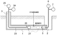
図1は、埋設ガス管の漏洩箇所検査構造の模式図である。
検査対象となる埋設ガス管1は、漏洩ガス管を対象としており、漏洩箇所を特定するため、配管に末端部が2個所ある。
FIG. 1 is a schematic view of a leakage point inspection structure for a buried gas pipe.
The buried
[気密検査ストッパ]
一方の末端部となる口部2には、気密検査ストッパ5が挿入されており、該気密検査ストッパ5には、検査対象となる密封区間内の圧力を検査するため気密検査ストッパ5を通って密封区間を加圧するポンプからなる管内圧力検査加圧ポンプ6と、管内の圧力値を測定する管内圧力検査ゲージ7とが接続されている。
この気密検査ストッパ5の位置は固定しておき、ガス管1内で移動させることはない。
[Airtight inspection stopper]
An
The position of the
[挿入冶具]
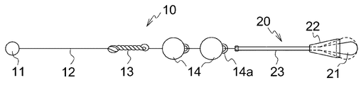
また、前記一方の口部2から、前記気密検査ストッパ5を挿入する前に、予め、図2に示す挿通冶具10とストッパ20とを連結した部材をガス管1内に挿入しておく。
挿通冶具10は、図2に示すように、ピグ11に可撓性を有する線条体の一例として示すワイヤ12を介して、バリ取り具13およびスケール取り具14を連結した構成からなっている。
ここで、挿通冶具10は、上記実施例に限らず、この発明では、ピグ11にワイヤ12を介してバリ取り具13を連結した構成や、ピグ11にワイヤ12を介してスケール取り具14を連結した構成であってもよい(図示せず)。
[Insertion jig]
Further, before inserting the airtightness inspection stopper 5 from the one
As shown in FIG. 2, the
Here, the
[ストッパ]
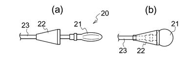
ストッパ20は、図2および図3に示すように、球形や星形などのゴム製バッグ21からなっており、加圧チューブ23に連結しており、該加圧チューブ23により空気加圧するようになっている。
ゴム製バッグ21は、バッグの進行方向に向かって徐々に幅狭となる漏斗状(略円錐形)のゴムを装着した防護ゴム22によってストッパ21の一部をカバーして防護している。
[Stopper]
As shown in FIGS. 2 and 3, the
The
本実施例では、前記加圧チューブ23は10mに設定されており、10m10曲がりに対応することができるようになっているが、長さは一例であり、検査区間に応じて適宜定めることができる。
In the present embodiment, the
図示例の場合、挿入冶具10のスケール取り具14に設けた連結具4aに加圧チューブ23の先端が着脱可能に連結されているが、この着脱構成は図示例に限定されず、係脱や着脱が可能な公知構造を用いて加圧チューブ23が挿通冶具10に連結されていればよい。
In the case of the illustrated example, the distal end of the pressurizing
[挿入冶具]
挿入冶具10は、ワイヤ12の先端にピグ11を連結し、後方にバリ取り具13とスケール取り具14とを間隔を隔てて直列に接続した構成からなっている。
前記ワイヤ12は、本実施例の場合に一例として20m長さからなっている。
[Insertion jig]
The
In the case of the present embodiment, the
[ピグ]
ピグ11は、本実施例では、小さな木玉やスポンジ玉などからなっており、ガス管内を移動することができるもので、他方の口部3からの吸引で引っ張られるものであり、この場合も特に素材や形状は図示例に限定されるものではない。
[Pig]
In this embodiment, the
[バリ取り具]
バリ取り具13は、図4に示すように、ガス管内のバリ取り用の部材であって、本実施例ではワイヤを束ねた構造からなっているが、ガス管末端のバリ取りをすることができるものであれば特に限定されない。
[Deburring tool]
As shown in FIG. 4, the
[スケール取り具]
スケール取り具14は、ガス管内にあるスケールを除去するための部材であって、本実施例では伸縮性のあるゴム玉を2つ用いている。
このスケール取り具14は、通常はガス管の口径より大きいが、管内で収縮することでガス管の内壁面と摩擦しながら通過してスケールを除去する。
この発明でスケール取り具は上記実施例に限定されず、その他のスケールを除去し、これによりストッパ20のシール性の阻害を防止するものであればよい。
[Scale remover]
The
The
In the present invention, the scale removing tool is not limited to the above-described embodiment, and any other scale may be used as long as it removes other scales and thereby prevents the sealing performance of the
[ストッパ圧入ポンプ・ストッパ圧確認ゲージ]
また、埋設ガス管の他方の末端部となる口部3には、前記ストッパ20の加圧チューブ23に接続してストッパを膨出するためのストッパ圧入ポンプ25と、該圧入ポンプ25に分岐して取り付けられてストッパ20の圧力を確認するためのストッパ圧確認ゲージ24とが準備されている。
[Stopper press-fitting pump / stopper pressure check gauge]
Further, a stopper press-fitting
そして、前記挿入冶具10は、他方の口部3から前記ピグ11が吸引されてガス管内を引き出され、このピグ11の移動によりワイヤ12を介してバリ取り具13とスケール取り具14とが牽引されて、ガス管内のバリ取りとスケール取りが行われる。
また、この挿入冶具10には加圧チューブ23の先端が連結されているので、挿入冶具10を他方の口部3から取り出して加圧チューブ23と外し、加圧チューブ23の先端を前記ストッパ圧確認ゲージ24付きのストッパ圧入ポンプ25に接続する(図1参照)。
In the
Further, since the distal end of the
そして、ストッパ20を、前記気密検査ストッパ5から僅かに離れた位置で膨らませてガス管内を密封し、該密封区間内でガスの漏洩があるか否かを気密検査ストッパ5に接続した管内圧力検査ゲージ7により圧力の変化で検査する。
Then, the
圧力の変化が無い場合には、一定の区間だけストッパ20を他方の口部3方向に移動して密封区間を延ばし、同様に検査する。
このように、段階的に順次密封区間を延ばすことで、圧力の減少が検出されると、その直前に検査した区間から現在検査中の密閉区間の間にガスの漏洩個所があることが分かる。
When there is no change in pressure, the
In this way, when a decrease in pressure is detected by extending the sealed section in a stepwise manner, it can be seen that there is a gas leak point between the section immediately inspected and the sealed section currently being inspected.
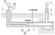
図5は、実施例2の埋設ガス管の漏洩箇所検査構造の模式図である。
この実施例2では、前記実施例1の一方の末端部となる口部2に挿入した気密検査ストッパ5に替えて、配管に設けた立ち管の口部2’のコック4を締めて遮断した構成からなっている。
FIG. 5 is a schematic diagram of a leakage point inspection structure for an embedded gas pipe according to the second embodiment.
In this second embodiment, instead of the
そして、この口部4にはガス管1内の圧力を検査する管内圧力検査ゲージ7’が接続されている。
この実施例2では、一方の口部4がガス栓のコック4で閉められて密封区間の一方となり、他方はストッパ20で閉じられ、密封区間内のガスの圧力は管内圧力検査ゲージ7’によって測定する。
An in-pipe
In the second embodiment, one of the
そして、ストッパ20を他方の口部3方向に段階的に移動させながら、検査区域を延ばしていき、ガスの漏洩個所を特定することができる。
その他の構成は前記実施例と同様であるので同一構成には同一符号を付してその説明を省略する。
その他、要するにこの発明の要旨を変更しない範囲で種々設計変更しうること勿論である。
Then, while moving the
Since other configurations are the same as those of the above-described embodiment, the same components are denoted by the same reference numerals and description thereof is omitted.
In addition, it goes without saying that various design changes can be made without departing from the scope of the present invention.
1 埋設ガス管
2 口部
3 口部
5 気密検査ストッパ
6 管内圧力検査加圧ポンプ
7 管内圧力検査ゲージ
10 挿通冶具
11 ピグ
12 線条体
13 バリ取り具
14 スケール取り具
20 ストッパ
21 ゴム製バッグ
22 防護ゴム
23 加圧チューブ
24 ストッパ圧確認ゲージ
25 ストッパ圧入ポンプ
DESCRIPTION OF
Claims (4)
該一方の口部側に設けられてガス管内の圧力を検査する管内圧力検査ゲージと、
埋設ガス管内に挿入される挿通冶具と、該挿通冶具に着脱可能に連結したストッパ加圧チューブ付きのストッパとからなって、
検査区間の他方の口部から前記挿通冶具を吸引して引っ張り、前記ストッパ加圧チューブを前記挿通冶具から外してストッパ膨出手段に接続してストッパを膨出させて前記気密検査ストッパとの間を密封区間とし、前記ストッパの位置を他方の口部方向へ段階的に移動させて密閉区間を広げながら前記管内圧力検査ゲージでガスの漏洩の有無を検査することを特徴とする埋設ガス管の漏洩箇所検査構造。 Sealing means for sealing one mouth of the inspection section of the buried gas pipe;
An in-pipe pressure inspection gauge that is provided on the one mouth side and inspects the pressure in the gas pipe;
An insertion jig inserted into the buried gas pipe, and a stopper with a stopper pressure tube detachably connected to the insertion jig,
The insertion jig is sucked and pulled from the other mouth of the inspection section, the stopper pressurizing tube is detached from the insertion jig and connected to the stopper bulging means, and the stopper is bulged between the airtight inspection stopper. The embedded gas pipe is characterized by inspecting the presence or absence of gas leakage with the in-pipe pressure test gauge while expanding the sealed section by moving the stopper in a stepwise manner toward the other mouth portion. Leak location inspection structure.
4. The stopper according to claim 1, wherein the stopper includes a substantially spherical bag and a substantially funnel-shaped protective rubber that is externally fitted to a base end side of the bag when the bag is inflated. 5. Leaving point inspection structure for buried gas pipes.
Priority Applications (1)
| Application Number | Priority Date | Filing Date | Title |
|---|---|---|---|
| JP2005347028A JP2007155358A (en) | 2005-11-30 | 2005-11-30 | Leak location inspection structure for buried gas pipe |
Applications Claiming Priority (1)
| Application Number | Priority Date | Filing Date | Title |
|---|---|---|---|
| JP2005347028A JP2007155358A (en) | 2005-11-30 | 2005-11-30 | Leak location inspection structure for buried gas pipe |
Publications (1)
| Publication Number | Publication Date |
|---|---|
| JP2007155358A true JP2007155358A (en) | 2007-06-21 |
Family
ID=38239947
Family Applications (1)
| Application Number | Title | Priority Date | Filing Date |
|---|---|---|---|
| JP2005347028A Pending JP2007155358A (en) | 2005-11-30 | 2005-11-30 | Leak location inspection structure for buried gas pipe |
Country Status (1)
| Country | Link |
|---|---|
| JP (1) | JP2007155358A (en) |
Cited By (4)
| Publication number | Priority date | Publication date | Assignee | Title |
|---|---|---|---|---|
| EP2019546A2 (en) | 2007-06-12 | 2009-01-28 | Nikon Corporation | Digital camera |
| CN104390093A (en) * | 2014-07-26 | 2015-03-04 | 济南城建集团有限公司 | Water closing and air closing test method and used water closing and air closing dual-purpose blockage test airbag |
| CN106768648A (en) * | 2016-12-07 | 2017-05-31 | 大唐东北电力试验研究所有限公司 | Buried pipeline seepage simulation experiment system |
| KR20200090543A (en) * | 2019-01-21 | 2020-07-29 | 주식회사 지앤지테크놀러지 | Leak Check Device and Method for Vertical Closed Ground Heat Exchanger |
-
2005
- 2005-11-30 JP JP2005347028A patent/JP2007155358A/en active Pending
Cited By (7)
| Publication number | Priority date | Publication date | Assignee | Title |
|---|---|---|---|---|
| EP2019546A2 (en) | 2007-06-12 | 2009-01-28 | Nikon Corporation | Digital camera |
| CN104390093A (en) * | 2014-07-26 | 2015-03-04 | 济南城建集团有限公司 | Water closing and air closing test method and used water closing and air closing dual-purpose blockage test airbag |
| CN104390093B (en) * | 2014-07-26 | 2016-03-30 | 济南城建集团有限公司 | Close water, Air-tight Test method and usedly close water, double-purpose shutoff of holding one's breath test air bag |
| CN106768648A (en) * | 2016-12-07 | 2017-05-31 | 大唐东北电力试验研究所有限公司 | Buried pipeline seepage simulation experiment system |
| CN106768648B (en) * | 2016-12-07 | 2023-07-07 | 大唐东北电力试验研究所有限公司 | Buried pipeline leakage simulation test system |
| KR20200090543A (en) * | 2019-01-21 | 2020-07-29 | 주식회사 지앤지테크놀러지 | Leak Check Device and Method for Vertical Closed Ground Heat Exchanger |
| KR102175106B1 (en) * | 2019-01-21 | 2020-11-05 | 주식회사 지앤지테크놀러지 | Leak Check Device and Method for Vertical Closed Ground Heat Exchanger |
Similar Documents
| Publication | Publication Date | Title |
|---|---|---|
| US9249918B2 (en) | Devices and methods for the checking and for the checking and repairing of pipe connections | |
| KR101740514B1 (en) | Defect section detection apparatus for plastic corrugated pipe and defect section detection method using the same | |
| US7331217B2 (en) | Re-usable main drain testing method and apparatus | |
| JP3204588B2 (en) | Sealing device for airtight inspection | |
| JP2007155358A (en) | Leak location inspection structure for buried gas pipe | |
| JP2013024730A (en) | Piping inspection device | |
| US10578511B2 (en) | Flexible universal bladder tool for detecting leaks in a closed fluid system | |
| KR101072609B1 (en) | Apparatus for internal inspection of pipes | |
| JP2003121294A (en) | Gas leaking position detection method and device | |
| JP2008026022A (en) | Water pressure test apparatus for pipe joint and water pressure test method using the same | |
| KR20140131116A (en) | Drain pipe of leak detection devices | |
| JP2000258283A (en) | Method and device for locating leakage point in piping | |
| JP3525005B2 (en) | Leak detection method for existing piping system | |
| JPH0814474A (en) | Sealing device for airtight inspection of pipelines | |
| JP2004271408A (en) | Differential water treatment device and differential water treatment method | |
| CN108663177A (en) | A kind of connector box method for conducting leak test and device | |
| JPH04300500A (en) | In-piping repair and inspection device | |
| CN220104427U (en) | Hose tightness testing device | |
| KR200316305Y1 (en) | Apparatus detecting location of pig for pipeline cleaning | |
| JP2001041400A (en) | Fluid leaking position detecting method | |
| JP4932581B2 (en) | Perforated part sealing method for existing pipes to be lined and perforated part sealing structure | |
| JPH0443798Y2 (en) | ||
| JP3525004B2 (en) | Inspection method of existing piping system | |
| JP2005083910A (en) | Jig for checking leakage | |
| JP3140465U (en) | Internal health survey device |