JP3140465U - Internal health survey device - Google Patents
Internal health survey device Download PDFInfo
- Publication number
- JP3140465U JP3140465U JP2008000119U JP2008000119U JP3140465U JP 3140465 U JP3140465 U JP 3140465U JP 2008000119 U JP2008000119 U JP 2008000119U JP 2008000119 U JP2008000119 U JP 2008000119U JP 3140465 U JP3140465 U JP 3140465U
- Authority
- JP
- Japan
- Prior art keywords
- captured image
- pipe
- internal soundness
- video scope
- monitor
- Prior art date
- Legal status (The legal status is an assumption and is not a legal conclusion. Google has not performed a legal analysis and makes no representation as to the accuracy of the status listed.)
- Expired - Lifetime
Links
Images



Landscapes
- Investigating Materials By The Use Of Optical Means Adapted For Particular Applications (AREA)
Abstract
【課題】 本考案は、古くなった埋設配管の亀裂等の欠陥を検査する内部健全度調査装置に関する。
【解決手段】 ビデオスコープと、このビデオスコープで撮像した撮像画像を処理する処理手段と、上記撮像画像を表示するモニタと、撮像画像を記録する記録手段とを備える内部健全度調査装置であり、この内部健全度調査装置を使用して上記ビデオスコープを配管に挿入し、上記モニタに表示される撮像画像に基づいてコントローラを操作し、配管内の欠陥を検査する内部健全度調査装置である。
【選択図】 図1PROBLEM TO BE SOLVED: To provide an internal soundness investigation device for inspecting a defect such as a crack in an old buried pipe.
An internal soundness investigation device comprising a video scope, processing means for processing a captured image captured by the video scope, a monitor for displaying the captured image, and a recording means for recording the captured image, This internal soundness investigation device is an internal soundness investigation device that inserts the video scope into a pipe using this internal soundness investigation apparatus, operates a controller based on a captured image displayed on the monitor, and inspects defects in the pipe.
[Selection] Figure 1
Description
本考案は、古くなった埋設配管の亀裂、孔食、及び腐食箇所の検査を行う内部健全度調査装置に関する。 The present invention relates to an internal soundness investigation apparatus for inspecting cracks, pitting corrosion, and corrosion points of an old buried pipe.
今日、埋設タンクや地上タンク、縦置き型タンク等の各種タンクが使用されており、これらのタンクと給油口、又は給出口とを配管で接続している。特に配管が地下に埋設されている場合、配管に亀裂、孔食、及び腐食等の欠陥が生じると、配管から油が漏れ出し、問題となる。例えば、ガソリンスタンドで使用される地下タンクにガソリンを注油する場合注油管が使用され、また地下タンクから地上(自動車)に給油する場合給油管が使用されている。 Today, various tanks such as a buried tank, a ground tank, and a vertical tank are used, and these tanks are connected to an oil supply port or a supply outlet with a pipe. In particular, when piping is buried underground, if defects such as cracks, pitting corrosion, and corrosion occur in the piping, oil leaks from the piping, which causes a problem. For example, an oil supply pipe is used when gasoline is injected into an underground tank used at a gas station, and an oil supply pipe is used when oil is supplied from the underground tank to the ground (automobile).
この場合、注油管や給油管は、ほとんど地下に埋設され、古くなると亀裂等が生じ、油漏れの原因になる。このような問題を解決する方法として、例えば特許文献1が提案されている。この考案は、被検査物に超音波を照射して上記被検査物の不連続部を検出する超音波検査方法であり、被検査物の欠陥検査範囲を設定し、一定のピッチで欠陥検査を行う考案である。
しかしながら、上記従来の方法においては、地下に埋設された配管の検査を行うことは困難である。一方、ファイバースコープを使用した各種検査や治療が広く行われている。 However, in the conventional method described above, it is difficult to inspect pipes buried underground. On the other hand, various examinations and treatments using fiberscopes are widely performed.
そこで、本考案は地下に埋設した埋設配管の検査を可能とし、土壌汚染等の原因となる油漏れを防止し、埋設配管の亀裂、孔食、及び腐食を検査する内部健全度調査装置を提供するものであり、特に被検査物の撮像画像を拡大し、また記録し、更に遠隔操作によって遠方から配管欠陥検査を可能とする内部健全度調査装置を提供するものである。 Therefore, the present invention provides an internal soundness inspection device that enables inspection of buried pipes buried underground, prevents oil leakage that causes soil contamination, etc., and inspects buried pipes for cracks, pitting corrosion, and corrosion. In particular, it is an object of the present invention to provide an internal soundness inspection device that enlarges and records a captured image of an object to be inspected, and further enables a pipe defect inspection from a distance by remote control.
上記課題は第1の考案によれば、ビデオスコープと、該ビデオスコープで撮像した撮像画像を処理する処理手段と、前記撮像画像を表示するモニタと、前記撮像画像を記録する記録手段とを有する内部健全度調査装置を提供することによって達成できる。 According to the first aspect of the present invention, there is provided a video scope, a processing unit that processes a captured image captured by the video scope, a monitor that displays the captured image, and a recording unit that records the captured image. This can be achieved by providing an internal health survey device.
また、上記課題は第2の考案によれば、ビデオスコープと、該ビデオスコープで撮像した撮像画像を処理する処理手段と、前記撮像画像を表示するモニタと、前記撮像画像を記録する記録手段とを有する内部健全度調査装置を使用し、前記ビデオスコープを配管に挿入し、前記モニタに表示される撮像画像に基づいてコントローラを操作し、前記配管内の欠陥を検査する内部健全度調査装置を提供することによって達成できる。 According to the second invention, the above-described problem is a video scope, a processing unit that processes a captured image captured by the video scope, a monitor that displays the captured image, and a recording unit that records the captured image. An internal soundness investigation device that inserts the videoscope into a pipe, operates a controller based on a captured image displayed on the monitor, and inspects a defect in the pipe. Can be achieved by providing.
また、上記課題は第3の考案によれば、前記配管は、ガソリンスタンドの注油管、又は給油管であることを特徴とする内部健全度調査装置を提供することによって達成できる。 Moreover, the said subject can be achieved by providing the internal soundness investigation apparatus characterized by the said piping being an oiling pipe or a fueling pipe of a gas station according to 3rd invention.
さらに、上記課題は第4の考案によれば、ネットワークを介してサーバに接続され、前記配管の検査をネットワークを介して遠隔操作によって行う内部健全度調査装置を提供することによって達成できる。 Furthermore, according to the fourth aspect, the above-described problem can be achieved by providing an internal soundness investigation device that is connected to a server via a network and performs an inspection of the pipe by remote operation via the network.
本考案によれば、モニタには撮像画像の拡大表示を行うことができ、また記憶手段に撮像画像の情報を記録することができ、確実に配管に生じた亀裂、孔食、及び腐食等の欠陥を検出することができる。 According to the present invention, an enlarged image of a captured image can be displayed on the monitor, and information of the captured image can be recorded in the storage means, and cracks, pitting corrosion, corrosion, etc. that have occurred in the pipe can be surely detected. Defects can be detected.
以下、本考案の実施の形態を図面を参照しながら説明する。 Hereinafter, embodiments of the present invention will be described with reference to the drawings.
図3は、本考案の内部健全度調査装置の外観図である。同図において、内部健全度調査装置1は光学アダプタを着脱自在に構成したビデオスコープ2と、このビデオスコープ2を収納する本体3と、内部健全度調査装置1の制御を行うコントローラ4と、各種表示を行うモニタ5と、電源供給部6で構成されている。
FIG. 3 is an external view of the internal soundness investigation device of the present invention. In the figure, an internal soundness investigation apparatus 1 includes a
図4は上記内部健全度調査装置1のシステム構成を説明する図である。同図に示すように、内部健全度調査装置1には、制御ユニット7が接続されている。この制御ユニット7は、例えは図3に示した本体3に取り付けられている。
FIG. 4 is a diagram for explaining the system configuration of the internal soundness degree survey device 1. As shown in the figure, a
また、ビデオスコープ2は、撮影時に必要な照明光を得るための光源装置と、ビデオスコープ2を電気的に自在に湾曲させるための湾曲装置を有する。また、ビデオスコープ2の先端の撮像素子からの撮像画像は、本体3内の制御回路に供給される。
In addition, the
本体3の回路構成は、撮像画像処理部8、CPU9、ROM10、RAM11、LANインターフェイス(以下、LANドI/Fで示す)12、USBインターフェイス(以下、USBI/Fで示す)13、入力インターフェイス(以下、入力I/Fで示す)14、マイク入力処理部15、メモリ16、及び操作入力部17で構成されている。
The circuit configuration of the
また、上記入力I/F14には、制御ユニット7、及びバスを介して前述のコントローラ4が接続されている。コントローラ4は、ビデオスコープ2の駆動制御を行う。
The input I / F 14 is connected to the
尚、USBI/F13は、USBメモリを装着し、内部健全度調査装置1によって取得した撮像画像のデータをUSBメモリに記憶する際のインターフェイスである。また、LANドI/F12はパーソナルコンピュータ(PC)を接続する際のインターフェイスである。
The USB I /
撮像画像処理部8は、ビデオスコープ2から供給された撮像画像の処理を行い、モニタ5に表示するために必要な処理を行い、更に処理された撮像画像を信号線を介して前述のUSBメモリに記録する。また、マイク入力処理部15は、マイクにより集音された情報をUSBメモリに記録する為の処理部であり、撮像画像に対応して音声情報をUSBメモリに記録させる構成である。尚、撮像画像、及び音声情報はフラッシュメモリ等で構成されるメモリ16に記録する構成としてもよい。
The captured
尚、CPU9は上記ROM10に記憶されたプログラムに従って処理を行い、RAM11をワークエリアとして使用して内部健全度調査装置1の駆動を行う。また、上記ROM10には予め測定した正常配管(スタンダードサンプル)の画像データが記憶されており、後述する様にスタンダードサンプルの画像データは、測定データとの比較に使用される。また、上記スタンダードサンプルの画像データを上記メモリ16に記憶する構成としてもよい。
The
また、図5は上記ビデオスコープ2の先端部の動きを示す図であり、コントローラ4を使用した操作者の指示によって4方向に湾曲可能な構成である。尚、コントローラ4からの操作信号は操作入力部17、入力I/F14、7ユニット7を介してビデオスコープ2に通知される。
FIG. 5 is a diagram showing the movement of the distal end portion of the
以上の構成において、以下に本例の内部健全度調査装置1を使用して欠陥検査を行う例を説明する。 In the above configuration, an example in which defect inspection is performed using the internal soundness investigation device 1 of this example will be described below.
図1は、本例の内部健全度調査装置1を地下タンクにガソリンを貯蔵する際の配管に適用する例である。同図において、地下タンク21にはガソリンを入れる注油管22、地下タンク21からガソリンを吸引する給油管23、地下タンク21の通気を行う通気管24、及び地下タンク21に貯蔵されたガソリンの液面高を計測する液面計25が設けられている。また、地下タンク21は地表から所定の深さに埋設され、地下タンク21上には不図示のコンクリートが施設されている。
FIG. 1 is an example in which the internal soundness survey device 1 of this example is applied to piping when gasoline is stored in an underground tank. In the figure, an
また、注油管22には地表に注油口26が設けられ、注油口26からガソリンの注油を行う。また、給油管23には地表に計量器、ポンプ等の機器類27が設けられ、地下タンク21からガソリンを吸引し、吸引するガソリンの計量を行う。また、上記注油管22にはバルブ28が設けられ、給油管23にはバルブ29が設けられ、地下タンク21の補修/改修作業の際、このバルブ28及び29を閉鎖して行う。尚、通気管24には通気口30が設けられ、地下タンク21内で発生するガスを排出する。
The
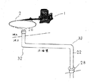
図2は、上述の注油管22の拡大図である。尚、本例では、上記図1に示すようにマンホールは形成されておらず、注油管(埋設配管)22の欠陥検出のためには、上記コンクリートを壊し、穴を掘る必要があった。しかし、本例の場合、以下のようにして注油管22の欠陥を検出する。
FIG. 2 is an enlarged view of the
先ず、ビデオスコープ2による調査前、加圧又は減圧のプレッシャテストを行い、健全度及び異常個所の特定の為に併用する。次に、図2に示すようにビデオスコープ2を注油口26から注油管22内に挿入する。
First, before the investigation by the
その後、作業者は前述のコントローラ4を操作しながら注油管22内の亀裂、孔食、及び腐食を検査する。この場合、ビデオスコープ2の先端には、図5に示すように発光部31が設けられ、注油管22の内部を照明しており、注油管22の内部は前述のモニタ5に映し出されている。したがって、作業者はモニタ5を見ながらコントローラ4を操作し、注油管22内に生じた亀裂、孔食、及び腐食を確認する。
Thereafter, the operator inspects cracks, pitting corrosion, and corrosion in the
この際、前述の図5に示すように、ビデオスコープ2の先端は4方向に湾曲可能であり、作業者はモニタ5を見ながらコントローラ4を操作し、注油管22の注油口26近傍から順次、注油管22の内壁の亀裂等の確認してゆく。尚、注油管22には折曲部32、33を有するが、ビデオスコープ2はフレキシブルに構成されており、注油管22の形状に従って湾曲し、注油管22の終端に設けられたバルブ28の位置まで確実に検査を行うことができる。
At this time, as shown in FIG. 5 described above, the tip of the
またこの間、ビデオスコープ2による撮像画像はモニタ5に順次表示されると共に、前述のUSBメモリにも記録される。したがって、検査終了後において、USBメモリに記録された撮像画像を精査し、微小な亀裂等も確認することができる。
During this time, the images picked up by the
具体的には、前述のようにROM10に予め記憶したスタンダードサンプルと、USBメモリに記録された撮像画像の比較を行い、埋設配管内部の亀裂、孔食、及び腐食箇所を特定する。また、亀裂、又は孔食、又は腐食が発生している場合、埋設配管の入口から発生箇所までの距離、及び大きさを特定する。
また、亀裂、孔食、及び腐食の特定は、埋設年数、周囲環境、経年変化等を考慮して決定する。
Specifically, as described above, the standard sample stored in the
In addition, the identification of cracks, pitting corrosion, and corrosion is determined in consideration of the years of burial, the surrounding environment, aging, and the like.
また、制御ユニット3には撮像画像を拡大する機能も有しており、作業者は必要に応じて注油管22の内壁の拡大画像をモニタ5に表示し、またUSBメモリに記録することができ、更に微小な亀裂等も確認することができる。
The
さらに、マイクを介して作業者は検査対象位置におけるコメント等の音声情報を記録することができ、後に亀裂等を検討する際の参考にすることができる。 Furthermore, the operator can record voice information such as comments at the inspection target position via the microphone, which can be used as a reference when considering cracks and the like later.
一方、図6に示すように、本例の配管欠陥検査装置1がLANI/F13を介してネットワークに接続する例であり、このように構成することにより、本例の配管欠陥検査装置1の出力をネットワークを介してサーバに送信することができる。この場合、例えば撮像画像を専門機関に送信し、亀裂等の検証を行うことも可能となる。
On the other hand, as shown in FIG. 6, the piping defect inspection apparatus 1 of this example is an example of connecting to a network via the LAN I /
さらに、上記ネットワークを使用することによって、作業者自身がビデオスコープ2を遠隔操作し、遠く離れた場所からでも配管検査を行うことが可能となる。
Furthermore, by using the network, the operator can remotely operate the
尚、上記例は注油管22について説明したが、給油管23についても同様に欠陥検査を行うことができる。さらに、ガソリンスタンドの埋設配管に限らず、ガソリン、軽油、重油等を流す埋設配管一般についても、同様に本例の配管欠陥検査装置1によって欠陥検査を行うことができる。
In addition, although the said example demonstrated the oil supply pipe |
1・・・内部健全度調査装置
2・・・ビデオスコープ
3・・・制御ユニット
4・・・コントローラ
5・・・モニタ
6・・・電源供給部
7・・・制御ユニット
8・・・撮像画像処理部
9・・・CPU
10・・ROM
11・・RAM
12・・LANドI/F
13・・USBI/F
14・・入力I/F
15・・マイク入力処理部
16・・メモリ
17・・操作入力部
21・・地下タンク
22・・注油管
23・・給油管
24・・通気管
25・・液面計
26・・注油口
27・・機器類
28、29・・バルブ
30・・通気口
31・・発光部
32、33・・折曲部
DESCRIPTION OF SYMBOLS 1 ... Internal
10. ROM
11. RAM
12. ・ LAN de I / F
13. USB I / F
14. Input I / F
15. · Microphone
Claims (4)
該ビデオスコープで撮像した撮像画像を処理する処理手段と、
前記撮像画像を表示するモニタと、
前記撮像画像を記録する記録手段と、
を有することを特徴とする内部健全度調査装置。 A video scope,
Processing means for processing a captured image captured by the video scope;
A monitor for displaying the captured image;
Recording means for recording the captured image;
An internal soundness investigation device characterized by comprising:
前記ビデオスコープを配管に挿入し、前記モニタに表示される撮像画像に基づいてコントローラを操作し、前記配管内の欠陥を検査することを特徴とする内部健全度調査装置。 An internal soundness investigation device comprising: a video scope; a processing unit that processes a captured image captured by the video scope; a monitor that displays the captured image; and a recording unit that records the captured image;
An internal soundness investigation apparatus, wherein the videoscope is inserted into a pipe, a controller is operated based on a captured image displayed on the monitor, and a defect in the pipe is inspected.
Priority Applications (1)
| Application Number | Priority Date | Filing Date | Title |
|---|---|---|---|
| JP2008000119U JP3140465U (en) | 2008-01-13 | 2008-01-13 | Internal health survey device |
Applications Claiming Priority (1)
| Application Number | Priority Date | Filing Date | Title |
|---|---|---|---|
| JP2008000119U JP3140465U (en) | 2008-01-13 | 2008-01-13 | Internal health survey device |
Publications (1)
| Publication Number | Publication Date |
|---|---|
| JP3140465U true JP3140465U (en) | 2008-03-27 |
Family
ID=43290587
Family Applications (1)
| Application Number | Title | Priority Date | Filing Date |
|---|---|---|---|
| JP2008000119U Expired - Lifetime JP3140465U (en) | 2008-01-13 | 2008-01-13 | Internal health survey device |
Country Status (1)
| Country | Link |
|---|---|
| JP (1) | JP3140465U (en) |
Cited By (1)
| Publication number | Priority date | Publication date | Assignee | Title |
|---|---|---|---|---|
| JP2021110846A (en) * | 2020-01-10 | 2021-08-02 | 株式会社サンフロイント | Internal soundness investigation device for piping |
-
2008
- 2008-01-13 JP JP2008000119U patent/JP3140465U/en not_active Expired - Lifetime
Cited By (2)
| Publication number | Priority date | Publication date | Assignee | Title |
|---|---|---|---|---|
| JP2021110846A (en) * | 2020-01-10 | 2021-08-02 | 株式会社サンフロイント | Internal soundness investigation device for piping |
| JP7441048B2 (en) | 2020-01-10 | 2024-02-29 | 株式会社サンフロイント | Buried piping inspection device |
Similar Documents
| Publication | Publication Date | Title |
|---|---|---|
| US8387461B2 (en) | Inspection method | |
| US7265662B2 (en) | Apparatus and method for inspecting containers | |
| CN104160203B (en) | System and method for checking submarine pipeline | |
| CN108496076A (en) | Integrated system for the hydrogen induced cracking (HIC) in the quantitatively acidic environment of monitoring simulation in real time | |
| CN101676703A (en) | Apparatus for detecting leakage from channel closure plug for fuel channel in heavy water reactor | |
| CN114270181A (en) | Inspection system, determination processing device, and inspection method | |
| JP3140465U (en) | Internal health survey device | |
| JP3159268U (en) | Internal health survey device | |
| TWI592606B (en) | Inside-wall soundness inspection apparatus | |
| KR101815804B1 (en) | Individual Vacuum Consolidation Method‘s Drainage Vacuum Inspection Equipment | |
| KR101357810B1 (en) | capsule check system for check in tube. | |
| JP7441048B2 (en) | Buried piping inspection device | |
| KR20090120138A (en) | Internal health survey device | |
| CN120538582A (en) | Diagnostic method and device for safety of curtain wall concealed engineering | |
| WO2011033677A1 (en) | Defect detecting device | |
| JP2005098894A (en) | Leak detection system for liquid storage tank | |
| GB2531529A (en) | Method for assessing the condition of piping and vessels | |
| CN114078207A (en) | Combustion engine hole peeping inspection component auxiliary identification method based on space coordinate feedback | |
| JP3100913U (en) | Liquid storage tank leak detection device | |
| JP2002005780A (en) | Defect position detecting device for buried pipe | |
| US20210041400A1 (en) | Portable articulating ultrasonic inspection | |
| CN111964602A (en) | Method for detecting deformation of small-diameter underground gas storage well shaft | |
| CN217425822U (en) | Auxiliary device for pipeline of heating surface of industrial endoscope detection header | |
| JP7455046B2 (en) | Underwater inspection equipment and underwater inspection method | |
| JP2007155358A (en) | Leak location inspection structure for buried gas pipe |
Legal Events
| Date | Code | Title | Description |
|---|---|---|---|
| R150 | Certificate of patent or registration of utility model |
Free format text: JAPANESE INTERMEDIATE CODE: R150 |
|
| FPAY | Renewal fee payment (event date is renewal date of database) |
Free format text: PAYMENT UNTIL: 20110305 Year of fee payment: 3 |
|
| FPAY | Renewal fee payment (event date is renewal date of database) |
Free format text: PAYMENT UNTIL: 20120305 Year of fee payment: 4 |
|
| FPAY | Renewal fee payment (event date is renewal date of database) |
Free format text: PAYMENT UNTIL: 20130305 Year of fee payment: 5 |
|
| FPAY | Renewal fee payment (event date is renewal date of database) |
Free format text: PAYMENT UNTIL: 20140305 Year of fee payment: 6 |
|
| R250 | Receipt of annual fees |
Free format text: JAPANESE INTERMEDIATE CODE: R250 |
|
| R250 | Receipt of annual fees |
Free format text: JAPANESE INTERMEDIATE CODE: R250 |
|
| S531 | Written request for registration of change of domicile |
Free format text: JAPANESE INTERMEDIATE CODE: R323531 |
|
| R350 | Written notification of registration of transfer |
Free format text: JAPANESE INTERMEDIATE CODE: R350 |
|
| R250 | Receipt of annual fees |
Free format text: JAPANESE INTERMEDIATE CODE: R250 |
|
| R250 | Receipt of annual fees |
Free format text: JAPANESE INTERMEDIATE CODE: R250 |
|
| EXPY | Cancellation because of completion of term |