JP2007170077A - Muntin roofing construction method - Google Patents
Muntin roofing construction method Download PDFInfo
- Publication number
- JP2007170077A JP2007170077A JP2005370327A JP2005370327A JP2007170077A JP 2007170077 A JP2007170077 A JP 2007170077A JP 2005370327 A JP2005370327 A JP 2005370327A JP 2005370327 A JP2005370327 A JP 2005370327A JP 2007170077 A JP2007170077 A JP 2007170077A
- Authority
- JP
- Japan
- Prior art keywords
- vertical
- roof
- roof tile
- tile
- piece
- Prior art date
- Legal status (The legal status is an assumption and is not a legal conclusion. Google has not performed a legal analysis and makes no representation as to the accuracy of the status listed.)
- Granted
Links
- 238000010276 construction Methods 0.000 title claims abstract description 135
- 238000003780 insertion Methods 0.000 claims abstract description 219
- 230000037431 insertion Effects 0.000 claims abstract description 219
- 230000000087 stabilizing effect Effects 0.000 claims description 121
- 230000006641 stabilisation Effects 0.000 claims description 103
- 238000011105 stabilization Methods 0.000 claims description 103
- 235000014676 Phragmites communis Nutrition 0.000 claims description 56
- 230000000694 effects Effects 0.000 claims description 43
- 210000001217 buttock Anatomy 0.000 claims description 30
- 239000003381 stabilizer Substances 0.000 claims 1
- 238000000034 method Methods 0.000 description 74
- 238000009434 installation Methods 0.000 description 40
- 230000008901 benefit Effects 0.000 description 31
- 238000010586 diagram Methods 0.000 description 10
- 238000006073 displacement reaction Methods 0.000 description 10
- 238000012966 insertion method Methods 0.000 description 10
- XLYOFNOQVPJJNP-UHFFFAOYSA-N water Substances O XLYOFNOQVPJJNP-UHFFFAOYSA-N 0.000 description 10
- 230000002265 prevention Effects 0.000 description 7
- 238000005452 bending Methods 0.000 description 5
- 230000007797 corrosion Effects 0.000 description 5
- 238000005260 corrosion Methods 0.000 description 5
- 238000001035 drying Methods 0.000 description 5
- 238000004519 manufacturing process Methods 0.000 description 5
- 239000000463 material Substances 0.000 description 5
- 230000002195 synergetic effect Effects 0.000 description 5
- 238000009736 wetting Methods 0.000 description 5
- 230000001747 exhibiting effect Effects 0.000 description 4
- 238000000227 grinding Methods 0.000 description 3
- 244000089486 Phragmites australis subsp australis Species 0.000 description 1
- 238000004873 anchoring Methods 0.000 description 1
Images


Landscapes
- Roof Covering Using Slabs Or Stiff Sheets (AREA)
Abstract
Description
本発明は、縦棧葺設工法と、この縦棧葺設工法用の瓦に関する。 The present invention relates to a vertical laying method and a roof tile for the vertical laying method.
従来、この種の縦棧葺設工法及びこれに関連する瓦としては、次のような文献(1)、(2)と(3)が挙げられる。 Conventionally, as this type of vertical construction method and roof tiles related thereto, the following documents (1), (2) and (3) can be cited.
先ず、本出願人の発明である文献(1)と文献(2)を説明すると、この文献(1)は、特開平11−350664号の「安定駒利用の耐震、耐風瓦工法」であり、その概要は、屋根地に地割寸法に沿って縦横棧を付設し、この縦棧に瓦の裏面尻側に設けた安定駒の差込み側の側面を当接して、位置決め(地割寸法に沿って葺設し)するとともに、横棧にこの安定駒の底面を当接し、また横棧に対の引掛けを係止する構成である。また文献(2)は、特開平8−302910号の「瓦の葺設工法」であり、その概要は、屋根地に地割寸法に沿って縦横棧を付設し、この縦棧に瓦の裏面尻側に設けた係止用凸起の棧山側・差込み側の側面、又は切欠段面を当接して、位置決めするとともに、横棧には、従来と同様に、対の引掛けを係止する構成である。 First, the literature (1) and the literature (2), which are the inventions of the present applicant, will be described. This literature (1) is “Anti-seismic and wind-resistant roof tile construction method using a stable piece” of JP-A-11-350664. The outline is that a vertical and horizontal gutter is attached to the roof according to the size of the ground split, and the side of the stability piece provided on the back edge side of the tile is abutted against this vertical gutter for positioning (according to the size of the ground division). In addition, the bottom surface of the stabilizing piece is brought into contact with the recumbent arm and the pair of hooks are engaged with the recumbent arm. Reference (2) is a method for laying roof tiles disclosed in Japanese Patent Application Laid-Open No. 8-302910. The outline of the method is that a vertical and horizontal fence is attached to the roof along the size of the ground, and the back of the tile is attached to the vertical fence. The side surface on the ridge side and the insertion side of the locking protrusion provided on the butt side, or the notch step surface is abutted and positioned, and the pair of hooks is locked on the horizontal surface as in the conventional case. It is a configuration.
そして、この文献(1)と文献(2)の発明は、従来の縦棧工法の特徴である「1」瓦の適確な位置決め、「2」耐震、耐風効果、「3」被せ葺き、差込み葺きの何れにも片寄らない葺設ができる瓦の提供等が図れる。そして、この発明の独特の特徴である「4」縦棧は、所定の隙間(安定駒と瓦裏面との隙間)に挿入可能な構造であれば、その構造を問わないこと及び/又は縦横棧の兼用ができること、「5」縦棧の素材、縦棧の歪み・凹凸・曲がり・寸法等の限定が回避されること等である。 And the inventions of this document (1) and document (2) are the features of the conventional vertical fence method, “1” accurate positioning of the roof tile, “2” earthquake resistance, wind resistance effect, “3” covering, insertion It is possible to provide tiles that can be laid out so as not to be separated from any one of the roofs. The “4” downpipe, which is a unique feature of the present invention, can be inserted into a predetermined gap (the gap between the stable piece and the back of the roof tile), and can be any structure and / or downside down. That can be used together, and “5” downpipe material, downpick distortion, unevenness, bending, dimensions, etc. are avoided.
尚、文献(3)は、特開2000−120223の「瓦」であり、その概要は、瓦の尻側裏面に横棧に係止される引掛け及び縦棧に係止等される係止台と支持台とを膨出形成し、この支持台等と対峙する側に屋根地に接触する安定台を設け、この支持台と安定台を横方向に列設することを特徴とする構成である。その特徴は、従来の縦棧工法の特徴である「1」〜「3」が図れること、また本発明の独特の効果は、「6」縦棧への係止と屋根地に接触する安定台を利用して、瓦を安定的かつ確実に葺設できる。 Reference (3) is “tile” disclosed in Japanese Patent Application Laid-Open No. 2000-120223, and its outline is a hook that is latched on the bottom side of the tile by a horizontal hook and a hook that is locked by a vertical hook. The structure is characterized in that the base and the support base are bulged, a stable base that contacts the roof is provided on the side facing the support base, and the support base and the stable base are arranged side by side. is there. The feature is that “1” to “3”, which are the features of the conventional downpipe method, can be achieved, and the unique effect of the present invention is that the “6” pegs are locked and a stable platform that comes into contact with the roof. The roof tiles can be installed stably and reliably.
前記文献(1)、(2)は、前述の特徴「1」〜「5」を有する優れた発明であるが、その一部に改良の余地が考えられる。例えば、葺設済みの第一の瓦に隣接して第二の瓦を差込み方式で葺設する際に、この第二の瓦の差込み側を、第一の瓦の棧山側裏面と縦棧との間(隙間)に差込む葺設作業が必要であるが、この隙間に差込むには、手間と経験を要する問題があり、この点が改良の余地である。尚、被せ葺きの場合には、葺設済みの第一の瓦の差込み側の上に、第二の瓦の棧山側を被せ葺きする構成であり、前述のような問題は少ない。またこの文献(1)は、安定駒と横棧との係止関係に関する構成は直接意図しないことから、瓦のズレ、飛散又は耐震及び/又は耐風効果に関して、改良すべき点が挙げられる。 The documents (1) and (2) are excellent inventions having the above-mentioned features “1” to “5”, but there is room for improvement in some of them. For example, when the second roof tile is installed adjacent to the first roof tile by the insertion method, the insertion side of the second roof tile is made up of the back surface of the first roof tile and the vertical fence. However, there is a problem that requires labor and experience to insert into this gap, and this is a room for improvement. In addition, in the case of covering, it is the structure which covers the mountain side of the second roof tile on the insertion side of the first roof tile already installed, and there are few problems as described above. Moreover, since this literature (1) does not directly intend the structure related to the locking relationship between the stabilizing piece and the reed, there is a point to be improved regarding the displacement, scattering, earthquake resistance and / or wind resistance effect of the tile.
また文献(3)は、図2において安定駒の尻側に膨出形成した安定台を備えているが、この安定台は、屋根地に接触する構成であり、またこの文献(3)は、横棧を採用しない縦棧専用の瓦であり、得意な構成となっている。従って、本願発明の構成である「イ」の安定駒の尻側端面に設けた凸部を横棧の上面に係止する葺設工法及び/又は瓦とは本質的に相違する。また本願発明の構成である「ロ」の縦横棧を使用した縦棧工法及び/又はその瓦とは、本質的に相違する。さらに本願発明の構成である「ニ」の安定駒の尻側端面に設けた凸部を屋根地に衝止しない構成とし、屋根地の損傷回避と、濡れ防止等を意図する発明とは、本質的に相違する。 Reference (3) is provided with a stabilization base bulging on the bottom side of the stabilization piece in FIG. 2, but this stabilization base is configured to contact the roof, and this reference (3) It is a tile dedicated to vertical fences that do not use firewood, and has a good structure. Therefore, the construction method of the present invention is fundamentally different from the roof construction method and / or roof tile, in which the convex portion provided on the bottom end surface of the stabilizing piece of “I” is locked to the upper surface of the horizontal fence. Further, the vertical rod method using the vertical and horizontal rods of “B” and / or its roof tile, which is the configuration of the present invention, is essentially different. Further, the invention intended for avoiding damage to the roof and preventing wetting, etc., with the convex portion provided on the bottom end face of the stabilizing piece of “D” as the configuration of the present invention being configured not to bump into the roof, is essential. Is different.
請求項1の発明は、第二の瓦(一例である)の差込み側を、第一の瓦(一例である)の棧山側裏面と、縦棧との間に形成した隙間に向かって差込み作業をすることで、この第二の瓦に設けた安定駒の差込み側が、縦棧の側面に添接するとともに、この削面を縦棧の表面に当接すること、またこの安定駒の底面は、横棧の表面に当接される葺設工法であり、この第二の瓦を、容易・確実かつ迅速に差込み葺設すること、又は安定駒の差込み側に、縦棧の側面を衝止して確実に葺設すること、また指による衝止感覚を利用して葺設すること等を意図する。また請求項1の発明は、安定駒の凸部を横棧に係止することで、瓦の安定施工と、ズレ・回転・飛散防止等が図れる差込み葺き工法(差込み葺設する縦棧葺設工法)を提供することを意図する。
In the invention of
請求項1は、屋根地に地割寸法に沿って縦横棧を付設し、一本の縦棧に沿って軒先から棟方向に順次葺設した多数の第一の瓦に隣接して多数の第二の瓦を葺設する縦棧葺設工法であって、
この第二の瓦は、裏面尻側の安定駒から差込み側端面に亘って形成した各種の形状の削面を利用して、前記第一の瓦の棧山側裏面と、縦棧との間に形成した隙間に向かって差込み、この差込み時に、前記縦棧に安定駒の差込み側を添接するとともに、前記削面を前記縦棧に当接し、この添接及び当接時に前記安定駒の底面を前記横棧の表面に当接するとともに、この安定駒の凸部を前記横棧の上面に係止し、当該第二の瓦を縦棧及び/又は横棧を利用して、前記第一の瓦に差込み葺設する縦棧葺設工法である。
The first aspect of the present invention provides a plurality of first tiles adjacent to a number of first tiles which are provided with vertical and horizontal fences along the size of the ground in the roof, and are sequentially installed in the direction of the ridge from the eaves along one vertical fence. A vertical wall construction method for laying a second roof tile,
The second roof tile is formed between the rear surface of the first roof tile and the vertical fence using various shapes of the cut surface formed from the stability piece on the back edge side to the insertion side end face. When inserting, the side of the stable piece is abutted with the downside, and the cutting surface is brought into contact with the downside, and the bottom surface of the stable piece is brought into contact with the side of the side when the abutting and abutting. While abutting on the surface, the convex portion of the stabilizing piece is locked to the upper surface of the recumbent, and the second roof tile is inserted into the first roof tile using a vertical roof and / or a floor spat. It is a vertical dredging construction method.
請求項2の発明は、請求項1の目的を達成できる被せ葺き工法(被せ葺設する縦棧葺設工法)を提供することを意図する。
The invention of
請求項2は、屋根地に地割寸法に沿って縦横棧を付設し、縦棧及び/又は横棧に沿って桁方向に第一の瓦に隣接して第二の瓦を順次葺設する縦棧葺設工法であって、
この第二の瓦の棧山側を、前記第一の瓦の差込み側に被せ葺きするように葺設し、この被せ葺き時に、前記縦棧に前記第一の瓦に設けた安定駒の差込み側を添接するとともに、この第一の瓦に設けた削面を前記縦棧に当接し、この添接及び当接時に前記安定駒の底面を前記横棧の表面に当接するとともに、この安定駒の凸部を前記横棧の上面に係止し、当該第二の瓦を縦棧及び/又は横棧を利用して、前記第一の瓦に被せ葺設する縦棧葺設工法である。
According to the second aspect of the present invention, a vertical and horizontal gutter is attached to the roofing area along the ground division size, and the second tile is sequentially arranged adjacent to the first tile in the girder direction along the vertical gutter and / or the horizontal gutter. A vertical shaft construction method,
The hill side of the second roof tile is installed so as to cover the insertion side of the first roof tile, and at the time of covering, the insertion side of the stabilizing piece provided on the first roof tile is placed on the vertical roof. At the same time, the cutting surface provided on the first roof tile is brought into contact with the vertical fence, and at the time of the attachment and contact, the bottom surface of the stabilization piece is brought into contact with the surface of the horizontal fence, and the convex portion of the stabilization piece is brought into contact with the vertical wall. This is a vertical wall construction method in which the second roof tile is covered with the first roof tile by using a vertical fence and / or a horizontal fence, and is locked to the upper surface of the horizontal fence.
請求項3〜請求項5の発明は、請求項1又は請求項2の目的を達成すること、またこの目的を達成するのに最適な削面の構成を提供することを意図する。
The inventions of
請求項3は、請求項1又は請求項2に記載の削面を、削面の内側より尻側に向かって順次深く形成し、当該第二の瓦を縦棧に当接した際に、この削面の略全部が当該縦棧に接触し、当該第二の瓦の位置決めと、耐震、耐風効果を発揮できる縦棧葺設工法である。 According to a third aspect of the present invention, when the cut surface according to the first or second aspect is formed deeper in order from the inner side of the cut surface toward the buttocks side, the second roof tile is brought into contact with the vertical rod, This is a vertical wall construction method in which almost all of the vertical tiles are in contact with the vertical tiles, and the second roof tile can be positioned, and the seismic and wind resistant effects can be exhibited.
また請求項4は、請求項1又は請求項2に記載の削面を、削面の内側より尻側に向かって同じ深さに形成し、当該第二の瓦を縦棧に当接した際に、この削面の内側が当該縦棧に接触し、当該第二の瓦と縦棧との間に空間が形成されること、また耐震、耐風効果を発揮できる縦棧葺設工法である。
Further, according to
さらに請求項5は、請求項1又は請求項2に記載の削面を、削面の内側より尻側に向かって順次深く形成し、この削面の形状を、瓦を裏面視した際に、三角形状、方形状、又は棧山側に削いだ方形状等の構成としたことを特徴とする耐震、耐風効果を発揮できる縦棧葺設工法である。
Furthermore,
請求項6の発明は、請求項1又は請求項2の目的を達成し、この目的を達成するのに最適な瓦を提供すること、また葺設が容易な縦棧用の瓦を提供すること、さらに凸部の膨出寸法を調整することで、葺設及び/又は結束の確実性と容易性を確保すること等を意図する。さらに安定駒を横棧当接部と横棧係止部とにすみ分け利用することで、その双方の特徴を発揮し、耐震性、飛散防止等の向上と、この安定駒の有効利用を図ることを意図する。そして、必要によりこの凸部は、縦棧への当接面積の拡充を介して前述の総合的な特徴を図ることを意図する。
The invention of claim 6 achieves the object of
請求項6は、請求項1又は請求項2に記載の縦棧葺設工法に使用される瓦であって、
この瓦の裏面の尻側に、当該瓦の谷部の中心を基点として、この差込み側と棧山側とに対の引掛け突起を設け、この差込み側の引掛け突起と、棧山側の引掛け突起とは、屋根地に設けた横棧への略均等な係止を意図して、前記谷部を中心より略同じ所定寸法を確保する構成とし、
またこの瓦の裏面の尻側に、前記差込み側の引掛け突起に隣接して安定駒を形成し、この安定駒から差込み側端面に亘って屋根地に設けた縦棧に当接するための削面を形成し、この削面の内側より尻側に向かって形成される長さが、前記安定駒の流れ方向の長さと略同じにする構成とし、
さらに前記安定駒の尻側に前記横棧に係止する凸部を形成したことを特徴とする縦棧葺設工法用の瓦である。
Claim 6 is a roof tile used for the vertical construction method according to
A pair of hooking projections are provided on the bottom side of the back side of the roof tile, with the center of the valley of the roof of the roof tile as a base point. The projection is intended to be substantially evenly locked to the reed provided on the roof, and has a configuration that ensures substantially the same predetermined dimension from the center of the valley.
Further, on the bottom side of the back of the roof tile, a stable piece is formed adjacent to the hooking protrusion on the insertion side, and a ground surface for contacting a vertical fence provided on the roof from the stable piece to the insertion side end face. And the length formed from the inside of the cut surface toward the butt side is substantially the same as the length in the flow direction of the stabilizing piece,
Furthermore, the roof tile for the vertical wall construction method is characterized in that a convex portion that is locked to the side wall is formed on the bottom side of the stabilizing piece.
請求項7の発明は、請求項6の目的を達成し、この目的を達成するのに最適な瓦を提供すること、また屋根地に損傷を与えないこと、さらに葺設の容易化を図ること等を意図する。
The invention of
請求項7は、請求項6に記載の安定駒の凸部が、屋根地に衝突しない垂下形状としたことを特徴とする縦棧葺設工法用の瓦である。 According to a seventh aspect of the present invention, there is provided a roof tile according to the sixth aspect, wherein the convex portion of the stabilization piece according to the sixth aspect has a hanging shape that does not collide with the roof.
請求項1の発明は、屋根地に地割寸法に沿って縦横棧を付設し、一本の縦棧に沿って軒先から棟方向に順次葺設した多数の第一の瓦に隣接して多数の第二の瓦を葺設する縦棧葺設工法であって、
第二の瓦は、裏面尻側の安定駒から差込み側端面に亘って形成した各種の形状の削面を利用して、第一の瓦の棧山側裏面と、縦棧との間に形成した隙間に向かって差込み、差込み時に、縦棧に安定駒の差込み側を添接するとともに、削面を縦棧に当接し、添接及び当接時に安定駒の底面を横棧の表面に当接するとともに、安定駒の凸部を横棧の上面に係止し、第二の瓦を縦棧及び/又は横棧を利用して、第一の瓦に差込み葺設する縦棧葺設工法である。
In the first aspect of the present invention, a large number of tiles are installed adjacent to a number of first tiles which are provided on the roof with vertical and horizontal fences along the size of the ground, and sequentially installed in the direction of the building from the eaves along one vertical fence. The vertical roof construction method for laying the second tile of
The second roof tile is a gap formed between the back surface of the first roof tile side and the vertical fence using various shapes of cut surfaces formed from the stability piece on the back edge side to the insertion side end face. When inserting, the side of the stable piece is brought into contact with the vertical gutter, and the cutting surface is brought into contact with the vertical gutter. This is a vertical gutter construction method in which a part is locked to the upper surface of a horizontal gutter, and the second tile is inserted into the first tile using a gutter and / or a gutter.
従って、請求項1は、第二の瓦の差込み側を、第一の瓦の棧山側裏面と、縦棧との間に形成した隙間に向かって差込み作業をすることで、この第二の瓦に設けた安定駒の差込み側が、縦棧の側面に添接するとともに、この削面を縦棧の表面に当接できること、またこの安定駒の底面は、横棧の表面に当接される葺設工法であり、この第二の瓦を、容易・確実かつ迅速に差込み葺設できること、又は安定駒の差込み側に、縦棧の側面を衝止して確実に葺設できること、また指による衝止感覚を利用して葺設できること等の特徴を有する。また請求項1は、安定駒の凸部を横棧に係止することで、瓦の安定施工と、ズレ・回転・飛散防止等が図れる差込み葺き工法(差込み葺設する縦棧葺設工法)を提供できること等の実益を有する。 Therefore, according to the first aspect of the present invention, the second tile is inserted by inserting the second tile into the gap formed between the rear surface of the first tile and the vertical fence. The stabilizing piece insertion side provided on the side of the vertical pole is in contact with the side surface of the vertical fence, and the cutting surface can be brought into contact with the surface of the vertical fence. The second roof tile can be inserted and installed easily, reliably and quickly, or the side of the vertical fence can be fixed on the insertion side of the stable piece and can be installed securely. It has the feature that it can be installed. In addition, the first aspect of the present invention provides a method for stable roof tile construction and prevention of misalignment, rotation, scattering, etc. It has real benefits such as being able to provide.
請求項2の発明は、屋根地に地割寸法に沿って縦横棧を付設し、縦棧及び/又は横棧に沿って桁方向に第一の瓦に隣接して第二の瓦を順次葺設する縦棧葺設工法であって、
第二の瓦の棧山側を、第一の瓦の差込み側に被せ葺きするように葺設し、被せ葺き時に、縦棧に第一の瓦に設けた安定駒の差込み側を添接するとともに、第一の瓦に設けた削面を縦棧に当接し、添接及び当接時に安定駒の底面を横棧の表面に当接するとともに、安定駒の凸部を横棧の上面に係止し、第二の瓦を縦棧及び/又は横棧を利用して、第一の瓦に被せ葺設する縦棧葺設工法である。
According to the invention of
The ridge side of the second roof tile is installed so as to cover the insertion side of the first roof tile, and when the cover is mounted, the insertion side of the stabilization piece provided on the first roof tile is attached to the vertical roof, The cutting surface provided on one roof is brought into contact with the vertical shaft, and the bottom surface of the stabilization piece is brought into contact with the surface of the recumbent at the time of attachment and contact, and the convex portion of the stabilization piece is locked to the upper surface of the recumbent surface. This is a vertical installation method in which a tile is covered with a first tile using a vertical fence and / or a horizontal fence.
従って、請求項2は、請求項1の目的を達成できる被せ葺き工法(被せ葺設する縦棧葺設工法)を提供できる特徴を有する。 Accordingly, the second aspect of the present invention has a feature that it is possible to provide a covering method that can achieve the object of the first aspect (a vertical covering method for covering).
請求項3の発明は、請求項1又は請求項2に記載の削面を、削面の内側より尻側に向かって順次深く形成し、第二の瓦を縦棧に当接した際に、削面の略全部が縦棧に接触し、第二の瓦の位置決めと、耐震、耐風効果を発揮できる縦棧葺設工法である。
According to the invention of
また請求項4の発明は、請求項1又は請求項2に記載の削面を、削面の内側より尻側に向かって同じ深さに形成し、第二の瓦を縦棧に当接した際に、削面の内側が縦棧に接触し、第二の瓦と縦棧との間に空間が形成されること、また耐震、耐風効果を発揮できる縦棧葺設工法である。 According to a fourth aspect of the present invention, when the cut surface according to the first or second aspect is formed at the same depth from the inside of the cut surface toward the buttocks side, and the second roof tile is brought into contact with the vertical roof, In this method, the inside of the cut surface is in contact with the vertical fence, a space is formed between the second roof tile and the vertical fence, and a seismic and wind resistant effect can be exhibited.
さらに請求項5の発明は、請求項1又は請求項2に記載の削面を、削面の内側より尻側に向かって順次深く形成し、削面の形状を、瓦を裏面視した際に、三角形状、方形状、又は棧山側に削いだ方形状等の構成とした耐震、耐風効果を発揮できる縦棧葺設工法である。
Further, the invention of
従って、請求項3〜請求項5は、請求項1又は請求項2の目的を達成できること、またこの目的を達成するのに最適な削面の構成を提供できること等の特徴を有する。
Accordingly, claims 3 to 5 have the characteristics that the object of
請求項6の発明は、請求項1又は請求項2に記載の縦棧葺設工法に使用される瓦であって、
瓦の裏面の尻側に、瓦の谷部の中心を基点として、差込み側と棧山側とに対の引掛け突起を設け、差込み側の引掛け突起と、棧山側の引掛け突起とは、屋根地に設けた横棧への略均等な係止を意図して、谷部を中心より略同じ所定寸法を確保する構成とし、
また瓦の裏面の尻側に、差込み側の引掛け突起に隣接して安定駒を形成し、安定駒から差込み側端面に亘って屋根地に設けた縦棧に当接するための削面を形成し、削面の内側より尻側に向かって形成される長さが、安定駒の流れ方向の長さと略同じにする構成とし、
さらに安定駒の尻側に横棧に係止する凸部を形成した縦棧葺設工法用の瓦である。
The invention of claim 6 is a roof tile used for the vertical construction method according to
On the bottom side of the back of the tile, with the center of the valley of the tile as the starting point, a pair of hooking protrusions are provided on the insertion side and the hillside, and the hooking protrusion on the insertion side and the hooking protrusion on the hillside are: With the intention of securing approximately the same predetermined dimension from the center of the valley, with the intention of approximately equal locking to the reeds provided on the roof,
In addition, a stable piece is formed on the rear side of the back side of the roof tile adjacent to the hooking protrusion on the insertion side, and a cut surface is formed to contact a vertical fence provided on the roof from the stability piece to the insertion side end face. The length formed from the inside of the cut surface toward the buttocks side is substantially the same as the length of the stabilizing piece in the flow direction,
Furthermore, it is a roof tile for the vertical construction method in which a convex part that is latched on the side wall is formed on the bottom side of the stability piece.
従って、請求項6は、請求項1又は請求項2の目的を達成できること、この目的を達成するのに最適な瓦を提供できること、また葺設が容易な縦棧用の瓦を提供できること、さらに凸部の膨出寸法を調整することで、葺設及び/又は結束の確実性と容易性を確保できること等の特徴を有する。さらに安定駒を横棧当接部と横棧係止部とにすみ分け利用することで、その双方の特徴を発揮し、耐震性、飛散防止等の向上と、この安定駒の有効利用とが図れる実益がある。そして、必要によりこの凸部は、縦棧への当接面積の拡充を介して前述の総合的な特徴が図れる。
Therefore, claim 6 can achieve the object of
請求項7の発明は、請求項6に記載の安定駒の凸部が、屋根地に衝突しない垂下形状とした縦棧葺設工法用の瓦である。
The invention of
従って、請求項7は、請求項6の目的を達成できること、この目的を達成するのに最適な瓦を提供できること、また屋根地に損傷を与えないこと、さらに葺設の容易化が図れること等の特徴を有する。
Therefore,
以下、本発明の実施の態様(形態)を説明する。 Hereinafter, embodiments (forms) of the present invention will be described.
1は瓦で、この一例では和型瓦を示すが限定されず、例えば、本葺き一体化瓦(本葺き瓦と丸瓦が一体となった簡易型本葺き瓦)、平瓦、S型瓦、平板二山瓦等が含まれる。この瓦1の裏面1−2の尻側1aには、当該瓦1の表面1−1の谷部1−1aの中心を基点として、対の引掛け突起2、3を設ける。この対の引掛け突起2,3は、差込み側1bに設けた引掛け突起2と、棧山側1cに設けた引掛け突起3で構成し、この対の引掛け突起2,3を、屋根地Aに設けた横棧A1に略均等に係止することを意図して、前述の如く、谷部1−1aの中心より略同じ位置に設ける(所定寸法を確保する)ことが望ましいが限定されない。図中1dは瓦1の頭側を示す。
また瓦1の裏面1−2の尻側1aに、差込み側1bの引掛け突起2に隣接して安定駒4を形成し、安定駒4から差込み側1bの端面1b−1に亘って屋根地Aに設けた縦棧A2に当接するための削面5を形成する。この削面5の内側(瓦1の内方)より尻側1a(瓦1の外方)に向かって形成される長さLが、安定駒4の流れ方向(縦棧A2の長手方向「軒から棟の方向」)の長さL1と略同じに構成する。この削面5の望ましい、形態の一例を説明する。図8は、削面5を、裏面視して方形状として、その前後(縦棧A2の長手方向における前後)の角部を縦棧A2に、同図矢印「イ」で図示したような二点支持で添接する。この添接は、縦棧A2との間に、空間を形成して、乾燥、腐蝕防止等に役立てること、又は削面5及び/又は縦棧A2の僅かな形状変化に対しても、使用可能な関係を維持できること等の利点がある。また図9は、削面5を、側面視して尻側1a端面に向かって傾斜形状として、その略全部を同図矢印「ロ」で図示したような縦棧A2に添接する。この添接は、縦棧A2との密着を確保して、葺設の安定性、瓦1の葺設の一定化、安定化等を図ること、又は安定駒4と横棧A1との当接との相乗効果を利用して、前記葺設の安定性、瓦1の葺設の一定化、安定化等に役立てること、さらに耐風性、耐震性の向上に有効であること等の利点がある。さらに図12は、削面5を、裏面視して三角形状として、その前から後に向かった傾斜状の角部を縦棧A2に添接する。この例は、瓦1の製造の容易化、形状の安定性に役立つこと等の利点と、前述の図9に略準ずる利点を有する。
Further, a
そして、また後述する削面5に各態様の凹凸、凹凸条(縦棧A2の長手方向及び/又はその対峙方向等の各方向に向かった、以下省略)、又は係止部等を設けた特徴が発揮できる。尚、この削面5に各態様の凹凸、凹凸条等、又は係止部等を形成し、縦棧A2にこれに対応する各態様の凹凸、凹凸条(縦棧A2の長手方向及び/又はその対峙方向等の各方向に向かった)、又は被係止部等を形成した構造とする。この削面5の各態様の凹凸、凹凸条、又は係止部等と、縦棧A2の各態様の凹凸、凹凸条、又は係止部等との対峙関係を利用し、この両者の係合の容易化、確実化、強固な係合(連繋)等を図ることも可能である。
And the feature which provided the unevenness | corrugation of each aspect, the uneven | corrugated strip (it went to each direction of the longitudinal direction of the vertical rod A2, and / or its opposing direction, it abbreviate | omitted below) or the latching | locking part etc. in the
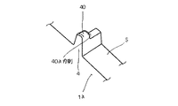
尚、前記安定駒4の長さL1は、瓦1の内側(瓦1の内方)より尻側1a(瓦1の外方)に向かって形成されるが、この安定駒4の長さL1の略1/2に膨出形状の凸部40を形成し、この凸部40の内側40aを横棧A1の上面に係止する構成とし、瓦1の安定葺設と、位置決めの容易化、固定化等に役立てることが好ましい。そして、この凸部40は屋根地Aに衝突しない寸法とする。またこの凸部40を備えた安定駒4は、安定駒4としての本来的な効果を備えるとともに、前述した各種の別の新たな効果及び/又は機能を備えており極めて有効であって、かつ実益性を具備する。また内側40aの略全体を横棧A1の上面に接触する傾斜面(図示せず)とすることも可能である。更に安定駒4の長さL1を延長し、この延長部(図示せず)に係止凸部(図示せず)を設け、前記凸部40とこの係止凸部で横棧A1を挾む構成とし、瓦1の安定葺設と、飛散防止、耐震強度の向上等を図ることも可能である。
The length L1 of the
以下、図3〜図7を基にして、差込み葺きの一例を説明すると、屋根地Aに地割寸法に沿って縦横棧A2、A1を設ける。そして、先ず、第一の瓦100(1)を葺設するに際して、この縦棧A2に第一の瓦100の裏面1−2の尻側1aであって、その差込み側1bに形成した削面5を添接するとともに、この第一の瓦100に設けた安定駒4の差込み側4−1を前記縦棧A2の側面に当接するように葺設し、しかも第一の瓦100に設けた安定駒4の凸部40の尻側端部を横棧A2に係止する。この一連の葺設作業で、第一の瓦100が縦横棧A2、A1を利用して屋根地Aに葺設される。続いて、第二の瓦101(1)を葺設するに際し、この第二の瓦101を、前記第一の瓦100の棧山側1cの裏面1−2と、縦棧A2との間に形成した隙間Hに向かって、当該第二の瓦101の差込み側1bを差込み、しかもこの第二の瓦101の裏面1−2に設けた削面5を、縦棧A2に添接するようにして差込むとともに、この第二の瓦101の安定駒4の凸部40を横棧A1に係止する。この一連の葺設作業で、第二の瓦101が縦横棧A2、A1を利用して屋根地Aに葺設される。以上のような葺設作業を順次行うことで、この屋根地Aの全体に瓦1が葺設される。
Hereinafter, based on FIGS. 3 to 7, a description will be given of an example of the insertion method. The roof A is provided with the vertical and horizontal planes A <b> 2 and A <b> 1 along the ground division size. First, when laying the first roof tile 100 (1), the vertical surface A2 is the bottom surface 1a of the back surface 1-2 of the
また他の差込み葺きとしては、前述の第一の瓦100を順次屋根地Aの軒先Bから棟B1方向に向かって葺設し、この第一の瓦100に隣接する第二の瓦101を差込み葺設する方法もある。この場合は、前述と同様にこの第一の瓦100に第二の瓦101を同様に差込み葺きする。そして、この第二の瓦101を同様に順次屋根地Aの軒先Bから棟B1方向に向かって葺設する。以上のような葺設作業を順次行うことで、この屋根地Aの全体に瓦1が葺設される。
As another insertion, the above-described
従って、第一の瓦100、第二の瓦101(総称する場合は瓦1とする)を、容易・確実かつ迅速に差込み葺設できること、又は安定駒4の差込み側4−1を縦棧A2の側面に衝止及び/又は削面5を縦棧A2の表面に添接し、かつ安定駒4の凸部40を横棧A1の上面(尻側端部)に係止できることから、瓦1を確実かつ安定して葺設できること、また葺設の簡便化、迅速化等に役立つこと、さらに指による衝止感覚を利用して葺設できること等の特徴を有する。また図示しないが、葺き替えの場合にも、前述と同様な手段が採用できる。従って、この葺き替えの簡便化、迅速化等に役立つ特徴を有する。また従来の縦棧工法では、極めて困難であった、この種の葺き替え作業が容易にできる実益がある。
Therefore, the
尚、瓦1の被せ葺きの場合は、図示しないが、前述と同様に第一の瓦100の裏面1−2に設けた削面5を、縦棧A2に添接するとともに、この第一の瓦100の安定駒4の凸部40を横棧A1に係止する。続いて、この第一の瓦100の差込み側1bに第二の瓦101の棧山側1cを被せ葺きする。この際に前述と同様に、この第二の瓦101の裏面1−2に設けた削面5を、縦棧A2に添接するとともに、この第二の瓦101の安定駒4の凸部40を横棧A1に係止する。この一連の葺設作業で、第一の瓦100及び第二の瓦101が縦横棧A2、A1を利用して屋根地Aに葺設される。以上のような葺設作業を順次行うことで、この屋根地Aの全体に瓦1が葺設される。従って、前述の差込み葺きと同様な効果が期待できる。
In the case of covering the
図中20は尻棧山側の切込み、21は頭差込み側の切込みをそれぞれ示す。また22は釘穴、23は水返しを示す。
In the figure, 20 indicates a cut on the buttock mountain side, and 21 indicates a cut on the head insertion side.
1 瓦
100 第一の瓦
101 第二の瓦
1−1 表面
1−1a 谷部
1−2 裏面
1a 尻側
1b 差込み側
1b−1 端面
1c 棧山側
1d 頭側
2 引掛け突起
3 引掛け突起
4 安定駒
4−1 差込み側
40 凸部
40a 内側
5 削面
20 切込み
21 切込み
22 釘穴
23 水返し
A 屋根地
A1 横棧
A2 縦棧
B 軒先
B1 棟
H 隙間
L 長さ
L1 長さ
DESCRIPTION OF
本発明は、縦棧葺設工法に関する。 The present invention relates to a vertical anchor construction method .
従来、この種の縦棧葺設工法としては、次のような文献(1)、(2)と(3)が挙げられる。 Conventionally, as this type of vertical construction method, there are the following documents (1), (2) and (3).
先ず、本出願人の発明である文献(1)と文献(2)を説明すると、この文献(1)は、特開平11−350664号の「安定駒利用の耐震、耐風瓦工法」であり、その概要は、屋根地に地割寸法に沿って縦横棧を付設し、この縦棧に瓦の裏面尻側に設けた安定駒の差込み側の側面を当接して、位置決め(地割寸法に沿って葺設し)するとともに、横棧にこの安定駒の底面を当接し、また横棧に対の引掛けを係止する構成である。また文献(2)は、特開平8−302910号の「瓦の葺設工法」であり、その概要は、屋根地に地割寸法に沿って縦横棧を付設し、この縦棧に瓦の裏面尻側に設けた係止用凸起の棧山側・差込み側の側面、又は切欠段面を当接して、位置決めするとともに、横棧には、従来と同様に、対の引掛けを係止する構成である。 First, the literature (1) and the literature (2), which are the inventions of the present applicant, will be described. This literature (1) is “Anti-seismic and wind-resistant roof tile construction method using a stable piece” of JP-A-11-350664. The outline is that a vertical and horizontal gutter is attached to the roof according to the size of the ground split, and the side of the stability piece provided on the back edge side of the tile is abutted against this vertical gutter for positioning (according to the size of the ground division). In addition, the bottom surface of the stabilizing piece is brought into contact with the recumbent arm and the pair of hooks are engaged with the recumbent arm. Reference (2) is a method for laying roof tiles disclosed in Japanese Patent Application Laid-Open No. 8-302910. The outline of the method is that a vertical and horizontal fence is attached to the roof along the size of the ground, and the back of the tile is attached to the vertical fence. The side surface on the ridge side and the insertion side of the locking protrusion provided on the butt side, or the notch step surface is abutted and positioned, and the pair of hooks is locked on the horizontal surface as in the conventional case. It is a configuration.
そして、この文献(1)と文献(2)の発明は、従来の縦棧工法の特徴である「1」瓦の適確な位置決め、「2」耐震、耐風効果、「3」被せ葺き、差込み葺きの何れにも片寄らない葺設ができる瓦の提供等が図れる。そして、この発明の独特の特徴である「4」縦棧は、所定の隙間(安定駒と瓦裏面との隙間)に挿入可能な構造であれば、その構造を問わないこと及び/又は縦横棧の兼用ができること、「5」縦棧の素材、縦棧の歪み・凹凸・曲がり・寸法等の限定が回避されること等である。 And the inventions of this document (1) and document (2) are the features of the conventional vertical fence method, “1” accurate positioning of the roof tile, “2” earthquake resistance, wind resistance effect, “3” covering, insertion It is possible to provide tiles that can be laid out so as not to be separated from any one of the roofs. The “4” downpipe, which is a unique feature of the present invention, can be inserted into a predetermined gap (the gap between the stable piece and the back of the roof tile), and can be any structure and / or downside down. That can be used together, and “5” downpipe material, downpick distortion, unevenness, bending, dimensions, etc. are avoided.
尚、文献(3)は、特開2000−120223の「瓦」であり、その概要は、瓦の尻側裏面に横棧に係止される引掛け及び縦棧に係止等される係止台と支持台とを膨出形成し、この支持台等と対峙する側に屋根地に接触する安定台を設け、この支持台と安定台を横方向に列設することを特徴とする構成である。その特徴は、従来の縦棧工法の特徴である「1」〜「3」が図れること、また本発明の独特の効果は、「6」縦棧への係止と屋根地に接触する安定台を利用して、瓦を安定的かつ確実に葺設できる。 Reference (3) is “tile” disclosed in Japanese Patent Application Laid-Open No. 2000-120223, and its outline is a hook that is latched on the bottom side of the tile by a horizontal hook and a hook that is locked by a vertical hook. The structure is characterized in that the base and the support base are bulged, a stable base that contacts the roof is provided on the side facing the support base, and the support base and the stable base are arranged side by side. is there. The feature is that “1” to “3”, which are the features of the conventional downpipe method, can be achieved, and the unique effect of the present invention is that the “6” pegs are locked and a stable platform that comes into contact with the roof. The roof tiles can be installed stably and reliably.
前記文献(1)、(2)は、前述の特徴「1」〜「5」を有する優れた発明であるが、その一部に改良の余地が考えられる。例えば、葺設済みの第一の瓦に隣接して第二の瓦を差込み方式で葺設する際に、この第二の瓦の差込み側を、第一の瓦の棧山側裏面と縦棧との間(隙間)に差込む葺設作業が必要であるが、この隙間に差込むには、手間と経験を要する問題があり、この点が改良の余地である。尚、被せ葺きの場合には、葺設済みの第一の瓦の差込み側の上に、第二の瓦の棧山側を被せ葺きする構成であり、前述のような問題は少ない。またこの文献(1)は、安定駒と横棧との係止関係に関する構成は直接意図しないことから、瓦のズレ、飛散又は耐震及び/又は耐風効果に関して、改良すべき点が挙げられる。 The documents (1) and (2) are excellent inventions having the above-mentioned features “1” to “5”, but there is room for improvement in some of them. For example, when the second roof tile is installed adjacent to the first roof tile by the insertion method, the insertion side of the second roof tile is made up of the back surface of the first roof tile and the vertical fence. However, there is a problem that requires labor and experience to insert into this gap, and this is a room for improvement. In addition, in the case of covering, it is the structure which covers the mountain side of the second roof tile on the insertion side of the first roof tile already installed, and there are few problems as described above. Moreover, since this literature (1) does not directly intend the structure related to the locking relationship between the stabilizing piece and the reed, there is a point to be improved regarding the displacement, scattering, earthquake resistance and / or wind resistance effect of the tile.
また文献(3)は、図2において安定駒の尻側に膨出形成した安定台を備えているが、この安定台は、屋根地に接触する構成であり、またこの文献(3)は、横棧を採用しない縦棧専用の瓦であり、得意な構成となっている。従って、本願発明の構成である「イ」の安定駒の尻側端面に設けた凸部を横棧の上面に係止する葺設工法及び/又は瓦とは本質的に相違する。また本願発明の構成である「ロ」の縦横棧を使用した縦棧工法及び/又はその瓦とは、本質的に相違する。さらに本願発明の構成である「ニ」の安定駒の尻側端面に設けた凸部を屋根地に衝止しない構成とし、屋根地の損傷回避と、濡れ防止等を意図する発明とは、本質的に相違する。 Reference (3) is provided with a stabilization base bulging on the bottom side of the stabilization piece in FIG. 2, but this stabilization base is configured to contact the roof, and this reference (3) It is a tile dedicated to vertical fences that do not use firewood, and has a good structure. Therefore, the construction method of the present invention is fundamentally different from the roof construction method and / or roof tile, in which the convex portion provided on the bottom end surface of the stabilizing piece of “I” is locked to the upper surface of the horizontal fence. Further, the vertical rod method using the vertical and horizontal rods of “B” and / or its roof tile, which is the configuration of the present invention, is essentially different. Further, the invention intended for avoiding damage to the roof and preventing wetting, etc., with the convex portion provided on the bottom end face of the stabilizing piece of “D” as the configuration of the present invention being configured not to bump into the roof, is essential. Is different.
請求項1の発明は、第二の瓦(一例である)の差込み側を、第一の瓦(一例である)の棧山側裏面と、縦棧との間に形成した隙間に向かって差込み作業をすることで、この第二の瓦に設けた安定駒の差込み側が、縦棧の側面に添接するとともに、この削面を縦棧の表面に当接すること、またこの安定駒の底面は、横棧の表面に当接される葺設工法であり、この第二の瓦を、容易・確実かつ迅速に差込み葺設すること、又は安定駒の差込み側に、縦棧の側面を衝止して確実に葺設すること、また指による衝止感覚を利用して葺設すること等を意図する。また請求項1の発明は、安定駒の凸部を横棧に係止することで、瓦の安定施工と、ズレ・回転・飛散防止等が図れる差込み葺き工法(差込み葺設する縦棧葺設工法)を提供することを意図する。
In the invention of
請求項1は、屋根地に地割に沿って縦横棧を付設し、一本の縦棧に沿って軒先から棟方向に第一の瓦を順次葺設するに際して、この縦棧に安定駒の差込み側を添接し、またこの縦棧に削面を当接するとともに、この第一の瓦の添接及び当接時に、この第一の瓦の安定駒の底面を、前記横棧の表面に当接し、かつこの安定駒に設けた屋根地に衝突しない寸法の凸部と引掛け突起を前記横棧に係止し、この葺設した多数の第一の瓦に隣接して、多数の第二の瓦を葺設する縦棧葺設工法であって、
この第二の瓦は、裏面尻側の凸部を備えた安定駒から差込み側端面に亘って形成した削面を利用して、前記第一の瓦の棧山側裏面と、縦棧との間に形成した隙間に向かって差込み、この差込み時に、前記縦棧に安定駒の差込み側を添接し、また前記削面を前記縦棧に当接するとともに、この第二の瓦の添接及び当接時に、この第二の瓦の安定駒の底面を前記横棧の表面に当接し、かつこの安定駒に設けた屋根地に衝突しない寸法の凸部と引掛け突起を前記横棧に係止し、当該第二の瓦を縦棧及び横棧を利用して、前記第一の瓦に差込み葺設する縦棧葺設工法である。
The first aspect of the present invention is that, when a vertical and horizontal gutter is attached to the roofing area along the ground division, and the first tile is laid in sequence from the eaves to the ridge along the vertical gutter, the stabilization piece is inserted into the vertical gutter. Abutting the side, and abutting the cutting surface against the vertical fence, and when the first tile is attached and abutted, the bottom surface of the stabilizing piece of the first tile is brought into contact with the surface of the horizontal fence, and The convex part and the hooking projection of the size which do not collide with the roof provided in this stabilization piece are locked to the above-mentioned horizontal fence, and a large number of second tiles are adjacent to the numerous first roof tiles. A vertical dredging construction method,
This second roof tile is formed between a stability piece provided with a convex portion on the back edge side and a cutting surface formed from the insertion side end face, between the back surface on the mountain side of the first roof tile and the vertical fence. Inserted toward the formed gap, and at the time of this insertion, the insertion side of the stable piece is attached to the downside, and the cut surface is brought into contact with the downside, and at the time of attachment and contact of the second roof tile, the bottom surface of the stabilizing piece of the second tile contacts the surface of the transverse rung and lock the projection and the hooking protrusion dimensions that do not collide with the roof locations, provided the stabilizing piece to said transverse rung, the second the tiles utilizing Tate棧and Yoko棧 a vertical棧葺設工method of inserting葺設to the first tile.
請求項2の発明は、請求項1の目的を達成できる被せ葺き工法(被せ葺設する縦棧葺設工法)を提供することを意図する。
The invention of
請求項2は、屋根地に地割に沿って縦横棧を付設し、縦棧及び横棧に沿って桁方向に第一の瓦を順次葺設するに際して、この縦棧に安定駒の差込み側を添接し、またこの縦棧に削面を当接するとともに、この第一の瓦の添接及び当接時に、この第一の瓦の安定駒の底面を、前記横棧の表面に当接し、かつこの安定駒に設けた屋根地に衝突しない寸法の凸部と引掛け突起を前記横棧に係止し、この葺設した第一の瓦に隣接して、第二の瓦を葺設する縦棧葺設工法であって、
この第二の瓦の棧山側を、前記第一の瓦の差込み側に被せ葺きするように葺設し、この被せ葺き時に、前記縦棧にこの第二の瓦に設けた安定駒の差込み側を添接し、当該第二の瓦に設けた削面を前記縦棧に当接し、かつこの第二の瓦の添接及び当接時に、この安定駒の底面を前記横棧の表面に当接し、かつこの第二の瓦の安定駒に設けた屋根地に衝突しない寸法の凸部と引掛け突起を前記横棧に係止し、当該第二の瓦を縦棧及び横棧を利用して、前記第一の瓦に被せ葺設する縦棧葺設工法である。
According to
The hill side of the second roof tile is installed so as to cover the insertion side of the first roof tile, and when this cover is mounted, the insertion side of the stabilizing piece provided on the second roof tile is placed on the vertical roof. Abutting, the cutting surface provided on the second roof tile is in contact with the vertical fence , and when the second roof tile is in contact with and contacting, the bottom surface of the stabilization piece is in contact with the surface of the horizontal fence; and The convex part and the hooking protrusion of the size which do not collide with the roof ground provided in the stabilization piece of the second tile are locked to the recumbent , and the second tile is utilized using the vertical reed and recumbent , This is a vertical installation method that covers the first roof tile.
請求項3〜請求項5の発明は、請求項1又は請求項2の目的を達成すること、またこの目的を達成するのに最適な削面の構成を提供することを意図する。
The inventions of
請求項3は、請求項1又は請求項2に記載の縦棧葺設工法において、削面を、この削面の内側より尻側に向かって順次深く形成し、当該第二の瓦を縦棧に当接した際に、この削面の略全部が当該縦棧に接触し、当該第二の瓦の位置決めと、耐震、耐風効果を発揮できる縦棧葺設工法である。 According to a third aspect of the present invention, in the vertical dredge construction method according to the first or second aspect, the cut surface is formed in order deeper from the inside of the cut surface toward the buttocks side, and the second roof tile is applied to the vertical rod. This is a vertical dredging construction method in which almost all of the cut surface comes into contact with the vertical raft when in contact, and the second roof tile can be positioned, and the seismic and wind resistant effects can be exhibited.
また請求項4は、請求項1又は請求項2に記載の縦棧葺設工法において、削面を、この削面の内側より尻側に向かって同じ深さに形成し、当該第二の瓦を縦棧に当接した際に、この削面の内側が当該縦棧に接触し、当該第二の瓦と縦棧との間に空間が形成されること、また耐震、耐風効果を発揮できる縦棧葺設工法である。 According to a fourth aspect of the present invention, in the vertical rod construction method according to the first or second aspect, the cut surface is formed to have the same depth from the inside of the cut surface toward the buttocks side, and the second roof tile is formed vertically. When the abutment comes into contact with the saddle, the inside of the cut surface comes into contact with the vertical fence, and a space is formed between the second roof tile and the vertical fence. Construction method.
さらに請求項5は、請求項1又は請求項2に記載の縦棧葺設工法において、削面を、この削面の内側より尻側に向かって順次深く形成し、この削面の形状は、この瓦を裏面視した際に、三角形状、方形状の構成としたことを特徴とする耐震、耐風効果を発揮できる縦棧葺設工法である。
Furthermore,
請求項1の発明は、屋根地に地割に沿って縦横棧を付設し、一本の縦棧に沿って軒先から棟方向に第一の瓦を順次葺設するに際して、縦棧に安定駒の差込み側を添接し、また縦棧に削面を当接するとともに、第一の瓦の添接及び当接時に、第一の瓦の安定駒の底面を、横棧の表面に当接し、かつ安定駒に設けた屋根地に衝突しない寸法の凸部と引掛け突起を横棧に係止し、葺設した多数の第一の瓦に隣接して、多数の第二の瓦を葺設する縦棧葺設工法であって、
第二の瓦は、裏面尻側の凸部を備えた安定駒から差込み側端面に亘って形成した削面を利用して、第一の瓦の棧山側裏面と、縦棧との間に形成した隙間に向かって差込み、差込み時に、縦棧に安定駒の差込み側を添接し、また削面を縦棧に当接するとともに、第二の瓦の添接及び当接時に、第二の瓦の安定駒の底面を横棧の表面に当接し、かつ安定駒に設けた屋根地に衝突しない寸法の凸部と引掛け突起を横棧に係止し、第二の瓦を縦棧及び横棧を利用して、第一の瓦に差込み葺設する縦棧葺設工法である。
According to the first aspect of the present invention, when a vertical and horizontal gutter is attached to the roofing area along the ground division, and the first tile is erected sequentially from the eaves to the ridge along the vertical gutter, Attaching the insertion side and abutting the cut surface to the vertical fence, and at the time of attachment and abutment of the first roof tile, the bottom face of the stable roof of the first roof tile contacts the surface of the horizontal fence and A vertical gutter that has a number of second roof tiles installed adjacent to a number of first roof tiles that are latched on the side with projections and hooking projections that do not collide with the provided roofing area. Construction method,
The second roof tile was formed between the rear surface of the first roof tile and the vertical fence using a shaving surface formed from the stabilizing piece having the convex part on the back side to the insertion side end face. Inserted toward the gap, and when inserted, the side of the stable piece is attached to the vertical gutter, and the cutting surface is brought into contact with the vertical gutter. Abutment with the surface of the recumbent surface , and the convex part and the hooking protrusion of the dimension that do not collide with the roof provided on the stabilization piece are engaged with the recumbent, and the second roof tile is used with the reed and recumbent This is a vertical construction method in which the first roof tile is inserted and installed.
従って、請求項1は、第二の瓦の差込み側を、第一の瓦の棧山側裏面と、縦棧との間に形成した隙間に向かって差込み作業をすることで、この第二の瓦に設けた安定駒の差込み側が、縦棧の側面に添接するとともに、この削面を縦棧の表面に当接できること、またこの安定駒の底面は、横棧の表面に当接される葺設工法であり、この第二の瓦を、容易・確実かつ迅速に差込み葺設できること、又は安定駒の差込み側に、縦棧の側面を衝止して確実に葺設できること、また指による衝止感覚を利用して葺設できること等の特徴を有する。また請求項1は、安定駒の凸部を横棧に係止することで、瓦の安定施工と、ズレ・回転・飛散防止等が図れる差込み葺き工法(差込み葺設する縦棧葺設工法)を提供できること等の実益を有する。 Therefore, according to the first aspect of the present invention, the second tile is inserted by inserting the second tile into the gap formed between the rear surface of the first tile and the vertical fence. The stabilizing piece insertion side provided on the side of the vertical pole is in contact with the side surface of the vertical fence, and the cutting surface can be brought into contact with the surface of the vertical fence. The second roof tile can be inserted and installed easily, reliably and quickly, or the side of the vertical fence can be fixed on the insertion side of the stable piece and can be installed securely. It has the feature that it can be installed. In addition, the first aspect of the present invention provides a method for stable roof tile construction and prevention of misalignment, rotation, scattering, etc. It has real benefits such as being able to provide.
請求項2の発明は、屋根地に地割に沿って縦横棧を付設し、縦棧及び横棧に沿って桁方向に第一の瓦を順次葺設するに際して、縦棧に安定駒の差込み側を添接し、また縦棧に削面を当接するとともに、第一の瓦の添接及び当接時に、第一の瓦の安定駒の底面を、横棧の表面に当接し、かつ安定駒に設けた屋根地に衝突しない寸法の凸部と引掛け突起を横棧に係止し、葺設した第一の瓦に隣接して、第二の瓦を葺設する縦棧葺設工法であって、
第二の瓦の棧山側を、第一の瓦の差込み側に被せ葺きするように葺設し、被せ葺き時に、縦棧に第二の瓦に設けた安定駒の差込み側を添接し、第二の瓦に設けた削面を縦棧に当接し、かつ第二の瓦の添接及び当接時に、安定駒の底面を横棧の表面に当接し、かつ第二の瓦の安定駒に設けた屋根地に衝突しない寸法の凸部と引掛け突起を横棧に係止し、第二の瓦を縦棧及び横棧を利用して、第一の瓦に被せ葺設する縦棧葺設工法である。
The invention of
The棧山side of the second tile, and葺設as roofing over the insertion side of the first tile, when roofing cover, and bears against the plug side of the stable piece provided on the second tile to Tate棧, the The cutting surface provided on the second tile is in contact with the vertical tile, and when the second tile is attached and contacted, the bottom surface of the stabilization piece is in contact with the surface of the horizontal fence and provided on the stabilization piece of the second tile. Longitudinal construction method in which convex parts and hooking projections with dimensions that do not collide with the roofing land are latched on the side, and the second roof tile is covered with the first roof tile using the vertical and side hooks. It is.
従って、請求項2は、請求項1の目的を達成できる被せ葺き工法(被せ葺設する縦棧葺設工法)を提供できる特徴を有する。 Accordingly, the second aspect of the present invention has a feature that it is possible to provide a covering method that can achieve the object of the first aspect (a vertical covering method for covering).
請求項3の発明は、請求項1又は請求項2に記載の縦棧葺設工法において、削面を、削面の内側より尻側に向かって順次深く形成し、第二の瓦を縦棧に当接した際に、削面の略全部が縦棧に接触し、第二の瓦の位置決めと、耐震、耐風効果を発揮できる縦棧葺設工法である。 According to a third aspect of the present invention, in the vertical rod construction method according to the first or second aspect , the cut surface is formed deeper in order from the inner side of the cut surface to the buttocks side, and the second roof tile is applied to the vertical rod. This is a vertical dredge construction method in which almost all of the cut surface comes into contact with the vertical raft when it comes into contact, and the positioning of the second roof tile, earthquake resistance, and wind resistance can be exhibited.
また請求項4の発明は、請求項1又は請求項2に記載の縦棧葺設工法において、削面を、削面の内側より尻側に向かって同じ深さに形成し、第二の瓦を縦棧に当接した際に、削面の内側が縦棧に接触し、第二の瓦と縦棧との間に空間が形成されること、また耐震、耐風効果を発揮できる縦棧葺設工法である。 According to a fourth aspect of the present invention, in the vertical anchoring method according to the first or second aspect , the cut surface is formed at the same depth from the inside of the cut surface toward the buttocks side, and the second roof tile is formed vertically. When contacting the reed, the inside of the cut surface comes into contact with the reed, and a space is formed between the second roof tile and the reed, and a vertical reed construction method that can exhibit earthquake and wind resistance effects. is there.
さらに請求項5の発明は、請求項1又は請求項2に記載の縦棧葺設工法において、削面を、削面の内側より尻側に向かって順次深く形成し、削面の形状は、瓦を裏面視した際に、三角形状、方形状の構成としたことを特徴とする耐震、耐風効果を発揮できる縦棧葺設工法である。
Further, the invention of
従って、請求項3〜請求項5は、請求項1又は請求項2の目的を達成できること、またこの目的を達成するのに最適な削面の構成を提供できること等の特徴を有する。
Accordingly, claims 3 to 5 have the characteristics that the object of
以下、本発明の実施の態様(形態)を説明する。 Hereinafter, embodiments (forms) of the present invention will be described.
1は瓦で、この一例では和型瓦を示すが限定されず、例えば、本葺き一体化瓦(本葺き瓦と丸瓦が一体となった簡易型本葺き瓦)、平瓦、S型瓦、平板二山瓦等が含まれる。この瓦1の裏面1−2の尻側1aには、当該瓦1の表面1−1の谷部1−1aの中心を基点として、対の引掛け突起2、3を設ける。この対の引掛け突起2,3は、差込み側1bに設けた引掛け突起2と、棧山側1cに設けた引掛け突起3で構成し、この対の引掛け突起2,3を、屋根地Aに設けた横棧A1に略均等に係止することを意図して、前述の如く、谷部1−1aの中心より略同じ位置に設ける(所定寸法を確保する)ことが望ましいが限定されない。図中1dは瓦1の頭側を示す。
また瓦1の裏面1−2の尻側1aに、差込み側1bの引掛け突起2に隣接して安定駒4を形成し、安定駒4から差込み側1bの端面1b−1に亘って屋根地Aに設けた縦棧A2に当接するための削面5を形成する。この削面5の内側(瓦1の内方)より尻側1a(瓦1の外方)に向かって形成される長さLが、安定駒4の流れ方向(縦棧A2の長手方向「軒から棟の方向」)の長さL1と略同じに構成する。この削面5の望ましい、形態の一例を説明する。図8は、削面5を、裏面視して方形状として、その前後(縦棧A2の長手方向における前後)の角部を縦棧A2に、同図矢印「イ」で図示したような二点支持で添接する。この添接は、縦棧A2との間に、空間を形成して、乾燥、腐蝕防止等に役立てること、又は削面5及び/又は縦棧A2の僅かな形状変化に対しても、使用可能な関係を維持できること等の利点がある。また図9は、削面5を、側面視して尻側1a端面に向かって傾斜形状として、その略全部を同図矢印「ロ」で図示したような縦棧A2に添接する。この添接は、縦棧A2との密着を確保して、葺設の安定性、瓦1の葺設の一定化、安定化等を図ること、又は安定駒4と横棧A1との当接との相乗効果を利用して、前記葺設の安定性、瓦1の葺設の一定化、安定化等に役立てること、さらに耐風性、耐震性の向上に有効であること等の利点がある。さらに図12は、削面5を、裏面視して三角形状として、その前から後に向かった傾斜状の角部を縦棧A2に添接する。この例は、瓦1の製造の容易化、形状の安定性に役立つこと等の利点と、前述の図9に略準ずる利点を有する。
Further, a
そして、また後述する削面5に各態様の凹凸、凹凸条(縦棧A2の長手方向及び/又はその対峙方向等の各方向に向かった、以下省略)、又は係止部等を設けた特徴が発揮できる。尚、この削面5に各態様の凹凸、凹凸条等、又は係止部等を形成し、縦棧A2にこれに対応する各態様の凹凸、凹凸条(縦棧A2の長手方向及び/又はその対峙方向等の各方向に向かった)、又は被係止部等を形成した構造とする。この削面5の各態様の凹凸、凹凸条、又は係止部等と、縦棧A2の各態様の凹凸、凹凸条、又は係止部等との対峙関係を利用し、この両者の係合の容易化、確実化、強固な係合(連繋)等を図ることも可能である。
And the feature which provided the unevenness | corrugation of each aspect, the uneven | corrugated strip (it went to each direction of the longitudinal direction of the vertical rod A2, and / or its opposing direction, it abbreviate | omitted below) or the latching | locking part etc. in the
尚、前記安定駒4の長さL1は、瓦1の内側(瓦1の内方)より尻側1a(瓦1の外方)に向かって形成されるが、この安定駒4の長さL1の略1/2に膨出形状の凸部40を形成し、この凸部40の内側40aを横棧A1の上面に係止する構成とし、瓦1の安定葺設と、位置決めの容易化、固定化等に役立てることが好ましい。そして、この凸部40は屋根地Aに衝突しない寸法とする。またこの凸部40を備えた安定駒4は、安定駒4としての本来的な効果を備えるとともに、前述した各種の別の新たな効果及び/又は機能を備えており極めて有効であって、かつ実益性を具備する。また内側40aの略全体を横棧A1の上面に接触する傾斜面(図示せず)とすることも可能である。更に安定駒4の長さL1を延長し、この延長部(図示せず)に係止凸部(図示せず)を設け、前記凸部40とこの係止凸部で横棧A1を挾む構成とし、瓦1の安定葺設と、飛散防止、耐震強度の向上等を図ることも可能である。
The length L1 of the
以下、図3〜図7を基にして、差込み葺きの一例を説明すると、屋根地Aに地割寸法に沿って縦横棧A2、A1を設ける。そして、先ず、第一の瓦100(1)を葺設するに際して、この縦棧A2に第一の瓦100の裏面1−2の尻側1aであって、その差込み側1bに形成した削面5を添接するとともに、この第一の瓦100に設けた安定駒4の差込み側4−1を前記縦棧A2の側面に当接するように葺設し、しかも第一の瓦100に設けた安定駒4の凸部40の尻側端部を横棧A2に係止する。この一連の葺設作業で、第一の瓦100が縦横棧A2、A1を利用して屋根地Aに葺設される。続いて、第二の瓦101(1)を葺設するに際し、この第二の瓦101を、前記第一の瓦100の棧山側1cの裏面1−2と、縦棧A2との間に形成した隙間Hに向かって、当該第二の瓦101の差込み側1bを差込み、しかもこの第二の瓦101の裏面1−2に設けた削面5を、縦棧A2に添接するようにして差込むとともに、この第二の瓦101の安定駒4の凸部40を横棧A1に係止する。この一連の葺設作業で、第二の瓦101が縦横棧A2、A1を利用して屋根地Aに葺設される。以上のような葺設作業を順次行うことで、この屋根地Aの全体に瓦1が葺設される。
Hereinafter, based on FIGS. 3 to 7, a description will be given of an example of the insertion method. The roof A is provided with the vertical and horizontal planes A <b> 2 and A <b> 1 along the ground division size. First, when laying the first roof tile 100 (1), the vertical surface A2 is the bottom surface 1a of the back surface 1-2 of the
また他の差込み葺きとしては、前述の第一の瓦100を順次屋根地Aの軒先Bから棟B1方向に向かって葺設し、この第一の瓦100に隣接する第二の瓦101を差込み葺設する方法もある。この場合は、前述と同様にこの第一の瓦100に第二の瓦101を同様に差込み葺きする。そして、この第二の瓦101を同様に順次屋根地Aの軒先Bから棟B1方向に向かって葺設する。以上のような葺設作業を順次行うことで、この屋根地Aの全体に瓦1が葺設される。
As another insertion, the above-described
従って、第一の瓦100、第二の瓦101(総称する場合は瓦1とする)を、容易・確実かつ迅速に差込み葺設できること、又は安定駒4の差込み側4−1を縦棧A2の側面に衝止及び/又は削面5を縦棧A2の表面に添接し、かつ安定駒4の凸部40を横棧A1の上面(尻側端部)に係止できることから、瓦1を確実かつ安定して葺設できること、また葺設の簡便化、迅速化等に役立つこと、さらに指による衝止感覚を利用して葺設できること等の特徴を有する。また図示しないが、葺き替えの場合にも、前述と同様な手段が採用できる。従って、この葺き替えの簡便化、迅速化等に役立つ特徴を有する。また従来の縦棧工法では、極めて困難であった、この種の葺き替え作業が容易にできる実益がある。
Therefore, the
尚、瓦1の被せ葺きの場合は、図示しないが、前述と同様に第一の瓦100の裏面1−2に設けた削面5を、縦棧A2に添接するとともに、この第一の瓦100の安定駒4の凸部40を横棧A1に係止する。続いて、この第一の瓦100の差込み側1bに第二の瓦101の棧山側1cを被せ葺きする。この際に前述と同様に、この第二の瓦101の裏面1−2に設けた削面5を、縦棧A2に添接するとともに、この第二の瓦101の安定駒4の凸部40を横棧A1に係止する。この一連の葺設作業で、第一の瓦100及び第二の瓦101が縦横棧A2、A1を利用して屋根地Aに葺設される。以上のような葺設作業を順次行うことで、この屋根地Aの全体に瓦1が葺設される。従って、前述の差込み葺きと同様な効果が期待できる。
In the case of covering the
図中20は尻棧山側の切込み、21は頭差込み側の切込みをそれぞれ示す。また22は釘穴、23は水返しを示す。
In the figure, 20 indicates a cut on the buttock mountain side, and 21 indicates a cut on the head insertion side.
1 瓦
100 第一の瓦
101 第二の瓦
1−1 表面
1−1a 谷部
1−2 裏面
1a 尻側
1b 差込み側
1b−1 端面
1c 棧山側
1d 頭側
2 引掛け突起
3 引掛け突起
4 安定駒
4−1 差込み側
40 凸部
40a 内側
5 削面
20 切込み
21 切込み
22 釘穴
23 水返し
A 屋根地
A1 横棧
A2 縦棧
B 軒先
B1 棟
H 隙間
L 長さ
L1 長さ
DESCRIPTION OF
本発明は、縦棧葺設工法に関する。 The present invention relates to a vertical anchor construction method.
従来、この種の縦棧葺設工法としては、次のような文献(1)、(2)と(3)が挙げられる。 Conventionally, as this type of vertical construction method, there are the following documents (1), (2) and (3).
先ず、本出願人の発明である文献(1)と文献(2)を説明すると、この文献(1)は、特開平11−350664号の「安定駒利用の耐震、耐風瓦工法」であり、その概要は、屋根地に地割寸法に沿って縦横棧を付設し、この縦棧に瓦の裏面尻側に設けた安定駒の差込み側の側面を当接して、位置決め(地割寸法に沿って葺設し)するとともに、横棧にこの安定駒の底面を当接し、また横棧に対の引掛けを係止する構成である。また文献(2)は、特開平8−302910号の「瓦の葺設工法」であり、その概要は、屋根地に地割寸法に沿って縦横棧を付設し、この縦棧に瓦の裏面尻側に設けた係止用凸起の棧山側・差込み側の側面、又は切欠段面を当接して、位置決めするとともに、横棧には、従来と同様に、対の引掛けを係止する構成である。 First, the literature (1) and the literature (2), which are the inventions of the present applicant, will be described. This literature (1) is “Anti-seismic and wind-resistant roof tile construction method using a stable piece” of JP-A-11-350664. The outline is that a vertical and horizontal gutter is attached to the roof according to the size of the ground split, and the side of the stability piece provided on the back edge side of the tile is abutted against this vertical gutter for positioning (according to the size of the ground division). In addition, the bottom surface of the stabilizing piece is brought into contact with the recumbent arm and the pair of hooks are engaged with the recumbent arm. Reference (2) is a method for laying roof tiles disclosed in Japanese Patent Application Laid-Open No. 8-302910. The outline of the method is that a vertical and horizontal fence is attached to the roof along the size of the ground, and the back of the tile is attached to the vertical fence. The side surface on the ridge side and the insertion side of the locking protrusion provided on the butt side, or the notch step surface is abutted and positioned, and the pair of hooks is locked on the horizontal surface as in the conventional case. It is a configuration.
そして、この文献(1)と文献(2)の発明は、従来の縦棧工法の特徴である「1」瓦の適確な位置決め、「2」耐震、耐風効果、「3」被せ葺き、差込み葺きの何れにも片寄らない葺設ができる瓦の提供等が図れる。そして、この発明の独特の特徴である「4」縦棧は、所定の隙間(安定駒と瓦裏面との隙間)に挿入可能な構造であれば、その構造を問わないこと及び/又は縦横棧の兼用ができること、「5」縦棧の素材、縦棧の歪み・凹凸・曲がり・寸法等の限定が回避されること等である。 And the inventions of this document (1) and document (2) are the features of the conventional vertical fence method, “1” accurate positioning of the roof tile, “2” earthquake resistance, wind resistance effect, “3” covering, insertion It is possible to provide tiles that can be laid out so as not to be separated from any one of the roofs. The “4” downpipe, which is a unique feature of the present invention, can be inserted into a predetermined gap (the gap between the stable piece and the back of the roof tile), and can be any structure and / or downside down. That can be used together, and “5” downpipe material, downpick distortion, unevenness, bending, dimensions, etc. are avoided.
尚、文献(3)は、特開2000−120223の「瓦」であり、その概要は、瓦の尻側裏面に横棧に係止される引掛け及び縦棧に係止等される係止台と支持台とを膨出形成し、この支持台等と対峙する側に屋根地に接触する安定台を設け、この支持台と安定台を横方向に列設することを特徴とする構成である。その特徴は、従来の縦棧工法の特徴である「1」〜「3」が図れること、また本発明の独特の効果は、「6」縦棧への係止と屋根地に接触する安定台を利用して、瓦を安定的かつ確実に葺設できる。 Reference (3) is “tile” disclosed in Japanese Patent Application Laid-Open No. 2000-120223, and its outline is a hook that is latched on the bottom side of the tile by a horizontal hook and a hook that is locked by a vertical hook. The structure is characterized in that the base and the support base are bulged, a stable base that contacts the roof is provided on the side facing the support base, and the support base and the stable base are arranged side by side. is there. The feature is that “1” to “3”, which are the features of the conventional downpipe method, can be achieved, and the unique effect of the present invention is that the “6” pegs are locked and a stable platform that comes into contact with the roof. The roof tiles can be installed stably and reliably.
前記文献(1)、(2)は、前述の特徴「1」〜「5」を有する優れた発明であるが、その一部に改良の余地が考えられる。例えば、葺設済みの第一の瓦に隣接して第二の瓦を差込み方式で葺設する際に、この第二の瓦の差込み側を、第一の瓦の棧山側裏面と縦棧との間(隙間)に差込む葺設作業が必要であるが、この隙間に差込むには、手間と経験を要する問題があり、この点が改良の余地である。尚、被せ葺きの場合には、葺設済みの第一の瓦の差込み側の上に、第二の瓦の棧山側を被せ葺きする構成であり、前述のような問題は少ない。またこの文献(1)は、安定駒と横棧との係止関係に関する構成は直接意図しないことから、瓦のズレ、飛散又は耐震及び/又は耐風効果に関して、改良すべき点が挙げられる。 The documents (1) and (2) are excellent inventions having the above-mentioned features “1” to “5”, but there is room for improvement in some of them. For example, when the second roof tile is installed adjacent to the first roof tile by the insertion method, the insertion side of the second roof tile is made up of the back surface of the first roof tile and the vertical fence. However, there is a problem that requires labor and experience to insert into this gap, and this is a room for improvement. In addition, in the case of covering, it is the structure which covers the mountain side of the second roof tile on the insertion side of the first roof tile already installed, and there are few problems as described above. Moreover, since this literature (1) does not directly intend the structure related to the locking relationship between the stabilizing piece and the reed, there is a point to be improved regarding the displacement, scattering, earthquake resistance and / or wind resistance effect of the tile.
また文献(3)は、図2において安定駒の尻側に膨出形成した安定台を備えているが、この安定台は、屋根地に接触する構成であり、またこの文献(3)は、横棧を採用しない縦棧専用の瓦であり、得意な構成となっている。従って、本願発明の構成である「イ」の安定駒の尻側端面に設けた凸部を横棧の上面に係止する葺設工法及び/又は瓦とは本質的に相違する。また本願発明の構成である「ロ」の縦横棧を使用した縦棧工法及び/又はその瓦とは、本質的に相違する。さらに本願発明の構成である「ニ」の安定駒の尻側端面に設けた凸部を屋根地に衝止しない構成とし、屋根地の損傷回避と、濡れ防止等を意図する発明とは、本質的に相違する。 Reference (3) is provided with a stabilization base bulging on the bottom side of the stabilization piece in FIG. 2, but this stabilization base is configured to contact the roof, and this reference (3) It is a tile dedicated to vertical fences that do not use firewood, and has a good structure. Therefore, the construction method of the present invention is fundamentally different from the roof construction method and / or roof tile, in which the convex portion provided on the bottom end surface of the stabilizing piece of “I” is locked to the upper surface of the horizontal fence. Further, the vertical rod method using the vertical and horizontal rods of “B” and / or its roof tile, which is the configuration of the present invention, is essentially different. Further, the invention intended for avoiding damage to the roof and preventing wetting, etc., with the convex portion provided on the bottom end face of the stabilizing piece of “D” as the configuration of the present invention being configured not to bump into the roof, is essential. Is different.
請求項1の発明は、第二の瓦(一例である)の差込み側を、第一の瓦(一例である)の棧山側裏面と、縦棧との間に形成した隙間に向かって差込み作業をすることで、この第二の瓦に設けた安定駒の差込み側が、縦棧の側面に添接するとともに、この削面を縦棧の表面に当接すること、またこの安定駒の底面は、横棧の表面に当接される葺設工法であり、この第二の瓦を、容易・確実かつ迅速に差込み葺設すること、又は安定駒の差込み側に、縦棧の側面を衝止して確実に葺設すること、また指による衝止感覚を利用して葺設すること等を意図する。また請求項1の発明は、安定駒の凸部を横棧に係止することで、瓦の安定施工と、ズレ・回転・飛散防止等が図れる差込み葺き工法(差込み葺設する縦棧葺設工法)を提供することを意図する。
In the invention of
請求項1は、屋根地に地割に沿って縦横棧を付設し、一本の縦棧に沿って軒先から棟方向に第一の瓦を順次葺設するに際して、この縦棧に、この第一の瓦の裏面の尻側に設けた、前記屋根地に衝突しない寸法の凸部を備える安定駒の差込み側を添接し、またこの縦棧に、裏面の尻側に設けた、凸部を備える安定駒から差込み側端面に亘って形成した削面を当接するとともに、この第一の瓦の添接及び当接時に、この第一の瓦の安定駒の底面を、前記横棧の表面に当接し、かつ前記凸部と、前記第一の瓦の裏面の尻側に設けた引掛け突起を前記横棧に係止し、この葺設した多数の第一の瓦に隣接して、多数の第二の瓦を葺設する縦棧葺設工法であって、
この第二の瓦は、裏面の尻側に設けた、前記屋根地に衝突しない寸法の凸部を備える安定駒から差込み側端面に亘って形成した削面を利用して、前記第一の瓦の棧山側裏面と、縦棧との間に形成した隙間に向かって差込み、この差込み時に、前記縦棧に安定駒の差込み側を添接し、また前記削面を前記縦棧に当接するとともに、この第二の瓦の添接及び当接時に、この第二の瓦の安定駒の底面を前記横棧の表面に当接し、かつ前記凸部と、前記第二の瓦の裏面の尻側に設けた引掛け突起を前記横棧に係止し、当該第二の瓦を縦棧及び横棧を利用して、前記第一の瓦に差込み葺設する縦棧葺設工法である。
In a first aspect, the aspect rungs annexed along Chiwari the roof area, the first tile sequentially葺設the ridge direction from eaves along one vertical rung, this Tate棧, the first provided on the back surface of the trailing edge of one tile, and bears against the plug side of the stable frame with a convex portion sized to not collide with the roof area, also in this Tate棧, provided on the back surface of the trailing, the protrusions with contact the Kezumen formed over the plug end face from a stable frame comprising, at the first tile of spliced and abutting the bottom surface of the first tile of a stable frame, in contact with the surface of the transverse rung And the projections and hooking projections provided on the bottom side of the back surface of the first roof tile are engaged with the horizontal fence, and a number of first roof tiles are adjacent to the plurality of first roof tiles. A vertical wall construction method for laying a second roof tile,
This second roof tile is formed on the bottom side of the back surface by using a shaving surface formed from a stabilization piece having a convex portion having a size that does not collide with the roof to an end surface on the insertion side. It is inserted toward the gap formed between the rear surface of the heel side and the vertical hook, and at the time of this insertion, the insertion side of the stabilizing piece is attached to the vertical hook, and the cut surface is brought into contact with the vertical hook, and this second At the time of attaching and abutting the roof tile, the bottom surface of the stabilizing piece of the second roof is brought into contact with the surface of the side wall, and the protrusion is provided on the bottom side of the back surface of the second roof tile. engages a projection on the transverse rungs, said by the second tile using Tate棧and Yoko棧a vertical棧葺設工method of inserting葺設to the first tile.
請求項2の発明は、請求項1の目的を達成できる被せ葺き工法(被せ葺設する縦棧葺設工法)を提供することを意図する。
The invention of
請求項2は、屋根地に地割に沿って縦横棧を付設し、縦棧及び横棧に沿って前記屋根地の桁方向に第一の瓦を順次葺設するに際して、この縦棧に第一の瓦の裏面の尻側に設けた、前記屋根地に衝突しない寸法の凸部を備える安定駒の差込み側を添接し、またこの縦棧に、裏面の尻側に設けた、凸部を備える安定駒から差込み側端面に亘って形成した削面を当接するとともに、この第一の瓦の添接及び当接時に、この第一の瓦の安定駒の底面を、前記横棧の表面に当接し、かつ前記凸部と、前記第一の瓦の裏面の尻側に設けた引掛け突起を前記横棧に係止し、この葺設した多数の第一の瓦に隣接して、多数の第二の瓦を葺設する縦棧葺設工法であって、
この第二の瓦の棧山側を、前記第一の瓦の差込み側に被せ葺きするように葺設し、この被せ葺き時に、前記縦棧に当該第二の瓦の裏面の尻側に設けた、前記屋根地に衝突しない寸法の凸部を備える安定駒の差込み側を添接し、当該第二の瓦の裏面の尻側に設けた、凸部を備える安定駒から差込み側端面に亘って形成した削面を前記縦棧に当接し、かつこの第二の瓦の添接及び当接時に、この安定駒の底面を前記横棧の表面に当接し、かつ前記凸部と、前記第二の瓦の裏面の尻側に設けた引掛け突起を前記横棧に係止し、当該第二の瓦を縦棧及び横棧を利用して、前記第一の瓦に被せ葺設する縦棧葺設工法である。
According to the second aspect of the present invention , a vertical and horizontal gutter is attached to the roofing area along the ground division, and the first tile is sequentially installed in the girder direction of the roofing area along the vertical gutter and the horizontal gutter . provided on the back surface of the trailing edge of one tile, and bears against the plug side of the stable frame with a convex portion sized to not collide with the roof area, also in this Tate棧, provided on the back surface of the trailing, the protrusions The abutment surface formed from the stabilizing piece to the insertion side end face is brought into contact, and the bottom surface of the stabilizing piece of the first roof is brought into contact with the surface of the side wall when the first roof tile is attached and contacted. And the projections and hooking projections provided on the bottom side of the back surface of the first roof tile are engaged with the horizontal fence, and a number of first roof tiles are adjacent to the plurality of first roof tiles. A vertical wall construction method for laying a second roof tile,
The hill side of the second roof tile is installed so as to cover the insertion side of the first roof tile, and at the time of covering, the vertical roof is provided on the bottom side of the back surface of the second roof tile. , The insertion side of the stabilization piece provided with a convex portion of a size that does not collide with the roof , is attached to the bottom side of the back surface of the second tile , and formed from the stabilization piece having the convex portion to the insertion side end face When the second roof tile is in contact with and contacted with the vertical tile, the bottom surface of the stabilization piece is in contact with the surface of the horizontal fence, and the convex portion and the second roof tile are A vertical wall construction method in which a hooking projection provided on the back side of the back surface is locked to the side wall, and the second roof tile is covered with the first roof tile using a vertical wall and a horizontal wall. It is.
請求項3の発明は、請求項1の目的を達成すること、またこの目的を達成するのに最適な差込み葺設する縦棧葺設工法を提供することを意図する。The invention of
請求項3は、屋根地に地割に沿って縦横棧を付設し、一本の縦棧に沿って軒先から棟方向に第一の瓦を順次葺設するに際して、この縦棧に、この第一の瓦の裏面の尻側に設けた、前記屋根地に衝突しない寸法の凸部を備える安定駒の差込み側を添接し、またこの縦棧に、裏面の尻側に設けた、凸部を備える安定駒から三角形状に形成した削面を当接するとともに、この第一の瓦の添接及び当接時に、この第一の瓦の安定駒の底面を、前記横棧の表面に当接し、かつ前記凸部と、前記第一の瓦の裏面の尻側に設けた引掛け突起を前記横棧に係止し、この葺設した多数の第一の瓦に隣接して、多数の第二の瓦を葺設する縦棧葺設工法であって、According to the third aspect of the present invention, when the first roof tile is installed in the roof from the eaves to the ridge along the one vertical fence, the vertical tile is attached to the roof. It is provided with a convex portion provided on the rear side of the rear surface of the downside of the roof tile. A grinding surface formed in a triangular shape from the stabilizing piece is brought into contact, and the bottom surface of the stabilizing piece of the first roof is brought into contact with the surface of the reed at the time of contact and contact of the first roof, and the convex And a hooking projection provided on the bottom side of the back surface of the first roof tile is fixed to the side wall, and a number of second roof tiles are adjacent to the plurality of first roof tiles. A vertical dredging construction method,
この第二の瓦は、裏面の尻側に設けた、前記屋根地に衝突しない寸法の凸部を備える安定駒から三角形状に形成した削面を利用して、前記第一の瓦の棧山側裏面と、縦棧との間に形成した隙間に向かって差込み、この差込み時に、前記縦棧に安定駒の差込み側を添接し、また前記削面を前記縦棧に当接するとともに、この第二の瓦の添接及び当接時に、この第二の瓦の安定駒の底面を前記横棧の表面に当接し、かつ前記凸部と、前記第二の瓦の裏面の尻側に設けた引掛け突起を前記横棧に係止し、当該第二の瓦を縦棧及び横棧を利用して、前記第一の瓦に差込み葺設する縦棧葺設工法である。 The second roof tile is provided on the rear side of the back surface, and the rear surface of the first roof tile side of the first roof tile is formed by using a shaving surface formed in a triangular shape from a stable piece having a projection of a size that does not collide with the roof. And inserted into the gap formed between the vertical fence, and at the time of this insertion, the insertion side of the stabilization piece is brought into contact with the vertical fence, the cutting surface is brought into contact with the vertical fence, and the second roof tile At the time of attachment and contact, the bottom surface of the stabilization piece of the second tile is brought into contact with the surface of the side wall, and the projection and the hooking protrusion provided on the bottom side of the back surface of the second roof tile are This is a vertical laying construction method in which the second roof tile is inserted into the first roof tile by using a vertical wall and a horizontal floor, and locked to the horizontal floor.
請求項4の発明は、請求項2の目的を達成すること、またこの目的を達成するのに最適な被せ葺設する縦棧葺設工法を提供することを意図する。The invention of
請求項4は、屋根地に地割に沿って縦横棧を付設し、縦棧及び横棧に沿って前記屋根地の桁方向に第一の瓦を順次葺設するに際して、この縦棧に第一の瓦の裏面の尻側に設けた、前記屋根地に衝突しない寸法の凸部を備える安定駒の差込み側を添接し、またこの縦棧に、裏面の尻側に設けた、凸部を備える安定駒から三角形状に形成した削面を当接するとともに、この第一の瓦の添接及び当接時に、この第一の瓦の安定駒の底面を、前記横棧の表面に当接し、かつ前記凸部と、前記第一の瓦の裏面の尻側に設けた引掛け突起を前記横棧に係止し、この葺設した多数の第一の瓦に隣接して、多数の第二の瓦を葺設する縦棧葺設工法であって、According to the fourth aspect of the present invention, a vertical and horizontal gutter is attached to the roof along the ground division, and the first tile is sequentially installed in the girder direction of the roof along the vertical and horizontal gutters. It is provided with a convex portion provided on the rear side of the rear surface of the downside of the roof tile. A grinding surface formed in a triangular shape from the stabilizing piece is brought into contact, and the bottom surface of the stabilizing piece of the first roof is brought into contact with the surface of the reed at the time of contact and contact of the first roof, and the convex And a hooking projection provided on the bottom side of the back surface of the first roof tile is fixed to the side wall, and a number of second roof tiles are adjacent to the plurality of first roof tiles. A vertical dredging construction method,
この第二の瓦の棧山側を、前記第一の瓦の差込み側に被せ葺きするように葺設し、この被せ葺き時に、前記縦棧に当該第二の瓦の裏面の尻側に設けた、前記屋根地に衝突しない寸法の凸部を備える安定駒の差込み側を添接し、当該第二の瓦の裏面の尻側に設けた、凸部を備える安定駒から三角形状に形成した削面を前記縦棧に当接し、かつこの第二の瓦の添接及び当接時に、この安定駒の底面を前記横棧の表面に当接し、かつ前記凸部と、前記第二の瓦の裏面の尻側に設けた引掛け突起を前記横棧に係止し、当該第二の瓦を縦棧及び横棧を利用して、前記第一の瓦に被せ葺設する縦棧葺設工法である。 The hill side of the second roof tile is installed so as to cover the insertion side of the first roof tile, and at the time of covering, the vertical roof is provided on the bottom side of the back surface of the second roof tile. The cutting surface formed in a triangular shape from the stable piece provided with the convex portion, which is provided on the bottom side of the back surface of the second tile, is attached to the insertion side of the stable piece provided with the convex portion having a size that does not collide with the roof. When the second tile is in contact with and contacted with the vertical fence, the bottom surface of the stabilization piece is in contact with the surface of the horizontal fence, and the protrusion and the bottom side of the back surface of the second tile This is a vertical culvert construction method in which the hook projection provided on is locked to the recumbent and the second roof tile is covered with the first roof using a reed and reed.
請求項1の発明は、屋根地に地割に沿って縦横棧を付設し、一本の縦棧に沿って軒先から棟方向に第一の瓦を順次葺設するに際して、縦棧に、第一の瓦の裏面の尻側に設けた、屋根地に衝突しない寸法の凸部を備える安定駒の差込み側を添接し、また縦棧に、裏面の尻側に設けた、凸部を備える安定駒から差込み側端面に亘って形成した削面を当接するとともに、第一の瓦の添接及び当接時に、第一の瓦の安定駒の底面を、横棧の表面に当接し、かつ凸部と、第一の瓦の裏面の尻側に設けた引掛け突起を横棧に係止し、葺設した多数の第一の瓦に隣接して、多数の第二の瓦を葺設する縦棧葺設工法であって、
第二の瓦は、裏面の尻側に設けた、屋根地に衝突しない寸法の凸部を備える安定駒から差込み側端面に亘って形成した削面を利用して、第一の瓦の棧山側裏面と、縦棧との間に形成した隙間に向かって差込み、差込み時に、縦棧に安定駒の差込み側を添接し、また削面を縦棧に当接するとともに、第二の瓦の添接及び当接時に、第二の瓦の安定駒の底面を横棧の表面に当接し、かつ凸部と、第二の瓦の裏面の尻側に設けた引掛け突起を横棧に係止し、第二の瓦を縦棧及び横棧を利用して、第一の瓦に差込み葺設する縦棧葺設工法である。
In the invention of
The second roof tile is provided on the rear side of the back surface, using a shaving surface formed from a stabilizing piece having a convex portion of a size that does not collide with the roof to the insertion side end surface, and the back surface on the mountain side of the first roof tile. Are inserted toward the gap formed between them and the vertical fence, and at the time of insertion, the insertion side of the stabilization piece is attached to the vertical fence, and the cut surface is brought into contact with the vertical fence, and the second tile is attached and contacted. Sometimes, the bottom surface of the stabilizing piece of the second tile is brought into contact with the surface of the recumbent, and the protrusion and the hooking protrusion provided on the bottom side of the back surface of the second roof tile are engaged with the recumbent surface, This is a vertical installation method in which tiles are inserted into the first tile using vertical and horizontal planes.
従って、請求項1は、第二の瓦の差込み側を、第一の瓦の棧山側裏面と、縦棧との間に形成した隙間に向かって差込み作業をすることで、この第二の瓦に設けた安定駒の差込み側が、縦棧の側面に添接するとともに、この削面を縦棧の表面に当接できること、またこの安定駒の底面は、横棧の表面に当接される葺設工法であり、この第二の瓦を、容易・確実かつ迅速に差込み葺設できること、又は安定駒の差込み側に、縦棧の側面を衝止して確実に葺設できること、また指による衝止感覚を利用して葺設できること等の特徴を有する。また請求項1は、安定駒の凸部を横棧に係止することで、瓦の安定施工と、ズレ・回転・飛散防止等が図れる差込み葺き工法(差込み葺設する縦棧葺設工法)を提供できること等の実益を有する。 Therefore, according to the first aspect of the present invention, the second tile is inserted by inserting the second tile into the gap formed between the rear surface of the first tile and the vertical fence. The stabilizing piece insertion side provided on the side of the vertical pole is in contact with the side surface of the vertical fence, and the cutting surface can be brought into contact with the surface of the vertical fence. The second roof tile can be inserted and installed easily, reliably and quickly, or the side of the vertical fence can be fixed on the insertion side of the stable piece and can be installed securely. It has the feature that it can be installed. In addition, the first aspect of the present invention provides a method for stable roof tile construction and prevention of misalignment, rotation, scattering, etc. It has real benefits such as being able to provide.
請求項2の発明は、屋根地に地割に沿って縦横棧を付設し、縦棧及び横棧に沿って屋根地の桁方向に第一の瓦を順次葺設するに際して、縦棧に第一の瓦の裏面の尻側に設けた、屋根地に衝突しない寸法の凸部を備える安定駒の差込み側を添接し、また縦棧に、裏面の尻側に設けた、凸部を備える安定駒から差込み側端面に亘って形成した削面を当接するとともに、第一の瓦の添接及び当接時に、第一の瓦の安定駒の底面を、横棧の表面に当接し、かつ凸部と、第一の瓦の裏面の尻側に設けた引掛け突起を横棧に係止し、葺設した多数の第一の瓦に隣接して、多数の第二の瓦を葺設する縦棧葺設工法であって、
第二の瓦の棧山側を、第一の瓦の差込み側に被せ葺きするように葺設し、被せ葺き時に、縦棧に第二の瓦の裏面の尻側に設けた、屋根地に衝突しない寸法の凸部を備える安定駒の差込み側を添接し、第二の瓦の裏面の尻側に設けた、凸部を備える安定駒から差込み側端面に亘って形成した削面を縦棧に当接し、かつ第二の瓦の添接及び当接時に、安定駒の底面を横棧の表面に当接し、かつ凸部と、第二の瓦の裏面の尻側に設けた引掛け突起を横棧に係止し、第二の瓦を縦棧及び横棧を利用して、第一の瓦に被せ葺設する縦棧葺設工法である。
In the invention of
The second roof tile is placed so that it covers the ridge side of the first roof tile, and when it is covered , it collides with the roof that is installed on the bottom side of the back of the second roof tile. Attaching the insertion side of the stabilization piece with the convex part of the size not to be attached, the ground surface formed from the stabilization piece with the convex part to the insertion side end face provided on the bottom side of the back of the second roof tile When the second tile is in contact with and abutting, the bottom surface of the stabilization piece is in contact with the surface of the recumbent surface, and the protrusion and the hooking protrusion provided on the bottom side of the back surface of the second roof tile are recumbent. The vertical roof construction method in which the second roof tile is covered with the first roof tile by using the vertical roof and the horizontal fence.
従って、請求項2は、請求項1の目的を達成できる被せ葺き工法(被せ葺設する縦棧葺設工法)を提供できる特徴を有する。 Accordingly, the second aspect of the present invention has a feature that it is possible to provide a covering method that can achieve the object of the first aspect (a vertical covering method for covering).
請求項3の発明は、屋根地に地割に沿って縦横棧を付設し、一本の縦棧に沿って軒先から棟方向に第一の瓦を順次葺設するに際して、縦棧に、第一の瓦の裏面の尻側に設けた、屋根地に衝突しない寸法の凸部を備える安定駒の差込み側を添接し、また縦棧に、裏面の尻側に設けた、凸部を備える安定駒から三角形状に形成した削面を当接するとともに、第一の瓦の添接及び当接時に、第一の瓦の安定駒の底面を、横棧の表面に当接し、かつ凸部と、第一の瓦の裏面の尻側に設けた引掛け突起を横棧に係止し、葺設した多数の第一の瓦に隣接して、多数の第二の瓦を葺設する縦棧葺設工法であって、
第二の瓦は、裏面の尻側に設けた、屋根地に衝突しない寸法の凸部を備える安定駒から三角形状に形成した削面を利用して、第一の瓦の棧山側裏面と、縦棧との間に形成した隙間に向かって差込み、差込み時に、縦棧に安定駒の差込み側を添接し、また削面を前記縦棧に当接するとともに、第二の瓦の添接及び当接時に、第二の瓦の安定駒の底面を横棧の表面に当接し、かつ凸部と、第二の瓦の裏面の尻側に設けた引掛け突起を横棧に係止し、第二の瓦を縦棧及び横棧を利用して、第一の瓦に差込み葺設する縦棧葺設工法である。
According to the invention of
The second tile is formed on the bottom side of the back surface, using a shaving surface formed in a triangular shape from a stable piece having a convex portion that does not collide with the roof, Inserted toward the gap formed between the hooks, and when inserted, the insertion side of the stability piece is attached to the vertical hook, and the cutting surface is brought into contact with the vertical hook, and when the second tile is attached and contacted, The bottom face of the stabilization piece of the second tile is brought into contact with the surface of the reed, and the protrusion and the hooking protrusion provided on the bottom side of the back surface of the second roof tile are engaged with the recumbent, This is a vertical construction method in which a vertical gutter and a horizontal gutter are used to insert into a first roof tile.
従って、請求項3は、請求項1の目的を達成できること、またこの目的を達成するのに最適な差込み葺設する縦棧葺設工法を提供できること等の特徴を有する。Therefore, the third aspect has the characteristics that the object of the first aspect can be achieved, and that the vertical installation method for inserting and laying optimum for achieving the object can be provided.
請求項4の発明は、屋根地に地割に沿って縦横棧を付設し、縦棧及び横棧に沿って屋根地の桁方向に第一の瓦を順次葺設するに際して、縦棧に第一の瓦の裏面の尻側に設けた、屋根地に衝突しない寸法の凸部を備える安定駒の差込み側を添接し、また縦棧に、裏面の尻側に設けた、凸部を備える安定駒から三角形状に形成した削面を当接するとともに、第一の瓦の添接及び当接時に、第一の瓦の安定駒の底面を、横棧の表面に当接し、かつ凸部と、第一の瓦の裏面の尻側に設けた引掛け突起を横棧に係止し、葺設した多数の第一の瓦に隣接して、多数の第二の瓦を葺設する縦棧葺設工法であって、According to the invention of
第二の瓦の棧山側を、第一の瓦の差込み側に被せ葺きするように葺設し、被せ葺き時に、縦棧に第二の瓦の裏面の尻側に設けた、屋根地に衝突しない寸法の凸部を備える安定駒の差込み側を添接し、第二の瓦の裏面の尻側に設けた、凸部を備える安定駒から三角形状に形成した削面を縦棧に当接し、かつ第二の瓦の添接及び当接時に、安定駒の底面を横棧の表面に当接し、かつ凸部と、第二の瓦の裏面の尻側に設けた引掛け突起を横棧に係止し、第二の瓦を縦棧及び横棧を利用して、第一の瓦に被せ葺設する縦棧葺設工法である。 The second roof tile is placed so that it covers the ridge side of the first roof tile, and when it is covered, it collides with the roof that is installed on the bottom side of the back of the second roof tile. A stabilizing piece provided with a convex portion of a size not to be attached, a grinding surface formed in a triangular shape from a stabilizing piece provided with a convex portion provided on the bottom side of the back surface of the second roof tile, and in contact with the vertical shaft At the time of attaching and abutting the second roof tile, the bottom surface of the stabilizing piece is brought into contact with the surface of the recumbent, and the protrusion and the hooking protrusion provided on the bottom side of the back surface of the second roof tile are engaged with the recumbent surface. The vertical roof construction method in which the second roof tile is covered with the first roof tile using the vertical roof and the horizontal roof.
従って、請求項4は、請求項2の目的を達成できること、またこの目的を達成するのに最適な被せ葺設する縦棧葺設工法を提供できること等の特徴を有する。Accordingly,
以下、本発明の実施の態様(形態)を説明する。 Hereinafter, embodiments (forms) of the present invention will be described.
1は瓦で、この一例では和型瓦を示すが限定されず、例えば、本葺き一体化瓦(本葺き瓦と丸瓦が一体となった簡易型本葺き瓦)、平瓦、S型瓦、平板二山瓦等が含まれる。この瓦1の裏面1−2の尻側1aには、当該瓦1の表面1−1の谷部1−1aの中心を基点として、対の引掛け突起2、3を設ける。この対の引掛け突起2,3は、差込み側1bに設けた引掛け突起2と、棧山側1cに設けた引掛け突起3で構成し、この対の引掛け突起2,3を、屋根地Aに設けた横棧A1に略均等に係止することを意図して、前述の如く、谷部1−1aの中心より略同じ位置に設ける(所定寸法を確保する)ことが望ましいが限定されない。図中1dは瓦1の頭側を示す。
また瓦1の裏面1−2の尻側1aに、差込み側1bの引掛け突起2に隣接して安定駒4を形成し、安定駒4から差込み側1bの端面1b−1に亘って屋根地Aに設けた縦棧A2に当接するための削面5を形成する。この削面5の内側(瓦1の内方)より尻側1a(瓦1の外方)に向かって形成される長さLが、安定駒4の流れ方向(縦棧A2の長手方向「軒から棟の方向」)の長さL1と略同じに構成する。この削面5の望ましい、形態の一例を説明する。図8は、削面5を、裏面視して方形状として、その前後(縦棧A2の長手方向における前後)の角部を縦棧A2に、同図矢印「イ」で図示したような二点支持で添接する。この添接は、縦棧A2との間に、空間を形成して、乾燥、腐蝕防止等に役立てること、又は削面5及び/又は縦棧A2の僅かな形状変化に対しても、使用可能な関係を維持できること等の利点がある。また図9は、削面5を、側面視して尻側1a端面に向かって傾斜形状として、その略全部を同図矢印「ロ」で図示したような縦棧A2に添接する。この添接は、縦棧A2との密着を確保して、葺設の安定性、瓦1の葺設の一定化、安定化等を図ること、又は安定駒4と横棧A1との当接との相乗効果を利用して、前記葺設の安定性、瓦1の葺設の一定化、安定化等に役立てること、さらに耐風性、耐震性の向上に有効であること等の利点がある。さらに図12は、削面5を、裏面視して三角形状として、その前から後に向かった傾斜状の角部を縦棧A2に添接する。この例は、瓦1の製造の容易化、形状の安定性に役立つこと等の利点と、前述の図9に略準ずる利点を有する。
Further, a
そして、また後述する削面5に各態様の凹凸、凹凸条(縦棧A2の長手方向及び/又はその対峙方向等の各方向に向かった、以下省略)、又は係止部等を設けた特徴が発揮できる。尚、この削面5に各態様の凹凸、凹凸条等、又は係止部等を形成し、縦棧A2にこれに対応する各態様の凹凸、凹凸条(縦棧A2の長手方向及び/又はその対峙方向等の各方向に向かった)、又は被係止部等を形成した構造とする。この削面5の各態様の凹凸、凹凸条、又は係止部等と、縦棧A2の各態様の凹凸、凹凸条、又は係止部等との対峙関係を利用し、この両者の係合の容易化、確実化、強固な係合(連繋)等を図ることも可能である。
And the feature which provided the unevenness | corrugation of each aspect, the uneven | corrugated strip (it went to each direction of the longitudinal direction of the vertical rod A2, and / or its opposing direction, it abbreviate | omitted below) or the latching | locking part etc. in the
尚、前記安定駒4の長さL1は、瓦1の内側(瓦1の内方)より尻側1a(瓦1の外方)に向かって形成されるが、この安定駒4の長さL1の略1/2に膨出形状の凸部40を形成し、この凸部40の内側40aを横棧A1の上面に係止する構成とし、瓦1の安定葺設と、位置決めの容易化、固定化等に役立てることが好ましい。そして、この凸部40は屋根地Aに衝突しない寸法とする。またこの凸部40を備えた安定駒4は、安定駒4としての本来的な効果を備えるとともに、前述した各種の別の新たな効果及び/又は機能を備えており極めて有効であって、かつ実益性を具備する。また内側40aの略全体を横棧A1の上面に接触する傾斜面(図示せず)とすることも可能である。更に安定駒4の長さL1を延長し、この延長部(図示せず)に係止凸部(図示せず)を設け、前記凸部40とこの係止凸部で横棧A1を挾む構成とし、瓦1の安定葺設と、飛散防止、耐震強度の向上等を図ることも可能である。
The length L1 of the
以下、図3〜図7を基にして、差込み葺きの一例を説明すると、屋根地Aに地割寸法に沿って縦横棧A2、A1を設ける。そして、先ず、第一の瓦100(1)を葺設するに際して、この縦棧A2に第一の瓦100の裏面1−2の尻側1aであって、その差込み側1bに形成した削面5を添接するとともに、この第一の瓦100に設けた安定駒4の差込み側4−1を前記縦棧A2の側面に当接するように葺設し、しかも第一の瓦100に設けた安定駒4の凸部40の尻側端部を横棧A2に係止する。この一連の葺設作業で、第一の瓦100が縦横棧A2、A1を利用して屋根地Aに葺設される。続いて、第二の瓦101(1)を葺設するに際し、この第二の瓦101を、前記第一の瓦100の棧山側1cの裏面1−2と、縦棧A2との間に形成した隙間Hに向かって、当該第二の瓦101の差込み側1bを差込み、しかもこの第二の瓦101の裏面1−2に設けた削面5を、縦棧A2に添接するようにして差込むとともに、この第二の瓦101の安定駒4の凸部40を横棧A1に係止する。この一連の葺設作業で、第二の瓦101が縦横棧A2、A1を利用して屋根地Aに葺設される。以上のような葺設作業を順次行うことで、この屋根地Aの全体に瓦1が葺設される。
Hereinafter, based on FIGS. 3 to 7, a description will be given of an example of the insertion method. The roof A is provided with the vertical and horizontal planes A <b> 2 and A <b> 1 along the ground division size. First, when laying the first roof tile 100 (1), the vertical surface A2 is the bottom surface 1a of the back surface 1-2 of the
また他の差込み葺きとしては、前述の第一の瓦100を順次屋根地Aの軒先Bから棟B1方向に向かって葺設し、この第一の瓦100に隣接する第二の瓦101を差込み葺設する方法もある。この場合は、前述と同様にこの第一の瓦100に第二の瓦101を同様に差込み葺きする。そして、この第二の瓦101を同様に順次屋根地Aの軒先Bから棟B1方向に向かって葺設する。以上のような葺設作業を順次行うことで、この屋根地Aの全体に瓦1が葺設される。
As another insertion, the above-described
従って、第一の瓦100、第二の瓦101(総称する場合は瓦1とする)を、容易・確実かつ迅速に差込み葺設できること、又は安定駒4の差込み側4−1を縦棧A2の側面に衝止及び/又は削面5を縦棧A2の表面に添接し、かつ安定駒4の凸部40を横棧A1の上面(尻側端部)に係止できることから、瓦1を確実かつ安定して葺設できること、また葺設の簡便化、迅速化等に役立つこと、さらに指による衝止感覚を利用して葺設できること等の特徴を有する。また図示しないが、葺き替えの場合にも、前述と同様な手段が採用できる。従って、この葺き替えの簡便化、迅速化等に役立つ特徴を有する。また従来の縦棧工法では、極めて困難であった、この種の葺き替え作業が容易にできる実益がある。
Therefore, the
尚、瓦1の被せ葺きの場合は、図示しないが、前述と同様に第一の瓦100の裏面1−2に設けた削面5を、縦棧A2に添接するとともに、この第一の瓦100の安定駒4の凸部40を横棧A1に係止する。続いて、この第一の瓦100の差込み側1bに第二の瓦101の棧山側1cを被せ葺きする。この際に前述と同様に、この第二の瓦101の裏面1−2に設けた削面5を、縦棧A2に添接するとともに、この第二の瓦101の安定駒4の凸部40を横棧A1に係止する。この一連の葺設作業で、第一の瓦100及び第二の瓦101が縦横棧A2、A1を利用して屋根地Aに葺設される。以上のような葺設作業を順次行うことで、この屋根地Aの全体に瓦1が葺設される。従って、前述の差込み葺きと同様な効果が期待できる。
In the case of covering the
図中20は尻棧山側の切込み、21は頭差込み側の切込みをそれぞれ示す。また22は釘穴、23は水返しを示す。
In the figure, 20 indicates a cut on the buttock mountain side, and 21 indicates a cut on the head insertion side.
1 瓦
100 第一の瓦
101 第二の瓦
1−1 表面
1−1a 谷部
1−2 裏面
1a 尻側
1b 差込み側
1b−1 端面
1c 棧山側
1d 頭側
2 引掛け突起
3 引掛け突起
4 安定駒
4−1 差込み側
40 凸部
40a 内側
5 削面
20 切込み
21 切込み
22 釘穴
23 水返し
A 屋根地
A1 横棧
A2 縦棧
B 軒先
B1 棟
H 隙間
L 長さ
L1 長さ
DESCRIPTION OF
本発明は、縦棧葺設工法に関する。 The present invention relates to a vertical anchor construction method.
従来、この種の縦棧葺設工法としては、次のような文献(1)、(2)と(3)が挙げられる。 Conventionally, as this type of vertical construction method, there are the following documents (1), (2) and (3).
先ず、本出願人の発明である文献(1)と文献(2)を説明すると、この文献(1)は、特開平11−350664号の「安定駒利用の耐震、耐風瓦工法」であり、その概要は、屋根地に地割寸法に沿って縦横棧を付設し、この縦棧に瓦の裏面尻側に設けた安定駒の差込み側の側面を当接して、位置決め(地割寸法に沿って葺設し)するとともに、横棧にこの安定駒の底面を当接し、また横棧に対の引掛けを係止する構成である。また文献(2)は、特開平8−302910号の「瓦の葺設工法」であり、その概要は、屋根地に地割寸法に沿って縦横棧を付設し、この縦棧に瓦の裏面尻側に設けた係止用凸起の棧山側・差込み側の側面、又は切欠段面を当接して、位置決めするとともに、横棧には、従来と同様に、対の引掛けを係止する構成である。 First, the literature (1) and the literature (2), which are the inventions of the present applicant, will be described. This literature (1) is “Anti-seismic and wind-resistant roof tile construction method using a stable piece” of JP-A-11-350664. The outline is that a vertical and horizontal gutter is attached to the roof according to the size of the ground split, and the side of the stability piece provided on the back edge side of the tile is abutted against this vertical gutter for positioning (according to the size of the ground division). In addition, the bottom surface of the stabilizing piece is brought into contact with the recumbent arm and the pair of hooks are engaged with the recumbent arm. Reference (2) is a method for laying roof tiles disclosed in Japanese Patent Application Laid-Open No. 8-302910. The outline of the method is that a vertical and horizontal fence is attached to the roof along the size of the ground, and the back of the tile is attached to the vertical fence. The side surface on the ridge side and the insertion side of the locking protrusion provided on the butt side, or the notch step surface is abutted and positioned, and the pair of hooks is locked on the horizontal surface as in the conventional case. It is a configuration.
そして、この文献(1)と文献(2)の発明は、従来の縦棧工法の特徴である「1」瓦の適確な位置決め、「2」耐震、耐風効果、「3」被せ葺き、差込み葺きの何れにも片寄らない葺設ができる瓦の提供等が図れる。そして、この発明の独特の特徴である「4」縦棧は、所定の隙間(安定駒と瓦裏面との隙間)に挿入可能な構造であれば、その構造を問わないこと及び/又は縦横棧の兼用ができること、「5」縦棧の素材、縦棧の歪み・凹凸・曲がり・寸法等の限定が回避されること等である。 And the inventions of this document (1) and document (2) are the features of the conventional vertical fence method, “1” accurate positioning of the roof tile, “2” earthquake resistance, wind resistance effect, “3” covering, insertion It is possible to provide tiles that can be laid out so as not to be separated from any one of the roofs. The “4” downpipe, which is a unique feature of the present invention, can be inserted into a predetermined gap (the gap between the stable piece and the back of the roof tile), and can be any structure and / or downside down. That can be used together, and “5” downpipe material, downpick distortion, unevenness, bending, dimensions, etc. are avoided.
尚、文献(3)は、特開2000−120223の「瓦」であり、その概要は、瓦の尻側裏面に横棧に係止される引掛け及び縦棧に係止等される係止台と支持台とを膨出形成し、この支持台等と対峙する側に屋根地に接触する安定台を設け、この支持台と安定台を横方向に列設することを特徴とする構成である。その特徴は、従来の縦棧工法の特徴である「1」〜「3」が図れること、また本発明の独特の効果は、「6」縦棧への係止と屋根地に接触する安定台を利用して、瓦を安定的かつ確実に葺設できる。 Reference (3) is “tile” disclosed in Japanese Patent Application Laid-Open No. 2000-120223, and its outline is a hook that is latched on the bottom side of the tile by a horizontal hook and a hook that is locked by a vertical hook. The structure is characterized in that the base and the support base are bulged, a stable base that contacts the roof is provided on the side facing the support base, and the support base and the stable base are arranged side by side. is there. The feature is that “1” to “3”, which are the features of the conventional downpipe method, can be achieved, and the unique effect of the present invention is that the “6” pegs are locked and a stable platform that comes into contact with the roof. The roof tiles can be installed stably and reliably.
前記文献(1)、(2)は、前述の特徴「1」〜「5」を有する優れた発明であるが、その一部に改良の余地が考えられる。例えば、葺設済みの第一の瓦に隣接して第二の瓦を差込み方式で葺設する際に、この第二の瓦の差込み側を、第一の瓦の棧山側裏面と縦棧との間(隙間)に差込む葺設作業が必要であるが、この隙間に差込むには、手間と経験を要する問題があり、この点が改良の余地である。尚、被せ葺きの場合には、葺設済みの第一の瓦の差込み側の上に、第二の瓦の棧山側を被せ葺きする構成であり、前述のような問題は少ない。またこの文献(1)は、安定駒と横棧との係止関係に関する構成は直接意図しないことから、瓦のズレ、飛散又は耐震及び/又は耐風効果に関して、改良すべき点が挙げられる。 The documents (1) and (2) are excellent inventions having the above-mentioned features “1” to “5”, but there is room for improvement in some of them. For example, when the second roof tile is installed adjacent to the first roof tile by the insertion method, the insertion side of the second roof tile is made up of the back surface of the first roof tile and the vertical fence. However, there is a problem that requires labor and experience to insert into this gap, and this is a room for improvement. In addition, in the case of covering, it is the structure which covers the mountain side of the second roof tile on the insertion side of the first roof tile already installed, and there are few problems as described above. Moreover, since this literature (1) does not directly intend the structure related to the locking relationship between the stabilizing piece and the reed, there is a point to be improved regarding the displacement, scattering, earthquake resistance and / or wind resistance effect of the tile.
また文献(3)は、図2において安定駒の尻側に膨出形成した安定台を備えているが、この安定台は、屋根地に接触する構成であり、またこの文献(3)は、横棧を採用しない縦棧専用の瓦であり、得意な構成となっている。従って、本願発明の構成である「イ」の安定駒の尻側端面に設けた凸部を横棧の上面に係止する葺設工法及び/又は瓦とは本質的に相違する。また本願発明の構成である「ロ」の縦横棧を使用した縦棧工法及び/又はその瓦とは、本質的に相違する。さらに本願発明の構成である「ニ」の安定駒の尻側端面に設けた凸部を屋根地に衝止しない構成とし、屋根地の損傷回避と、濡れ防止等を意図する発明とは、本質的に相違する。 Reference (3) is provided with a stabilization base bulging on the bottom side of the stabilization piece in FIG. 2, but this stabilization base is configured to contact the roof, and this reference (3) It is a tile dedicated to vertical fences that do not use firewood, and has a good structure. Therefore, the construction method of the present invention is fundamentally different from the roof construction method and / or roof tile, in which the convex portion provided on the bottom end surface of the stabilizing piece of “I” is locked to the upper surface of the horizontal fence. Further, the vertical rod method using the vertical and horizontal rods of “B” and / or its roof tile, which is the configuration of the present invention, is essentially different. Further, the invention intended for avoiding damage to the roof and preventing wetting, etc., with the convex portion provided on the bottom end face of the stabilizing piece of “D” as the configuration of the present invention being configured not to bump into the roof, is essential. Is different.
請求項1の発明は、第二の瓦(一例である)の差込み側を、第一の瓦(一例である)の棧山側裏面と、縦棧との間に形成した隙間に向かって差込み作業をすることで、この第二の瓦に設けた安定駒の差込み側が、縦棧の側面に添接するとともに、この削面を縦棧の表面に当接すること、またこの安定駒の底面は、横棧の表面に当接される葺設工法であり、この第二の瓦を、容易・確実かつ迅速に差込み葺設すること、又は安定駒の差込み側に、縦棧の側面を衝止して確実に葺設すること、また指による衝止感覚を利用して葺設すること等を意図する。また請求項1の発明は、安定駒の凸部を横棧に係止することで、瓦の安定施工と、ズレ・回転・飛散防止等が図れる差込み葺き工法(差込み葺設する縦棧葺設工法)を提供することを意図する。
In the invention of
請求項1は、 屋根地に地割に沿って縦横棧を付設し、一本の縦棧に沿って軒先から棟方向に第一の瓦を順次葺設するに際して、この縦棧に、この第一の瓦の裏面の尻側に設けた、前記屋根地に衝突しない寸法の凸部を備える安定駒の差込み側を添接し、またこの縦棧に、裏面の尻側に設けた、凸部を備える安定駒から差込み側端面に亘って形成した、裏面視して方形状の削面を当接するとともに、この第一の瓦の添接及び当接時に、この第一の瓦の安定駒の底面を、前記横棧の表面に当接し、かつ前記凸部と、前記第一の瓦の裏面の尻側に設けた引掛け突起を前記横棧に係止し、この葺設した多数の第一の瓦に隣接して、多数の第二の瓦を葺設する縦棧葺設工法であって、
この第二の瓦は、裏面の尻側に設けた、前記屋根地に衝突しない寸法の凸部を備える安定駒から差込み側端面に亘って形成した、裏面視して方形状の削面を利用して、前記第一の瓦の棧山側裏面と、縦棧との間に形成した隙間に向かって差込み、この差込み時に、前記縦棧に安定駒の差込み側を添接し、また前記削面を前記縦棧に当接するとともに、この第二の瓦の添接及び当接時に、この第二の瓦の安定駒の底面を前記横棧の表面に当接し、かつ前記凸部と、前記第二の瓦の裏面の尻側に設けた引掛け突起を前記横棧に係止し、当該第二の瓦を縦棧及び横棧を利用して、前記第一の瓦に差込み葺設する縦棧葺設工法。である。
According to
This second roof tile is formed on the bottom side of the back surface, and is formed from a stabilizing piece provided with a convex portion having a size that does not collide with the roof, to the insertion side end surface, and uses a square-shaped cutting surface as viewed from the back surface. Then, it is inserted toward the gap formed between the back surface of the first tile of the first roof tile and the vertical fence, and at the time of this insertion, the insertion side of the stabilization piece is attached to the vertical fence, and the cut surface is attached to the vertical fence. And the bottom surface of the stabilizing piece of the second tile is brought into contact with the surface of the reed, and the convex portion and the back surface of the second roof tile. A vertical gutter construction method in which a hook projection provided on the bottom side of the gutter is locked to the horizontal gutter, and the second roof tile is inserted into the first roof tile using a gutter and a gutter. It is.
請求項2の発明は、請求項1の目的を達成できる被せ葺き工法(被せ葺設する縦棧葺設工法)を提供することを意図する。
The invention of
請求項2は、屋根地に地割に沿って縦横棧を付設し、縦棧及び横棧に沿って前記屋根地の桁方向に第一の瓦を順次葺設するに際して、この縦棧に第一の瓦の裏面の尻側に設けた、前記屋根地に衝突しない寸法の凸部を備える安定駒の差込み側を添接し、またこの縦棧に、裏面の尻側に設けた、凸部を備える安定駒から差込み側端面に亘って形成した、裏面視して方形状の削面を当接するとともに、この第一の瓦の添接及び当接時に、この第一の瓦の安定駒の底面を、前記横棧の表面に当接し、かつ前記凸部と、前記第一の瓦の裏面の尻側に設けた引掛け突起を前記横棧に係止し、この葺設した多数の第一の瓦に隣接して、多数の第二の瓦を葺設する縦棧葺設工法であって、
この第二の瓦の棧山側を、前記第一の瓦の差込み側に被せ葺きするように葺設し、この被せ葺き時に、前記縦棧に当該第二の瓦の裏面の尻側に設けた、前記屋根地に衝突しない寸法の凸部を備える安定駒の差込み側を添接し、当該第二の瓦の裏面の尻側に設けた、凸部を備える安定駒から差込み側端面に亘って形成した、裏面視して方形状の削面を前記縦棧に当接し、かつこの第二の瓦の添接及び当接時に、この安定駒の底面を前記横棧の表面に当接し、かつ前記凸部と、前記第二の瓦の裏面の尻側に設けた引掛け突起を前記横棧に係止し、当該第二の瓦を縦棧及び横棧を利用して、前記第一の瓦に被せ葺設する縦棧葺設工法である。
According to the second aspect of the present invention, a vertical and horizontal gutter is attached to the roofing area along the ground division, and the first tile is sequentially installed in the girder direction of the roofing area along the vertical gutter and the horizontal gutter. It is provided with a convex portion provided on the rear side of the rear surface of the downside of the roof tile. Formed from the stability piece to the insertion side end face, abutting a square-shaped cutting surface in back view, and when the first tile is attached and contacted, the bottom surface of the stability piece of the first tile is A plurality of first roof tiles that are in contact with the surface of the recumbent and that engage with the recumbent projections and hook projections provided on the bottom side of the back surface of the first roof tile. It is a vertical construction method that constructs a number of second roof tiles adjacent to each other,
The hill side of the second roof tile is installed so as to cover the insertion side of the first roof tile, and at the time of covering, the vertical roof is provided on the bottom side of the back surface of the second roof tile. , The insertion side of the stabilization piece provided with a convex portion of a size that does not collide with the roof, is attached to the bottom side of the back surface of the second tile, and formed from the stabilization piece provided with the convex portion to the insertion side end face , comes into contact with the back surface view to better shape Kezumen the longitudinal ledges, and at the second tile of the spliced and abutment, and the bottom surface of the stabilizing frame in contact with the surface of the transverse rung, and the convex portion The hooking projection provided on the bottom side of the back surface of the second tile is locked to the side wall, and the second roof tile is covered with the first roof tile using the vertical wall and the side wall. This is a vertical shaft construction method.
請求項3の発明は、請求項1の目的を達成すること、またこの目的を達成するのに最適な差込み葺設する縦棧葺設工法を提供することを意図する。
The invention of
請求項3は、屋根地に地割に沿って縦横棧を付設し、一本の縦棧に沿って軒先から棟方向に第一の瓦を順次葺設するに際して、この縦棧に、この第一の瓦の裏面の尻側に設けた、前記屋根地に衝突しない寸法の凸部を備える安定駒の差込み側を添接し、またこの縦棧に、裏面の尻側に設けた、凸部を備える安定駒から差込み側端面に亘って形成した、裏面視して三角形状の削面を当接するとともに、この第一の瓦の添接及び当接時に、この第一の瓦の安定駒の底面を、前記横棧の表面に当接し、かつ前記凸部と、前記第一の瓦の裏面の尻側に設けた引掛け突起を前記横棧に係止し、この葺設した多数の第一の瓦に隣接して、多数の第二の瓦を葺設する縦棧葺設工法であって、
この第二の瓦は、裏面の尻側に設けた、前記屋根地に衝突しない寸法の凸部を備える安定駒から差込み側端面に亘って形成した、裏面視して三角形状の削面を利用して、前記第一の瓦の棧山側裏面と、縦棧との間に形成した隙間に向かって差込み、この差込み時に、前記縦棧に安定駒の差込み側を添接し、また前記削面を前記縦棧に当接するとともに、この第二の瓦の添接及び当接時に、この第二の瓦の安定駒の底面を前記横棧の表面に当接し、かつ前記凸部と、前記第二の瓦の裏面の尻側に設けた引掛け突起を前記横棧に係止し、当該第二の瓦を縦棧及び横棧を利用して、前記第一の瓦に差込み葺設する縦棧葺設工法である。
According to the third aspect of the present invention, when the first roof tile is installed in the roof from the eaves to the ridge along the one vertical fence, the vertical tile is attached to the roof. It is provided with a convex portion provided on the rear side of the rear surface of the downside of the roof tile. The bottom face of the stable piece of the first roof tile is formed at the time of the contact and contact of the first roof tile. A plurality of first roof tiles that are in contact with the surface of the recumbent and that engage with the recumbent projections and hook projections provided on the bottom side of the back surface of the first roof tile. It is a vertical construction method that constructs a number of second roof tiles adjacent to each other,
This second roof tile is formed on the bottom side of the back surface, and is formed from a stabilizing piece provided with a convex portion having a size that does not collide with the roof area, to the insertion side end surface, and uses a triangular cut surface as viewed from the back surface. Then, it is inserted toward the gap formed between the back surface of the first tile of the first roof tile and the vertical fence, and at the time of this insertion, the insertion side of the stabilization piece is attached to the vertical fence, and the cut surface is attached to the vertical fence. And the bottom surface of the stabilizing piece of the second tile is brought into contact with the surface of the reed, and the convex portion and the back surface of the second roof tile. The hooking projection provided on the bottom side of the hook is engaged with the horizontal gutter, and the second roof tile is inserted into the first roof tile using the vertical gutter and the horizontal gutter. is there.
請求項4の発明は、請求項3の目的を達成すること、またこの目的を達成するのに最適な被せ葺設する縦棧葺設工法を提供することを意図する。
The invention of
請求項4は、屋根地に地割に沿って縦横棧を付設し、縦棧及び横棧に沿って前記屋根地の桁方向に第一の瓦を順次葺設するに際して、この縦棧に第一の瓦の裏面の尻側に設けた、前記屋根地に衝突しない寸法の凸部を備える安定駒の差込み側を添接し、またこの縦棧に、裏面の尻側に設けた、凸部を備える安定駒から差込み側端面に亘って形成した、裏面視して三角形状の削面を当接するとともに、この第一の瓦の添接及び当接時に、この第一の瓦の安定駒の底面を、前記横棧の表面に当接し、かつ前記凸部と、前記第一の瓦の裏面の尻側に設けた引掛け突起を前記横棧に係止し、この葺設した多数の第一の瓦に隣接して、多数の第二の瓦を葺設する縦棧葺設工法であって、
この第二の瓦の棧山側を、前記第一の瓦の差込み側に被せ葺きするように葺設し、この被せ葺き時に、前記縦棧に当該第二の瓦の裏面の尻側に設けた、前記屋根地に衝突しない寸法の凸部を備える安定駒の差込み側を添接し、当該第二の瓦の裏面の尻側に設けた、凸部を備える安定駒から差込み側端面に亘って形成した、裏面視して三角形状の削面を前記縦棧に当接し、かつこの第二の瓦の添接及び当接時に、この安定駒の底面を前記横棧の表面に当接し、かつ前記凸部と、前記第二の瓦の裏面の尻側に設けた引掛け突起を前記横棧に係止し、当該第二の瓦を縦棧及び横棧を利用して、前記第一の瓦に被せ葺設する縦棧葺設工法である。
According to the fourth aspect of the present invention, a vertical and horizontal gutter is attached to the roof along the ground division, and the first tile is sequentially installed in the girder direction of the roof along the vertical and horizontal gutters. It is provided with a convex portion provided on the rear side of the rear surface of the downside of the roof tile. The bottom face of the stable piece of the first roof tile is formed at the time of the contact and contact of the first roof tile. A plurality of first roof tiles that are in contact with the surface of the recumbent and that engage with the recumbent projections and hook projections provided on the bottom side of the back surface of the first roof tile. It is a vertical construction method that constructs a number of second roof tiles adjacent to each other,
The hill side of the second roof tile is installed so as to cover the insertion side of the first roof tile, and at the time of covering, the vertical roof is provided on the bottom side of the back surface of the second roof tile. , The insertion side of the stabilization piece provided with a convex portion of a size that does not collide with the roof, is attached to the bottom side of the back surface of the second tile, and formed from the stabilization piece provided with the convex portion to the insertion side end face the triangular Kezumen abuts on the longitudinal ledges and backside view, and when the second tile of the spliced and abutment, and the bottom surface of the stabilizing frame in contact with the surface of the transverse rung, and the convex portion The hooking projection provided on the bottom side of the back surface of the second tile is locked to the side wall, and the second roof tile is covered with the first roof tile using the vertical wall and the side wall. This is a vertical shaft construction method.
請求項1の発明は、屋根地に地割に沿って縦横棧を付設し、一本の縦棧に沿って軒先から棟方向に第一の瓦を順次葺設するに際して、縦棧に、第一の瓦の裏面の尻側に設けた、屋根地に衝突しない寸法の凸部を備える安定駒の差込み側を添接し、また縦棧に、裏面の尻側に設けた、凸部を備える安定駒から差込み側端面に亘って形成した、裏面視して方形状の削面を当接するとともに、第一の瓦の添接及び当接時に、第一の瓦の安定駒の底面を、横棧の表面に当接し、かつ凸部と、第一の瓦の裏面の尻側に設けた引掛け突起を横棧に係止し、葺設した多数の第一の瓦に隣接して、多数の第二の瓦を葺設する縦棧葺設工法であって、
第二の瓦は、裏面の尻側に設けた、屋根地に衝突しない寸法の凸部を備える安定駒から差込み側端面に亘って形成した、裏面視して方形状の削面を利用して、第一の瓦の棧山側裏面と、縦棧との間に形成した隙間に向かって差込み、差込み時に、縦棧に安定駒の差込み側を添接し、また削面を縦棧に当接するとともに、第二の瓦の添接及び当接時に、第二の瓦の安定駒の底面を横棧の表面に当接し、かつ凸部と、第二の瓦の裏面の尻側に設けた引掛け突起を横棧に係止し、第二の瓦を縦棧及び横棧を利用して、第一の瓦に差込み葺設する縦棧葺設工法。である。
In the first aspect of the present invention, when the roof tile is provided with vertical and horizontal fences along the ground division, and the first tile is sequentially installed along the single vertical fence from the eaves to the ridge direction, provided on the back surface of the trailing edge of one tile, the insertion side of the stable frame with a convex portion sized to not collide with the roof areas and spliced, also in Tate棧, provided on the back surface of the trailing, stable frame with a protrusion The bottom face of the first roof tile is placed on the surface of the reed at the time of the first roof tile contact and contact. Abutting and projecting portions and hook projections provided on the bottom side of the back surface of the first roof tile are latched on the side wall, adjacent to the plurality of first roof tiles installed, A vertical wall construction method for laying roof tiles,
The second tile is provided on the bottom side of the back surface, formed from the stabilizing piece having a projection of a size that does not collide with the roof, to the insertion side end surface, using a square-shaped cutting surface as viewed from the back surface , Inserted toward the gap formed between the reverse side of the first roof of the first tile and the vertical fence, and at the time of insertion, the insertion side of the stabilization piece is attached to the vertical fence, and the cut surface is in contact with the vertical fence, At the time of attaching and abutting the roof tile, the bottom surface of the stabilizing piece of the second roof tile is in contact with the surface of the reed, and the protrusion and the hooking protrusion provided on the bottom side of the back surface of the second roof tile are recumbent. The vertical roof construction method, in which the second roof tile is inserted into the first roof tile by using the vertical roof and the horizontal fence. It is.
従って、請求項1は、第二の瓦の差込み側を、第一の瓦の棧山側裏面と、縦棧との間に形成した隙間に向かって差込み作業をすることで、この第二の瓦に設けた安定駒の差込み側が、縦棧の側面に添接するとともに、この削面を縦棧の表面に当接できること、またこの安定駒の底面は、横棧の表面に当接される葺設工法であり、この第二の瓦を、容易・確実かつ迅速に差込み葺設できること、又は安定駒の差込み側に、縦棧の側面を衝止して確実に葺設できること、また指による衝止感覚を利用して葺設できること等の特徴を有する。また請求項1は、安定駒の凸部を横棧に係止することで、瓦の安定施工と、ズレ・回転・飛散防止等が図れる差込み葺き工法(差込み葺設する縦棧葺設工法)を提供できること等の実益を有する。 Therefore, according to the first aspect of the present invention, the second tile is inserted by inserting the second tile into the gap formed between the rear surface of the first tile and the vertical fence. The stabilizing piece insertion side provided on the side of the vertical pole is in contact with the side surface of the vertical fence, and the cutting surface can be brought into contact with the surface of the vertical fence. The second roof tile can be inserted and installed easily, reliably and quickly, or the side of the vertical fence can be fixed on the insertion side of the stable piece and can be installed securely. It has the feature that it can be installed. In addition, the first aspect of the present invention provides a method for stable roof tile construction and prevention of misalignment, rotation, scattering, etc. It has real benefits such as being able to provide.
請求項2の発明は、屋根地に地割に沿って縦横棧を付設し、縦棧及び横棧に沿って屋根地の桁方向に第一の瓦を順次葺設するに際して、縦棧に第一の瓦の裏面の尻側に設けた、
屋根地に衝突しない寸法の凸部を備える安定駒の差込み側を添接し、また縦棧に、裏面の尻側に設けた、凸部を備える安定駒から差込み側端面に亘って形成した、裏面視して方形状の削面を当接するとともに、第一の瓦の添接及び当接時に、第一の瓦の安定駒の底面を、横棧の表面に当接し、かつ凸部と、第一の瓦の裏面の尻側に設けた引掛け突起を横棧に係止し、葺設した多数の第一の瓦に隣接して、多数の第二の瓦を葺設する縦棧葺設工法であって、
第二の瓦の棧山側を、第一の瓦の差込み側に被せ葺きするように葺設し、被せ葺き時に、縦棧に第二の瓦の裏面の尻側に設けた、屋根地に衝突しない寸法の凸部を備える安定駒の差込み側を添接し、第二の瓦の裏面の尻側に設けた、凸部を備える安定駒から差込み側端面に亘って形成した、裏面視して方形状の削面を縦棧に当接し、かつ第二の瓦の添接及び当接時に、安定駒の底面を横棧の表面に当接し、かつ凸部と、第二の瓦の裏面の尻側に設けた引掛け突起を横棧に係止し、第二の瓦を縦棧及び横棧を利用して、第一の瓦に被せ葺設する縦棧葺設工法である。
According to the invention of
Viewed from the back side, formed on the insertion side of the stability piece provided with a convex part of a size that does not collide with the roof, and formed from the stabilization piece provided with a convex part to the insertion side end face provided on the bottom side of the vertical side. with contact the Kezumen of square shape and, when spliced and abutment of the first tile, the bottom surface of the stabilizing piece of the first tile, in contact with the surface of the horizontal rungs, and the convex portion, the first tile This is a vertical wall construction method in which hook projections provided on the bottom side of the back side of the back are locked on the side and a large number of second roof tiles are installed adjacent to the numerous first roof tiles. And
The second roof tile is placed so that it covers the ridge side of the first roof tile, and when it is covered, it collides with the roof that is installed on the bottom side of the back of the second roof tile. The side of the second side of the roof tile is attached to the insertion side of the stabilizing piece with the convex portion of the size of the second tile, and formed from the stabilizing piece with the convex portion to the insertion side end surface, and is square when viewed from the rear side. When the second roof tile is in contact with and contacted with the vertical tile, the bottom surface of the stabilizing piece is in contact with the surface of the horizontal fence, and the convex portion is provided on the bottom side of the rear surface of the second roof tile. This is a vertical wall construction method in which the hooking projection is locked to the horizontal wall and the second roof tile is covered with the first roof tile by using the vertical wall and the horizontal wall.
従って、請求項2は、請求項1の目的を達成できる被せ葺き工法(被せ葺設する縦棧葺設工法)を提供できる特徴を有する。 Accordingly, the second aspect of the present invention has a feature that it is possible to provide a covering method that can achieve the object of the first aspect (a vertical covering method for covering).
請求項3の発明は、屋根地に地割に沿って縦横棧を付設し、一本の縦棧に沿って軒先から棟方向に第一の瓦を順次葺設するに際して、縦棧に、第一の瓦の裏面の尻側に設けた、屋根地に衝突しない寸法の凸部を備える安定駒の差込み側を添接し、また縦棧に、裏面の尻側に設けた、凸部を備える安定駒から差込み側端面に亘って形成した、裏面視して三角形状の削面を当接するとともに、第一の瓦の添接及び当接時に、第一の瓦の安定駒の底面を、横棧の表面に当接し、かつ凸部と、第一の瓦の裏面の尻側に設けた引掛け突起を横棧に係止し、葺設した多数の第一の瓦に隣接して、多数の第二の瓦を葺設する縦棧葺設工法であって、
第二の瓦は、裏面の尻側に設けた、屋根地に衝突しない寸法の凸部を備える安定駒から差込み側端面に亘って形成した、裏面視して三角形状の削面を利用して、第一の瓦の棧山側裏面と、縦棧との間に形成した隙間に向かって差込み、差込み時に、縦棧に安定駒の差込み側を添接し、また削面を前記縦棧に当接するとともに、第二の瓦の添接及び当接時に、第二の瓦の安定駒の底面を横棧の表面に当接し、かつ凸部と、第二の瓦の裏面の尻側に設けた引掛け突起を横棧に係止し、第二の瓦を縦棧及び横棧を利用して、第一の瓦に差込み葺設する縦棧葺設工法である。
According to the invention of
The second tile is formed on the bottom side of the back surface, formed from the stability piece having a projection of a size that does not collide with the roof, to the insertion side end surface, using a triangular cut surface as viewed from the back surface , Inserted toward the gap formed between the reverse side of the first roof of the first tile and the vertical fence, and at the time of insertion, the insertion side of the stabilization piece is abutted to the vertical fence, and the cut surface is in contact with the vertical fence, When the second tile is attached and abutted, the bottom surface of the second tile stabilizing piece is brought into contact with the surface of the reed, and the projection and the hooking protrusion provided on the bottom side of the back surface of the second tile are placed sideways. This is a vertical dredging construction method in which the second roof tile is inserted into the first roof tile by using the vertical rod and the horizontal rod, and is anchored to the rod.
従って、請求項3は、請求項1の目的を達成できること、またこの目的を達成するのに最適な差込み葺設する縦棧葺設工法を提供できること等の特徴を有する。 Therefore, the third aspect has the characteristics that the object of the first aspect can be achieved, and that the vertical installation method for inserting and laying optimum for achieving the object can be provided.
請求項4の発明は、屋根地に地割に沿って縦横棧を付設し、縦棧及び横棧に沿って屋根地の桁方向に第一の瓦を順次葺設するに際して、縦棧に第一の瓦の裏面の尻側に設けた、屋根地に衝突しない寸法の凸部を備える安定駒の差込み側を添接し、また縦棧に、裏面の尻側に設けた、凸部を備える安定駒から差込み側端面に亘って形成した、裏面視して三角形状の削面を当接するとともに、第一の瓦の添接及び当接時に、第一の瓦の安定駒の底面を、横棧の表面に当接し、かつ凸部と、第一の瓦の裏面の尻側に設けた引掛け突起を横棧に係止し、葺設した多数の第一の瓦に隣接して、多数の第二の瓦を葺設する縦棧葺設工法であって、
第二の瓦の棧山側を、第一の瓦の差込み側に被せ葺きするように葺設し、被せ葺き時に、縦棧に第二の瓦の裏面の尻側に設けた、屋根地に衝突しない寸法の凸部を備える安定駒の差込み側を添接し、第二の瓦の裏面の尻側に設けた、凸部を備える安定駒から差込み側端面に亘って形成した、裏面視して三角形状の削面を縦棧に当接し、かつ第二の瓦の添接及び当接時に、安定駒の底面を横棧の表面に当接し、かつ凸部と、第二の瓦の裏面の尻側に設けた引掛け突起を横棧に係止し、第二の瓦を縦棧及び横棧を利用して、第一の瓦に被せ葺設する縦棧葺設工法である。
According to the invention of
The second roof tile is placed so that it covers the ridge side of the first roof tile, and when it is covered, it collides with the roof that is installed on the bottom side of the back of the second roof tile. The insertion side of the stabilization piece with the convex part of the size not attached is abutted and provided on the bottom side of the back surface of the second roof tile, formed from the stabilization piece with the convex part to the insertion side end face, triangular shape in back view When the second roof tile is in contact with and contacted with the vertical tile, the bottom surface of the stabilizing piece is in contact with the surface of the horizontal fence, and the convex portion is provided on the bottom side of the rear surface of the second roof tile. This is a vertical wall construction method in which the hooking projection is locked to the horizontal wall and the second roof tile is covered with the first roof tile by using the vertical wall and the horizontal wall.
従って、請求項4は、請求項3の目的を達成できること、またこの目的を達成するのに最適な被せ葺設する縦棧葺設工法を提供できること等の特徴を有する。
Therefore,
以下、本発明の実施の態様(形態)を説明する。 Hereinafter, embodiments (forms) of the present invention will be described.
1は瓦で、この一例では和型瓦を示すが限定されず、例えば、本葺き一体化瓦(本葺き瓦と丸瓦が一体となった簡易型本葺き瓦)、平瓦、S型瓦、平板二山瓦等が含まれる。この瓦1の裏面1−2の尻側1aには、当該瓦1の表面1−1の谷部1−1aの中心を基点として、対の引掛け突起2、3を設ける。この対の引掛け突起2,3は、差込み側1bに設けた引掛け突起2と、棧山側1cに設けた引掛け突起3で構成し、この対の引掛け突起2,3を、屋根地Aに設けた横棧A1に略均等に係止することを意図して、前述の如く、谷部1−1aの中心より略同じ位置に設ける(所定寸法を確保する)ことが望ましいが限定されない。図中1dは瓦1の頭側を示す。
また瓦1の裏面1−2の尻側1aに、差込み側1bの引掛け突起2に隣接して安定駒4を形成し、安定駒4から差込み側1bの端面1b−1に亘って屋根地Aに設けた縦棧A2に当接するための削面5を形成する。この削面5の内側(瓦1の内方)より尻側1a(瓦1の外方)に向かって形成される長さLが、安定駒4の流れ方向(縦棧A2の長手方向「軒から棟の方向」)の長さL1と略同じに構成する。この削面5の望ましい、形態の一例を説明する。図8は、削面5を、裏面視して方形状として、その前後(縦棧A2の長手方向における前後)の角部を縦棧A2に、同図矢印「イ」で図示したような二点支持で添接する。この添接は、縦棧A2との間に、空間を形成して、乾燥、腐蝕防止等に役立てること、又は削面5及び/又は縦棧A2の僅かな形状変化に対しても、使用可能な関係を維持できること等の利点がある。また図9は、削面5を、側面視して尻側1a端面に向かって傾斜形状として、その略全部を同図矢印「ロ」で図示したような縦棧A2に添接する。この添接は、縦棧A2との密着を確保して、葺設の安定性、瓦1の葺設の一定化、安定化等を図ること、又は安定駒4と横棧A1との当接との相乗効果を利用して、前記葺設の安定性、瓦1の葺設の一定化、安定化等に役立てること、さらに耐風性、耐震性の向上に有効であること等の利点がある。さらに図12は、削面5を、裏面視して三角形状として、その前から後に向かった傾斜状の角部を縦棧A2に添接する。この例は、瓦1の製造の容易化、形状の安定性に役立つこと等の利点と、前述の図9に略準ずる利点を有する。
Further, a
そして、また後述する削面5に各態様の凹凸、凹凸条(縦棧A2の長手方向及び/又はその対峙方向等の各方向に向かった、以下省略)、又は係止部等を設けた特徴が発揮できる。尚、この削面5に各態様の凹凸、凹凸条等、又は係止部等を形成し、縦棧A2にこれに対応する各態様の凹凸、凹凸条(縦棧A2の長手方向及び/又はその対峙方向等の各方向に向かった)、又は被係止部等を形成した構造とする。この削面5の各態様の凹凸、凹凸条、又は係止部等と、縦棧A2の各態様の凹凸、凹凸条、又は係止部等との対峙関係を利用し、この両者の係合の容易化、確実化、強固な係合(連繋)等を図ることも可能である。
And the feature which provided the unevenness | corrugation of each aspect, the uneven | corrugated strip (it went to each direction of the longitudinal direction of the vertical rod A2, and / or its opposing direction, it abbreviate | omitted below) or the latching | locking part etc. in the
尚、前記安定駒4の長さL1は、瓦1の内側(瓦1の内方)より尻側1a(瓦1の外方)に向かって形成されるが、この安定駒4の長さL1の略1/2に膨出形状の凸部40を形成し、この凸部40の内側40aを横棧A1の上面に係止する構成とし、瓦1の安定葺設と、位置決めの容易化、固定化等に役立てることが好ましい。そして、この凸部40は屋根地Aに衝突しない寸法とする。またこの凸部40を備えた安定駒4は、安定駒4としての本来的な効果を備えるとともに、前述した各種の別の新たな効果及び/又は機能を備えており極めて有効であって、かつ実益性を具備する。また内側40aの略全体を横棧A1の上面に接触する傾斜面(図示せず)とすることも可能である。更に安定駒4の長さL1を延長し、この延長部(図示せず)に係止凸部(図示せず)を設け、前記凸部40とこの係止凸部で横棧A1を挾む構成とし、瓦1の安定葺設と、飛散防止、耐震強度の向上等を図ることも可能である。
The length L1 of the
以下、図3〜図7を基にして、差込み葺きの一例を説明すると、屋根地Aに地割寸法に沿って縦横棧A2、A1を設ける。そして、先ず、第一の瓦100(1)を葺設するに際して、この縦棧A2に第一の瓦100の裏面1−2の尻側1aであって、その差込み側1bに形成した削面5を添接するとともに、この第一の瓦100に設けた安定駒4の差込み側4−1を前記縦棧A2の側面に当接するように葺設し、しかも第一の瓦100に設けた安定駒4の凸部40の尻側端部を横棧A2に係止する。この一連の葺設作業で、第一の瓦100が縦横棧A2、A1を利用して屋根地Aに葺設される。続いて、第二の瓦101(1)を葺設するに際し、この第二の瓦101を、前記第一の瓦100の棧山側1cの裏面1−2と、縦棧A2との間に形成した隙間Hに向かって、当該第二の瓦101の差込み側1bを差込み、しかもこの第二の瓦101の裏面1−2に設けた削面5を、縦棧A2に添接するようにして差込むとともに、この第二の瓦101の安定駒4の凸部40を横棧A1に係止する。この一連の葺設作業で、第二の瓦101が縦横棧A2、A1を利用して屋根地Aに葺設される。以上のような葺設作業を順次行うことで、この屋根地Aの全体に瓦1が葺設される。
Hereinafter, based on FIGS. 3 to 7, a description will be given of an example of the insertion method. The roof A is provided with the vertical and horizontal planes A <b> 2 and A <b> 1 along the ground division size. First, when laying the first roof tile 100 (1), the vertical surface A2 is the bottom surface 1a of the back surface 1-2 of the
また他の差込み葺きとしては、前述の第一の瓦100を順次屋根地Aの軒先Bから棟B1方向に向かって葺設し、この第一の瓦100に隣接する第二の瓦101を差込み葺設する方法もある。この場合は、前述と同様にこの第一の瓦100に第二の瓦101を同様に差込み葺きする。そして、この第二の瓦101を同様に順次屋根地Aの軒先Bから棟B1方向に向かって葺設する。以上のような葺設作業を順次行うことで、この屋根地Aの全体に瓦1が葺設される。
As another insertion, the above-described
従って、第一の瓦100、第二の瓦101(総称する場合は瓦1とする)を、容易・確実かつ迅速に差込み葺設できること、又は安定駒4の差込み側4−1を縦棧A2の側面に衝止及び/又は削面5を縦棧A2の表面に添接し、かつ安定駒4の凸部40を横棧A1の上面(尻側端部)に係止できることから、瓦1を確実かつ安定して葺設できること、また葺設の簡便化、迅速化等に役立つこと、さらに指による衝止感覚を利用して葺設できること等の特徴を有する。また図示しないが、葺き替えの場合にも、前述と同様な手段が採用できる。従って、この葺き替えの簡便化、迅速化等に役立つ特徴を有する。また従来の縦棧工法では、極めて困難であった、この種の葺き替え作業が容易にできる実益がある。
Therefore, the
尚、瓦1の被せ葺きの場合は、図示しないが、前述と同様に第一の瓦100の裏面1−2に設けた削面5を、縦棧A2に添接するとともに、この第一の瓦100の安定駒4の凸部40を横棧A1に係止する。続いて、この第一の瓦100の差込み側1bに第二の瓦101の棧山側1cを被せ葺きする。この際に前述と同様に、この第二の瓦101の裏面1−2に設けた削面5を、縦棧A2に添接するとともに、この第二の瓦101の安定駒4の凸部40を横棧A1に係止する。この一連の葺設作業で、第一の瓦100及び第二の瓦101が縦横棧A2、A1を利用して屋根地Aに葺設される。以上のような葺設作業を順次行うことで、この屋根地Aの全体に瓦1が葺設される。従って、前述の差込み葺きと同様な効果が期待できる。
In the case of covering the
図中20は尻棧山側の切込み、21は頭差込み側の切込みをそれぞれ示す。また22は釘穴、23は水返しを示す。
In the figure, 20 indicates a cut on the buttock mountain side, and 21 indicates a cut on the head insertion side.
1 瓦
100 第一の瓦
101 第二の瓦
1−1 表面
1−1a 谷部
1−2 裏面
1a 尻側
1b 差込み側
1b−1 端面
1c 棧山側
1d 頭側
2 引掛け突起
3 引掛け突起
4 安定駒
4−1 差込み側
40 凸部
40a 内側
5 削面
20 切込み
21 切込み
22 釘穴
23 水返し
A 屋根地
A1 横棧
A2 縦棧
B 軒先
B1 棟
H 隙間
L 長さ
L1 長さ
DESCRIPTION OF
本発明は、縦棧葺設工法に関する。 The present invention relates to a vertical anchor construction method.
従来、この種の縦棧葺設工法としては、次のような文献(1)、(2)と(3)が挙げられる。 Conventionally, as this type of vertical construction method, there are the following documents (1), (2) and (3).
先ず、本出願人の発明である文献(1)と文献(2)を説明すると、この文献(1)は、特開平11−350664号の「安定駒利用の耐震、耐風瓦工法」であり、その概要は、屋根地に地割寸法に沿って縦横棧を付設し、この縦棧に瓦の裏面尻側に設けた安定駒の差込み側の側面を当接して、位置決め(地割寸法に沿って葺設し)するとともに、横棧にこの安定駒の底面を当接し、また横棧に対の引掛けを係止する構成である。また文献(2)は、特開平8−302910号の「瓦の葺設工法」であり、その概要は、屋根地に地割寸法に沿って縦横棧を付設し、この縦棧に瓦の裏面尻側に設けた係止用凸起の棧山側・差込み側の側面、又は切欠段面を当接して、位置決めするとともに、横棧には、従来と同様に、対の引掛けを係止する構成である。 First, the literature (1) and the literature (2), which are the inventions of the present applicant, will be described. This literature (1) is “Anti-seismic and wind-resistant roof tile construction method using a stable piece” of JP-A-11-350664. The outline is that a vertical and horizontal gutter is attached to the roof according to the size of the ground split, and the side of the stability piece provided on the back edge side of the tile is abutted against this vertical gutter for positioning (according to the size of the ground division). In addition, the bottom surface of the stabilizing piece is brought into contact with the recumbent arm and the pair of hooks are engaged with the recumbent arm. Reference (2) is a method for laying roof tiles disclosed in Japanese Patent Application Laid-Open No. 8-302910. The outline of the method is that a vertical and horizontal fence is attached to the roof along the size of the ground, and the back of the tile is attached to the vertical fence. The side surface on the ridge side and the insertion side of the locking protrusion provided on the butt side, or the notch step surface is abutted and positioned, and the pair of hooks is locked on the horizontal surface as in the conventional case. It is a configuration.
そして、この文献(1)と文献(2)の発明は、従来の縦棧工法の特徴である「1」瓦の適確な位置決め、「2」耐震、耐風効果、「3」被せ葺き、差込み葺きの何れにも片寄らない葺設ができる瓦の提供等が図れる。そして、この発明の独特の特徴である「4」縦棧は、所定の隙間(安定駒と瓦裏面との隙間)に挿入可能な構造であれば、その構造を問わないこと及び/又は縦横棧の兼用ができること、「5」縦棧の素材、縦棧の歪み・凹凸・曲がり・寸法等の限定が回避されること等である。 And the inventions of this document (1) and document (2) are the features of the conventional vertical fence method, “1” accurate positioning of the roof tile, “2” earthquake resistance, wind resistance effect, “3” covering, insertion It is possible to provide tiles that can be laid out so as not to be separated from any one of the roofs. The “4” downpipe, which is a unique feature of the present invention, can be inserted into a predetermined gap (the gap between the stable piece and the back of the roof tile), and can be any structure and / or downside down. That can be used together, and “5” downpipe material, downpick distortion, unevenness, bending, dimensions, etc. are avoided.
尚、文献(3)は、特開2000−120223の「瓦」であり、その概要は、瓦の尻側裏面に横棧に係止される引掛け及び縦棧に係止等される係止台と支持台とを膨出形成し、この支持台等と対峙する側に屋根地に接触する安定台を設け、この支持台と安定台を横方向に列設することを特徴とする構成である。その特徴は、従来の縦棧工法の特徴である「1」〜「3」が図れること、また本発明の独特の効果は、「6」縦棧への係止と屋根地に接触する安定台を利用して、瓦を安定的かつ確実に葺設できる。 Reference (3) is “tile” disclosed in Japanese Patent Application Laid-Open No. 2000-120223, and its outline is a hook that is latched on the bottom side of the tile by a horizontal hook and a hook that is locked by a vertical hook. The structure is characterized in that the base and the support base are bulged, a stable base that contacts the roof is provided on the side facing the support base, and the support base and the stable base are arranged side by side. is there. The feature is that “1” to “3”, which are the features of the conventional downpipe method, can be achieved, and the unique effect of the present invention is that the “6” pegs are locked and a stable platform that comes into contact with the roof. The roof tiles can be installed stably and reliably.
前記文献(1)、(2)は、前述の特徴「1」〜「5」を有する優れた発明であるが、その一部に改良の余地が考えられる。例えば、葺設済みの第一の瓦に隣接して第二の瓦を差込み方式で葺設する際に、この第二の瓦の差込み側を、第一の瓦の棧山側裏面と縦棧との間(隙間)に差込む葺設作業が必要であるが、この隙間に差込むには、手間と経験を要する問題があり、この点が改良の余地である。尚、被せ葺きの場合には、葺設済みの第一の瓦の差込み側の上に、第二の瓦の棧山側を被せ葺きする構成であり、前述のような問題は少ない。またこの文献(1)は、安定駒と横棧との係止関係に関する構成は直接意図しないことから、瓦のズレ、飛散又は耐震及び/又は耐風効果に関して、改良すべき点が挙げられる。 The documents (1) and (2) are excellent inventions having the above-mentioned features “1” to “5”, but there is room for improvement in some of them. For example, when the second roof tile is installed adjacent to the first roof tile by the insertion method, the insertion side of the second roof tile is made up of the back surface of the first roof tile and the vertical fence. However, there is a problem that requires labor and experience to insert into this gap, and this is a room for improvement. In addition, in the case of covering, it is the structure which covers the mountain side of the second roof tile on the insertion side of the first roof tile already installed, and there are few problems as described above. Moreover, since this literature (1) does not directly intend the structure related to the locking relationship between the stabilizing piece and the reed, there is a point to be improved regarding the displacement, scattering, earthquake resistance and / or wind resistance effect of the tile.
また文献(3)は、図2において安定駒の尻側に膨出形成した安定台を備えているが、この安定台は、屋根地に接触する構成であり、またこの文献(3)は、横棧を採用しない縦棧専用の瓦であり、得意な構成となっている。従って、本願発明の構成である「イ」の安定駒の尻側端面に設けた凸部を横棧の上面に係止する葺設工法及び/又は瓦とは本質的に相違する。また本願発明の構成である「ロ」の縦横棧を使用した縦棧工法及び/又はその瓦とは、本質的に相違する。さらに本願発明の構成である「ニ」の安定駒の尻側端面に設けた凸部を屋根地に衝止しない構成とし、屋根地の損傷回避と、濡れ防止等を意図する発明とは、本質的に相違する。 Reference (3) is provided with a stabilization base bulging on the bottom side of the stabilization piece in FIG. 2, but this stabilization base is configured to contact the roof, and this reference (3) It is a tile dedicated to vertical fences that do not use firewood, and has a good structure. Therefore, the construction method of the present invention is fundamentally different from the roof construction method and / or roof tile, in which the convex portion provided on the bottom end surface of the stabilizing piece of “I” is locked to the upper surface of the horizontal fence. Further, the vertical rod method using the vertical and horizontal rods of “B” and / or its roof tile, which is the configuration of the present invention, is essentially different. Further, the invention intended for avoiding damage to the roof and preventing wetting, etc., with the convex portion provided on the bottom end face of the stabilizing piece of “D” as the configuration of the present invention being configured not to bump into the roof, is essential. Is different.
請求項1の発明は、第二の瓦(一例である)の差込み側を、第一の瓦(一例である)の棧山側裏面と、縦棧との間に形成した隙間に向かって差込み作業をすることで、この第二の瓦に設けた安定駒の差込み側が、縦棧の側面に添接するとともに、この削面を縦棧の表面に当接すること、またこの安定駒の底面は、横棧の表面に当接される葺設工法であり、この第二の瓦を、容易・確実かつ迅速に差込み葺設すること、又は安定駒の差込み側に、縦棧の側面を衝止して確実に葺設すること、また指による衝止感覚を利用して葺設すること等を意図する。また請求項1の発明は、安定駒の凸部を横棧に係止することで、瓦の安定施工と、ズレ・回転・飛散防止等が図れる差込み葺き工法(差込み葺設する縦棧葺設工法)を提供することを意図する。
In the invention of
請求項1は、 屋根地に地割に沿って縦横棧を付設し、一本の縦棧に沿って軒先から棟方向に第一の瓦を順次葺設するに際して、この縦棧に、この第一の瓦の裏面の尻側に設けた、前記屋根地に衝突しない寸法の凸部を備える安定駒の差込み側を添接し、またこの縦棧に、裏面の尻側に設けた、凸部を備える安定駒から差込み側端面に亘って形成した、裏面視して方形状の削面を当接するとともに、この第一の瓦の添接及び当接時に、この第一の瓦の安定駒の底面を、前記横棧の表面に当接し、かつ前記凸部の内側と、前記第一の瓦の裏面の尻側に設けた引掛け突起を前記横棧に係止し、この葺設した多数の第一の瓦に隣接して、多数の第二の瓦を葺設する縦棧葺設工法であって、
この第二の瓦は、裏面の尻側に設けた、前記凸部を備える安定駒から差込み側端面に亘って形成した、裏面視して方形状の削面を利用して、前記第一の瓦の棧山側裏面と、縦棧との間に形成した隙間に向かって差込み、この差込み時に、前記縦棧に安定駒の差込み側を添接し、また前記削面を前記縦棧に当接するとともに、この第二の瓦の添接及び当接時に、この第二の瓦の安定駒の底面を前記横棧の表面に当接し、かつ前記凸部の内側と、前記第二の瓦の裏面の尻側に設けた引掛け突起を前記横棧に係止し、当該第二の瓦を縦棧及び横棧を利用して、前記第一の瓦に差込み葺設する縦棧葺設工法。である。
According to
The second roof tile is formed on the bottom side of the back surface, formed from the stabilizing piece having the convex portion to the insertion-side end surface, using a square-shaped cutting surface as viewed from the back surface, and the first roof tile. And inserted into the gap formed between the back surface of the mountain side and the vertical shaft, and at the time of this insertion, the insertion side of the stabilizing piece is abutted to the vertical shaft, and the cut surface is in contact with the vertical surface, When the second tile is attached and abutted, the bottom surface of the stabilizing piece of the second tile is brought into contact with the surface of the side wall, and is provided on the inner side of the convex portion and on the bottom side of the back surface of the second tile. A vertical gutter construction method in which a hooking projection is locked to the horizontal gutter, and the second roof tile is inserted into the first roof tile using a gutter and a gutter. It is.
請求項2の発明は、請求項1の目的を達成できる被せ葺き工法(被せ葺設する縦棧葺設工法)を提供することを意図する。
The invention of
請求項2は、屋根地に地割に沿って縦横棧を付設し、縦棧及び横棧に沿って前記屋根地の桁方向に第一の瓦を順次葺設するに際して、この縦棧に第一の瓦の裏面の尻側に設けた、前記屋根地に衝突しない寸法の凸部を備える安定駒の差込み側を添接し、またこの縦棧に、裏面の尻側に設けた、凸部を備える安定駒から差込み側端面に亘って形成した、裏面視して方形状の削面を当接するとともに、この第一の瓦の添接及び当接時に、この第一の瓦の安定駒の底面を、前記横棧の表面に当接し、かつ前記凸部の内側と、前記第一の瓦の裏面の尻側に設けた引掛け突起を前記横棧に係止し、この葺設した多数の第一の瓦に隣接して、多数の第二の瓦を葺設する縦棧葺設工法であって、
この第二の瓦の棧山側を、前記第一の瓦の差込み側に被せ葺きするように葺設し、この被せ葺き時に、前記縦棧に当該第二の瓦の裏面の尻側に設けた、前記凸部を備える安定駒の差込み側を添接し、当該第二の瓦の裏面の尻側に設けた、凸部を備える安定駒から差込み側端面に亘って形成した、裏面視して方形状の削面を前記縦棧に当接し、かつこの第二の瓦の添接及び当接時に、この安定駒の底面を前記横棧の表面に当接し、かつ前記凸部の内側と、前記第二の瓦の裏面の尻側に設けた引掛け突起を前記横棧に係止し、当該第二の瓦を縦棧及び横棧を利用して、前記第一の瓦に被せ葺設する縦棧葺設工法である。
According to the second aspect of the present invention, a vertical and horizontal gutter is attached to the roofing area along the ground division, and the first tile is sequentially installed in the girder direction of the roofing area along the vertical gutter and the horizontal gutter. It is provided with a convex portion provided on the rear side of the rear surface of the downside of the roof tile. Formed from the stability piece to the insertion side end face, abutting a square-shaped cutting surface in back view, and when the first tile is attached and contacted, the bottom surface of the stability piece of the first tile is The hook projections that are in contact with the surface of the recumbent and that are provided on the inner side of the convex portion and on the rear side of the back surface of the first roof tile are engaged with the recumbent reed, and the first A vertical construction method in which a number of second tiles are installed adjacent to the tiles,
The hill side of the second roof tile is installed so as to cover the insertion side of the first roof tile, and at the time of covering, the vertical roof is provided on the bottom side of the back surface of the second roof tile. , The insertion side of the stabilization piece provided with the convex portion is attached, and provided on the bottom side of the back surface of the second roof tile, formed from the stabilization piece provided with the convex portion to the insertion side end surface, viewed from the back side The shape-cut surface is brought into contact with the vertical fence, and when the second roof tile is attached and contacted, the bottom surface of the stabilization piece is brought into contact with the surface of the horizontal fence, the inner side of the convex portion , and the second A vertical rod that hooks a hook projection provided on the bottom side of the back surface of the tile of the tile to the horizontal rod and covers the second tile on the first tile using a vertical rod and a horizontal rod. This is a construction method.
請求項3の発明は、請求項1の目的を達成すること、またこの目的を達成するのに最適な差込み葺設する縦棧葺設工法を提供することを意図する。
The invention of
請求項3は、屋根地に地割に沿って縦横棧を付設し、一本の縦棧に沿って軒先から棟方向に第一の瓦を順次葺設するに際して、この縦棧に、この第一の瓦の裏面の尻側に設けた、前記屋根地に衝突しない寸法の凸部を備える安定駒の差込み側を添接し、またこの縦棧に、裏面の尻側に設けた、裏面視して三角形状の削面を当接するとともに、この第一の瓦の添接及び当接時に、この第一の瓦の安定駒の底面を、前記横棧の表面に当接し、かつ前記凸部の内側と、前記第一の瓦の裏面の尻側に設けた引掛け突起を前記横棧に係止し、この葺設した多数の第一の瓦に隣接して、多数の第二の瓦を葺設する縦棧葺設工法であって、
この第二の瓦は、裏面の尻側に設けた、前記三角形状の削面を利用して、前記第一の瓦の棧山側裏面と、縦棧との間に形成した隙間に向かって差込み、この差込み時に、前記縦棧に安定駒の差込み側を添接するとともに、当該第二の瓦の裏面の尻側に設けた、前記三角形状の削面を前記縦棧に当接するこの第二の瓦の添接及び当接時に、この第二の瓦の安定駒の底面を前記横棧の表面に当接し、かつ前記凸部の内側と、前記第二の瓦の裏面の尻側に設けた引掛け突起を前記横棧に係止し、当該第二の瓦を縦棧及び横棧を利用して、前記第一の瓦に差込み葺設する縦棧葺設工法である。
According to the third aspect of the present invention, when the first roof tile is installed in the roof from the eaves to the ridge along the one vertical fence, the vertical tile is attached to the roof. provided on the back surface of the trailing edge of one tile, and bears against the plug side of the stable frame with a convex portion sized to not collide with the roof area, also in this Tate棧, provided on the back surface of the trailing, and the back surface view While abutting the triangular cut surface, at the time of the contact and contact of the first roof tile, the bottom surface of the stabilization piece of the first roof is in contact with the surface of the side wall, and the inside of the convex portion , A hooking projection provided on the bottom side of the back surface of the first roof tile is locked to the side wall, and a plurality of second roof tiles are installed adjacent to the plurality of first roof tiles installed. A vertical shaft construction method,
This second roof tile is provided on the bottom side of the back surface, using the triangular cutting surface, and is inserted toward the gap formed between the back surface of the first roof tile and the vertical wall, At the time of this insertion, the side of the second roof tile is abutted with the downside of the second roof tile and the triangular roof surface is abutted against the floor fence while the side of the stabilizing roof is attached to the floor fence . At the time of attachment and contact, the bottom surface of the stabilizing piece of the second tile is brought into contact with the surface of the side wall, and the hooking protrusion provided on the inner side of the convex portion and the rear side of the back surface of the second roof tile. Is anchored to the reed, and the second roof tile is inserted into the first roof tile using a reed and a reed, and installed.
請求項4の発明は、請求項3の目的を達成すること、またこの目的を達成するのに最適な被せ葺設する縦棧葺設工法を提供することを意図する。
The invention of
請求項4は、屋根地に地割に沿って縦横棧を付設し、縦棧及び横棧に沿って前記屋根地の桁方向に第一の瓦を順次葺設するに際して、この縦棧に第一の瓦の裏面の尻側に設けた、前記屋根地に衝突しない寸法の凸部を備える安定駒の差込み側を添接し、またこの縦棧に、裏面の尻側に設けた、裏面視して三角形状の削面を当接するとともに、この第一の瓦の添接及び当接時に、この第一の瓦の安定駒の底面を、前記横棧の表面に当接し、かつ前記凸部の内側と、前記第一の瓦の裏面の尻側に設けた引掛け突起を前記横棧に係止し、この葺設した多数の第一の瓦に隣接して、多数の第二の瓦を葺設する縦棧葺設工法であって、
この第二の瓦の棧山側を、前記第一の瓦の差込み側に被せ葺きするように葺設し、この被せ葺き時に、前記縦棧に当該第二の瓦の裏面の尻側に設けた、前記凸部を備える安定駒の差込み側を添接するとともに、当該第二の瓦の裏面の尻側に設けた、前記三角形状の削面を前記縦棧に当接するこの第二の瓦の添接及び当接時に、この安定駒の底面を前記横棧の表面に当接し、かつ前記凸部の内側と、前記第二の瓦の裏面の尻側に設けた引掛け突起を前記横棧に係止し、当該第二の瓦を縦棧及び横棧を利用して、前記第一の瓦に被せ葺設する縦棧葺設工法である。
According to the fourth aspect of the present invention, a vertical and horizontal gutter is attached to the roof along the ground division, and the first tile is sequentially installed in the girder direction of the roof along the vertical and horizontal gutters. provided on the back surface of the trailing edge of one tile, and bears against the plug side of the stable frame with a convex portion sized to not collide with the roof area, also in this Tate棧, provided on the back surface of the trailing, and the back surface view While abutting the triangular cut surface, at the time of the contact and contact of the first roof tile, the bottom surface of the stabilization piece of the first roof is in contact with the surface of the side wall, and the inside of the convex portion , A hooking projection provided on the bottom side of the back surface of the first roof tile is locked to the side wall, and a plurality of second roof tiles are installed adjacent to the plurality of first roof tiles installed. A vertical shaft construction method,
The hill side of the second roof tile is installed so as to cover the insertion side of the first roof tile, and at the time of covering, the vertical roof is provided on the bottom side of the back surface of the second roof tile. , as well as bears against the plug side of the stable frame with the convex portion, the second tile of provided on the back surface of the trailing edge, bears against the second tile abutting said triangular Kezumen said longitudinal ledges At the time of abutment, the bottom surface of the stabilization piece abuts on the surface of the recumbent surface, and the hook protrusion provided on the inner side of the convex portion and the back side of the back surface of the second roof tile is engaged with the recumbent surface. In this method, the second roof tile is covered with the first roof tile by using a vertical roof and a horizontal fence.
請求項1の発明は、屋根地に地割に沿って縦横棧を付設し、一本の縦棧に沿って軒先から棟方向に第一の瓦を順次葺設するに際して、縦棧に、第一の瓦の裏面の尻側に設けた、屋根地に衝突しない寸法の凸部を備える安定駒の差込み側を添接し、また縦棧に、裏面の尻側に設けた、凸部を備える安定駒から差込み側端面に亘って形成した、裏面視して方形状の削面を当接するとともに、第一の瓦の添接及び当接時に、第一の瓦の安定駒の底面を、横棧の表面に当接し、かつ凸部の内側と、第一の瓦の裏面の尻側に設けた引掛け突起を横棧に係止し、葺設した多数の第一の瓦に隣接して、多数の第二の瓦を葺設する縦棧葺設工法であって、
第二の瓦は、裏面の尻側に設けた、凸部を備える安定駒から差込み側端面に亘って形成した、裏面視して方形状の削面を利用して、第一の瓦の棧山側裏面と、縦棧との間に形成した隙間に向かって差込み、差込み時に、縦棧に安定駒の差込み側を添接し、また削面を縦棧に当接するとともに、第二の瓦の添接及び当接時に、第二の瓦の安定駒の底面を横棧の表面に当接し、かつ凸部の内側と、第二の瓦の裏面の尻側に設けた引掛け突起を横棧に係止し、第二の瓦を縦棧及び横棧を利用して、第一の瓦に差込み葺設する縦棧葺設工法。である。
In the first aspect of the present invention, when the roof tile is provided with vertical and horizontal fences along the ground division, and the first tile is sequentially installed along the single vertical fence from the eaves to the ridge direction, A stabilizing piece provided with a convex part provided on the bottom side of the back surface, attached to the insertion side of the stabilizing piece provided with a convex part of a size that does not collide with the roof, provided on the bottom side of the back side of one tile. The bottom face of the first roof tile is placed on the surface of the reed at the time of the first roof tile contact and contact. The hook projections that are in contact with each other and that are provided on the inner side of the convex portion and on the bottom side of the back surface of the first roof tile are laterally locked, and adjacent to the plurality of first roof tiles installed, A vertical wall construction method for laying a second roof tile,
The second roof tile is formed on the bottom side of the back surface, formed from the stabilizing piece having the convex portion to the insertion side end surface, and using the square-shaped cutting surface in the back surface, the first roof side of the first roof tile. Insert into the gap formed between the back surface and the vertical fence, and at the time of insertion, the insertion side of the stabilization piece is abutted to the vertical fence, the cut surface is abutted to the vertical fence, and the second tile is At the time of contact, the bottom surface of the stabilization piece of the second tile is brought into contact with the surface of the recumbent, and the hooking protrusion provided on the inner side of the convex portion and the bottom side of the back surface of the second roof tile is engaged with the recumbent surface, A vertical construction method in which the second roof tile is inserted into the first roof tile using a vertical fence and a horizontal fence. It is.
従って、請求項1は、第二の瓦の差込み側を、第一の瓦の棧山側裏面と、縦棧との間に形成した隙間に向かって差込み作業をすることで、この第二の瓦に設けた安定駒の差込み側が、縦棧の側面に添接するとともに、この削面を縦棧の表面に当接できること、またこの安定駒の底面は、横棧の表面に当接される葺設工法であり、この第二の瓦を、容易・確実かつ迅速に差込み葺設できること、又は安定駒の差込み側に、縦棧の側面を衝止して確実に葺設できること、また指による衝止感覚を利用して葺設できること等の特徴を有する。また請求項1は、安定駒の凸部を横棧に係止することで、瓦の安定施工と、ズレ・回転・飛散防止等が図れる差込み葺き工法(差込み葺設する縦棧葺設工法)を提供できること等の実益を有する。 Therefore, according to the first aspect of the present invention, the second tile is inserted by inserting the second tile into the gap formed between the rear surface of the first tile and the vertical fence. The stabilizing piece insertion side provided on the side of the vertical pole is in contact with the side surface of the vertical fence, and the cutting surface can be brought into contact with the surface of the vertical fence. The second roof tile can be inserted and installed easily, reliably and quickly, or the side of the vertical fence can be fixed on the insertion side of the stable piece and can be installed securely. It has the feature that it can be installed. In addition, the first aspect of the present invention provides a method for stable roof tile construction and prevention of misalignment, rotation, scattering, etc. It has real benefits such as being able to provide.
請求項2の発明は、屋根地に地割に沿って縦横棧を付設し、縦棧及び横棧に沿って屋根地の桁方向に第一の瓦を順次葺設するに際して、縦棧に第一の瓦の裏面の尻側に設けた、屋根地に衝突しない寸法の凸部を備える安定駒の差込み側を添接し、また縦棧に、裏面の尻側に設けた、凸部を備える安定駒から差込み側端面に亘って形成した、裏面視して方形状の削面を当接するとともに、第一の瓦の添接及び当接時に、第一の瓦の安定駒の底面を、横棧の表面に当接し、かつ凸部の内側と、第一の瓦の裏面の尻側に設けた引掛け突起を横棧に係止し、葺設した多数の第一の瓦に隣接して、多数の第二の瓦を葺設する縦棧葺設工法であって、
第二の瓦の棧山側を、第一の瓦の差込み側に被せ葺きするように葺設し、被せ葺き時に、縦棧に第二の瓦の裏面の尻側に設けた、凸部を備える安定駒の差込み側を添接し、第二の瓦の裏面の尻側に設けた、凸部を備える安定駒から差込み側端面に亘って形成した、裏面視して方形状の削面を縦棧に当接し、かつ第二の瓦の添接及び当接時に、安定駒の底面を横棧の表面に当接し、かつ凸部の内側と、第二の瓦の裏面の尻側に設けた引掛け突起を横棧に係止し、第二の瓦を縦棧及び横棧を利用して、第一の瓦に被せ葺設する縦棧葺設工法である。
According to the invention of
The ridge side of the second roof tile is provided so as to cover the insertion side of the first roof tile, and when covered, the vertical roof is provided with a convex portion provided on the bottom side of the back surface of the second roof tile. Attaching the insertion side of the stability piece , provided on the bottom side of the back side of the second roof tile, formed from the stabilization piece with a convex portion to the insertion side end face, with a square-shaped cut surface as viewed from the back When the second tile is attached and contacted, the bottom surface of the stabilizing piece is brought into contact with the surface of the reed, and the hooking protrusion provided on the inner side of the convex portion and the bottom side of the back surface of the second tile. Is a vertical gutter construction method in which a second tile is covered with a first tile using a vertical gutter and a horizontal gutter.
従って、請求項2は、請求項1の目的を達成できる被せ葺き工法(被せ葺設する縦棧葺設工法)を提供できる特徴を有する。 Accordingly, the second aspect of the present invention has a feature that it is possible to provide a covering method that can achieve the object of the first aspect (a vertical covering method for covering).
請求項3の発明は、屋根地に地割に沿って縦横棧を付設し、一本の縦棧に沿って軒先から棟方向に第一の瓦を順次葺設するに際して、縦棧に、第一の瓦の裏面の尻側に設けた、屋根地に衝突しない寸法の凸部を備える安定駒の差込み側を添接し、また縦棧に、裏面の尻側に設けた、裏面視して三角形状の削面を当接するとともに、第一の瓦の添接及び当接時に、第一の瓦の安定駒の底面を、横棧の表面に当接し、かつ凸部の内側と、第一の瓦の裏面の尻側に設けた引掛け突起を横棧に係止し、葺設した多数の第一の瓦に隣接して、多数の第二の瓦を葺設する縦棧葺設工法であって、
第二の瓦は、裏面の尻側に設けた、三角形状の削面を利用して、第一の瓦の棧山側裏面と、縦棧との間に形成した隙間に向かって差込み、差込み時に、縦棧に安定駒の差込み側を添接するとともに、第二の瓦の裏面の尻側に設けた、三角形状の削面を縦棧に当接する第二の瓦の添接及び当接時に、第二の瓦の安定駒の底面を横棧の表面に当接し、かつ凸部の内側と、第二の瓦の裏面の尻側に設けた引掛け突起を横棧に係止し、第二の瓦を縦棧及び横棧を利用して、第一の瓦に差込み葺設する縦棧葺設工法である。
According to the invention of
The second roof tile is inserted into the gap formed between the back of the first roof tile side and the vertical fence using the triangular cut surface provided on the back side of the back surface. At the time of attaching and abutting the second roof tile , which is provided on the bottom side of the back surface of the second roof tile and the triangle-shaped cut surface is in contact with the vertical roof , the second roof tile is abutted with the vertical fence . The bottom surface of the stability piece of the roof tile is in contact with the surface of the recumbent surface, and the hooking protrusions provided on the inside of the convex part and the bottom side of the back surface of the second roof tile are engaged with the recumbent surface, This is a vertical construction method in which a vertical gutter and a horizontal gutter are used to insert into a first roof tile.
従って、請求項3は、請求項1の目的を達成できること、またこの目的を達成するのに最適な差込み葺設する縦棧葺設工法を提供できること等の特徴を有する。 Therefore, the third aspect has the characteristics that the object of the first aspect can be achieved, and that the vertical installation method for inserting and laying optimum for achieving the object can be provided.
請求項4の発明は、屋根地に地割に沿って縦横棧を付設し、縦棧及び横棧に沿って屋根地の桁方向に第一の瓦を順次葺設するに際して、縦棧に第一の瓦の裏面の尻側に設けた、屋根地に衝突しない寸法の凸部を備える安定駒の差込み側を添接し、また縦棧に、裏面の尻側に設けた、裏面視して三角形状の削面を当接するとともに、第一の瓦の添接及び当接時に、第一の瓦の安定駒の底面を、横棧の表面に当接し、かつ凸部の内側と、第一の瓦の裏面の尻側に設けた引掛け突起を横棧に係止し、葺設した多数の第一の瓦に隣接して、多数の第二の瓦を葺設する縦棧葺設工法であって、
第二の瓦の棧山側を、第一の瓦の差込み側に被せ葺きするように葺設し、被せ葺き時に、縦棧に当該第二の瓦の裏面の尻側に設けた、凸部を備える安定駒の差込み側を添接するとともに、第二の瓦の裏面の尻側に設けた、三角形状の削面を縦棧に当接する第二の瓦の添接及び当接時に、安定駒の底面を横棧の表面に当接し、かつ凸部の内側と、第二の瓦の裏面の尻側に設けた引掛け突起を横棧に係止し、第二の瓦を縦棧及び横棧を利用して、第一の瓦に被せ葺設する縦棧葺設工法である。
According to the invention of
The ridged side of the second roof tile is installed so as to cover the insertion side of the first roof tile, and when the cover is mounted, a convex portion is provided on the bottom side of the back surface of the second roof tile. while spliced the insertion side of the stable frame comprising, provided on the trailing edge of the rear surface of the second tile, the triangular Kezumen upon contact with the second tile of the spliced and abut on Tate棧, the bottom surface of the stable frame The hooking protrusions that are in contact with the surface of the recumbent and that are provided on the inside of the convex part and on the bottom side of the back surface of the second roof tile are locked to the recumbent, and the second roof tile is used with the vertical and recumbent Then, it is a vertical construction method that covers the first roof tile.
従って、請求項4は、請求項3の目的を達成できること、またこの目的を達成するのに最適な被せ葺設する縦棧葺設工法を提供できること等の特徴を有する。
Therefore,
以下、本発明の実施の態様(形態)を説明する。 Hereinafter, embodiments (forms) of the present invention will be described.
1は瓦で、この一例では和型瓦を示すが限定されず、例えば、本葺き一体化瓦(本葺き瓦と丸瓦が一体となった簡易型本葺き瓦)、平瓦、S型瓦、平板二山瓦等が含まれる。この瓦1の裏面1−2の尻側1aには、当該瓦1の表面1−1の谷部1−1aの中心を基点として、対の引掛け突起2、3を設ける。この対の引掛け突起2,3は、差込み側1bに設けた引掛け突起2と、棧山側1cに設けた引掛け突起3で構成し、この対の引掛け突起2,3を、屋根地Aに設けた横棧A1に略均等に係止することを意図して、前述の如く、谷部1−1aの中心より略同じ位置に設ける(所定寸法を確保する)ことが望ましいが限定されない。図中1dは瓦1の頭側を示す。
また瓦1の裏面1−2の尻側1aに、差込み側1bの引掛け突起2に隣接して安定駒4を形成し、安定駒4から差込み側1bの端面1b−1に亘って屋根地Aに設けた縦棧A2に当接するための削面5を形成する。この削面5の内側(瓦1の内方)より尻側1a(瓦1の外方)に向かって形成される長さLが、安定駒4の流れ方向(縦棧A2の長手方向「軒から棟の方向」)の長さL1と略同じに構成する。この削面5の望ましい、形態の一例を説明する。図8、図10は、削面5を、裏面視して方形状として、その前後(縦棧A2の長手方向における前後)の角部を縦棧A2に、同図矢印「イ」で図示したような二点支持で添接する。この添接は、縦棧A2との間に、空間を形成して、乾燥、腐蝕防止等に役立てること、又は削面5及び/又は縦棧A2の僅かな形状変化に対しても、使用可能な関係を維持できること等の利点がある。また図9は、削面5を、側面視して尻側1a端面に向かって傾斜形状として、その略全部を同図矢印「ロ」で図示したような縦棧A2に添接する。この添接は、縦棧A2との密着を確保して、葺設の安定性、瓦1の葺設の一定化、安定化等を図ること、又は安定駒4と横棧A1との当接との相乗効果を利用して、前記葺設の安定性、瓦1の葺設の一定化、安定化等に役立てること、さらに耐風性、耐震性の向上に有効であること等の利点がある。さらに図12は、削面5を、裏面視して三角形状として、その前から後に向かった傾斜状の角部を縦棧A2に添接する。この例は、瓦1の製造の容易化、形状の安定性に役立つこと等の利点と、前述の図9に略準ずる利点を有する。
Further, a
そして、また後述する削面5に各態様の凹凸、凹凸条(縦棧A2の長手方向及び/又はその対峙方向等の各方向に向かった、以下省略)、又は係止部等を設けた特徴が発揮できる。尚、この削面5に各態様の凹凸、凹凸条等、又は係止部等を形成し、縦棧A2にこれに対応する各態様の凹凸、凹凸条(縦棧A2の長手方向及び/又はその対峙方向等の各方向に向かった)、又は被係止部等を形成した構造とする。この削面5の各態様の凹凸、凹凸条、又は係止部等と、縦棧A2の各態様の凹凸、凹凸条、又は係止部等との対峙関係を利用し、この両者の係合の容易化、確実化、強固な係合(連繋)等を図ることも可能である。
And the feature which provided the unevenness | corrugation of each aspect, the uneven | corrugated strip (it went to each direction of the longitudinal direction of the vertical rod A2, and / or its opposing direction, it abbreviate | omitted below) or the latching | locking part etc. in the
尚、前記安定駒4の長さL1は、瓦1の内側(瓦1の内方)より尻側1a(瓦1の外方)に向かって形成されるが、この安定駒4の長さL1の略1/2に膨出形状の凸部40を形成し、この凸部40の内側40aを横棧A1の上面に係止する構成とし、瓦1の安定葺設と、位置決めの容易化、固定化等に役立てることが好ましい。そして、この凸部40は屋根地Aに衝突しない寸法とする。またこの凸部40を備えた安定駒4は、安定駒4としての本来的な効果を備えるとともに、前述した各種の別の新たな効果及び/又は機能を備えており極めて有効であって、かつ実益性を具備する。また内側40aの略全体を横棧A1の上面に接触する傾斜面(図示せず)とすることも可能である。更に安定駒4の長さL1を延長し、この延長部(図示せず)に係止凸部(図示せず)を設け、前記凸部40とこの係止凸部で横棧A1を挾む構成とし、瓦1の安定葺設と、飛散防止、耐震強度の向上等を図ることも可能である。
The length L1 of the
以下、図3〜図7を基にして、差込み葺きの一例を説明すると、屋根地Aに地割寸法に沿って縦横棧A2、A1を設ける。そして、先ず、第一の瓦100(1)を葺設するに際して、この縦棧A2に第一の瓦100の裏面1−2の尻側1aであって、その差込み側1bに形成した削面5を添接するとともに、この第一の瓦100に設けた安定駒4の差込み側4−1を前記縦棧A2の側面に当接するように葺設し、しかも第一の瓦100に設けた安定駒4の凸部40の尻側端部を横棧A2に係止する。この一連の葺設作業で、第一の瓦100が縦横棧A2、A1を利用して屋根地Aに葺設される。続いて、第二の瓦101(1)を葺設するに際し、この第二の瓦101を、前記第一の瓦100の棧山側1cの裏面1−2と、縦棧A2との間に形成した隙間Hに向かって、当該第二の瓦101の差込み側1bを差込み、しかもこの第二の瓦101の裏面1−2に設けた削面5を、縦棧A2に添接するようにして差込むとともに、この第二の瓦101の安定駒4の凸部40を横棧A1に係止する。この一連の葺設作業で、第二の瓦101が縦横棧A2、A1を利用して屋根地Aに葺設される。以上のような葺設作業を順次行うことで、この屋根地Aの全体に瓦1が葺設される。
Hereinafter, based on FIGS. 3 to 7, a description will be given of an example of the insertion method. The roof A is provided with the vertical and horizontal planes A <b> 2 and A <b> 1 along the ground division size. First, when laying the first roof tile 100 (1), the vertical surface A2 is the bottom surface 1a of the back surface 1-2 of the
また他の差込み葺きとしては、前述の第一の瓦100を順次屋根地Aの軒先Bから棟B1方向に向かって葺設し、この第一の瓦100に隣接する第二の瓦101を差込み葺設する方法もある。この場合は、前述と同様にこの第一の瓦100に第二の瓦101を同様に差込み葺きする。そして、この第二の瓦101を同様に順次屋根地Aの軒先Bから棟B1方向に向かって葺設する。以上のような葺設作業を順次行うことで、この屋根地Aの全体に瓦1が葺設される。
As another insertion, the above-described
従って、第一の瓦100、第二の瓦101(総称する場合は瓦1とする)を、容易・確実かつ迅速に差込み葺設できること、又は安定駒4の差込み側4−1を縦棧A2の側面に衝止及び/又は削面5を縦棧A2の表面に添接し、かつ安定駒4の凸部40を横棧A1の上面(尻側端部)に係止できることから、瓦1を確実かつ安定して葺設できること、また葺設の簡便化、迅速化等に役立つこと、さらに指による衝止感覚を利用して葺設できること等の特徴を有する。また図示しないが、葺き替えの場合にも、前述と同様な手段が採用できる。従って、この葺き替えの簡便化、迅速化等に役立つ特徴を有する。また従来の縦棧工法では、極めて困難であった、この種の葺き替え作業が容易にできる実益がある。
Therefore, the
尚、瓦1の被せ葺きの場合は、図示しないが、前述と同様に第一の瓦100の裏面1−2に設けた削面5を、縦棧A2に添接するとともに、この第一の瓦100の安定駒4の凸部40を横棧A1に係止する。続いて、この第一の瓦100の差込み側1bに第二の瓦101の棧山側1cを被せ葺きする。この際に前述と同様に、この第二の瓦101の裏面1−2に設けた削面5を、縦棧A2に添接するとともに、この第二の瓦101の安定駒4の凸部40を横棧A1に係止する。この一連の葺設作業で、第一の瓦100及び第二の瓦101が縦横棧A2、A1を利用して屋根地Aに葺設される。以上のような葺設作業を順次行うことで、この屋根地Aの全体に瓦1が葺設される。従って、前述の差込み葺きと同様な効果が期待できる。
In the case of covering the
図中20は尻棧山側の切込み、21は頭差込み側の切込みをそれぞれ示す。また22は釘穴、23は水返しを示す。
In the figure, 20 indicates a cut on the buttock mountain side, and 21 indicates a cut on the head insertion side.
1 瓦
100 第一の瓦
101 第二の瓦
1−1 表面
1−1a 谷部
1−2 裏面
1a 尻側
1b 差込み側
1b−1 端面
1c 棧山側
1d 頭側
2 引掛け突起
3 引掛け突起
4 安定駒
4−1 差込み側
40 凸部
40a 内側
5 削面
20 切込み
21 切込み
22 釘穴
23 水返し
A 屋根地
A1 横棧
A2 縦棧
B 軒先
B1 棟
H 隙間
L 長さ
L1 長さ
DESCRIPTION OF
Claims (7)
この第二の瓦は、裏面尻側の安定駒から差込み側端面に亘って形成した各種の形状の削面を利用して、前記第一の瓦の棧山側裏面と、縦棧との間に形成した隙間に向かって差込み、この差込み時に、前記縦棧に安定駒の差込み側を添接するとともに、前記削面を前記縦棧に当接し、この添接及び当接時に前記安定駒の底面を前記横棧の表面に当接するとともに、この安定駒の凸部を前記横棧の上面に係止し、当該第二の瓦を縦棧及び/又は横棧を利用して、前記第一の瓦に差込み葺設する縦棧葺設工法。 Longitudinal and horizontal fences are attached to the roofing area along the terrain dimensions, and a number of second tiles are laid adjacent to the numerous first tiles that are installed sequentially from the eaves to the ridge along a single vertical fence. A vertical shaft construction method
The second roof tile is formed between the rear surface of the first roof tile and the vertical fence using various shapes of the cut surface formed from the stability piece on the back edge side to the insertion side end face. When inserting, the side of the stabilizer is inserted into the downside, and the cutting surface is brought into contact with the downside, and the bottom of the side of the stable piece is brought into contact with the downside of the side of the side when the insertion and contact are made. While abutting on the surface, the convex portion of the stabilizing piece is locked to the upper surface of the recumbent, and the second roof tile is inserted into the first roof tile using a vertical roof and / or a floor spat. Vertical shaft construction method.
この第二の瓦の棧山側を、前記第一の瓦の差込み側に被せ葺きするように葺設し、この被せ葺き時に、前記縦棧に前記第一の瓦に設けた安定駒の差込み側を添接するとともに、この第一の瓦に設けた削面を前記縦棧に当接し、この添接及び当接時に前記安定駒の底面を前記横棧の表面に当接するとともに、この安定駒の凸部を前記横棧の上面に係止し、当該第二の瓦を縦棧及び/又は横棧を利用して、前記第一の瓦に被せ葺設する縦棧葺設工法。 A vertical culvert construction method in which vertical and horizontal fences are attached to the roof area along the ground division dimensions, and second tiles are sequentially laid adjacent to the first tile in the girder direction along the vertical and / or horizontal lines. Because
The hill side of the second roof tile is installed so as to cover the insertion side of the first roof tile, and at the time of covering, the insertion side of the stabilizing piece provided on the first roof tile is placed on the vertical roof. At the same time, the cutting surface provided on the first roof tile is brought into contact with the vertical fence, and at the time of the attachment and contact, the bottom surface of the stabilization piece is brought into contact with the surface of the horizontal fence, and the convex portion of the stabilization piece is brought into contact with the vertical wall. A vertical wall construction method in which the second roof tile is covered with the first roof tile by using a vertical fence and / or a horizontal fence, and is locked to the upper surface of the floor fence.
この瓦の裏面の尻側に、当該瓦の谷部の中心を基点として、この差込み側と棧山側とに対の引掛け突起を設け、この差込み側の引掛け突起と、棧山側の引掛け突起とは、屋根地に設けた横棧への略均等な係止を意図して、前記谷部を中心より略同じ所定寸法を確保する構成とし、
またこの瓦の裏面の尻側に、前記差込み側の引掛け突起に隣接して安定駒を形成し、この安定駒から差込み側端面に亘って屋根地に設けた縦棧に当接するための削面を形成し、この削面の内側より尻側に向かって形成される長さが、前記安定駒の流れ方向の長さと略同じにする構成とし、
さらに前記安定駒の尻側に前記横棧に係止する凸部を形成したことを特徴とする縦棧葺設工法用の瓦。 A roof tile used for the vertical construction method according to claim 1 or 2,
A pair of hooking projections are provided on the bottom side of the back side of the roof tile, with the center of the valley of the roof of the roof tile as a base point. The projection is intended to be substantially evenly locked to the reed provided on the roof, and has a configuration that ensures substantially the same predetermined dimension from the center of the valley.
Further, on the bottom side of the back of the roof tile, a stable piece is formed adjacent to the hooking protrusion on the insertion side, and a ground surface for contacting a vertical fence provided on the roof from the stable piece to the insertion side end face. And the length formed from the inside of the cut surface toward the butt side is substantially the same as the length in the flow direction of the stabilizing piece,
Further, a roof tile for a vertical construction method, characterized in that a convex portion is formed on the bottom side of the stabilizing piece so as to be engaged with the side wall.
Priority Applications (1)
| Application Number | Priority Date | Filing Date | Title |
|---|---|---|---|
| JP2005370327A JP3911639B1 (en) | 2005-12-22 | 2005-12-22 | Vertical shaft construction method |
Applications Claiming Priority (1)
| Application Number | Priority Date | Filing Date | Title |
|---|---|---|---|
| JP2005370327A JP3911639B1 (en) | 2005-12-22 | 2005-12-22 | Vertical shaft construction method |
Publications (2)
| Publication Number | Publication Date |
|---|---|
| JP3911639B1 JP3911639B1 (en) | 2007-05-09 |
| JP2007170077A true JP2007170077A (en) | 2007-07-05 |
Family
ID=38098556
Family Applications (1)
| Application Number | Title | Priority Date | Filing Date |
|---|---|---|---|
| JP2005370327A Expired - Fee Related JP3911639B1 (en) | 2005-12-22 | 2005-12-22 | Vertical shaft construction method |
Country Status (1)
| Country | Link |
|---|---|
| JP (1) | JP3911639B1 (en) |
Families Citing this family (1)
| Publication number | Priority date | Publication date | Assignee | Title |
|---|---|---|---|---|
| CN115217275B (en) * | 2022-05-30 | 2025-08-26 | 四川零零昊科技有限公司 | Photovoltaic power generation roof module and photovoltaic power generation roof structure |
-
2005
- 2005-12-22 JP JP2005370327A patent/JP3911639B1/en not_active Expired - Fee Related
Also Published As
| Publication number | Publication date |
|---|---|
| JP3911639B1 (en) | 2007-05-09 |
Similar Documents
| Publication | Publication Date | Title |
|---|---|---|
| US20100043341A1 (en) | Hanger apparatus for hip blocking | |
| JP3911639B1 (en) | Vertical shaft construction method | |
| JP3800544B2 (en) | A vertical construction method and a tile for this vertical construction method | |
| JP4610460B2 (en) | Corner building construction method using flat roof tiles that can be used as shank module roof tiles | |
| JP2005325574A (en) | Tile and vertical crosspiece construction method using the tile | |
| JP3115863B2 (en) | tile | |
| JP3459060B2 (en) | Longitudinal roofing method | |
| JP3113832U (en) | Wind-resistant flat roof tile | |
| JP2004084196A (en) | Earthquake-resistant and wind-rain resistant tile | |
| JP2010047954A (en) | External facing structure | |
| JP2516343B2 (en) | Windproof flat tile | |
| JP3070201U (en) | tile | |
| JP2005083009A (en) | Staggered thatched flat tile | |
| JPH09111957A (en) | Hip tile for plain tile | |
| JP3565826B2 (en) | Roofing method | |
| JP2008214953A (en) | Roofing structure of wind-endurance roof tile | |
| JP2004218247A (en) | Pantile and construction method therefor | |
| JP3169355B2 (en) | Stopper for flat tile | |
| JP2003213845A (en) | Roofing tile, tile batten, and roofing structure using them | |
| JPH0699986B2 (en) | Roof tile roofing method and tile timber used for this | |
| JPH11310996A (en) | Pantile | |
| JP2905776B1 (en) | Seismic and wind-resistant roofing method using stable pieces | |
| JP3509036B2 (en) | Roof roofing method | |
| JP2004143709A (en) | Roof tile and roofing method therefor | |
| JP2003278318A (en) | Roof tile |
Legal Events
| Date | Code | Title | Description |
|---|---|---|---|
| TRDD | Decision of grant or rejection written | ||
| A61 | First payment of annual fees (during grant procedure) |
Effective date: 20070117 Free format text: JAPANESE INTERMEDIATE CODE: A61 |
|
| R150 | Certificate of patent (=grant) or registration of utility model |
Free format text: JAPANESE INTERMEDIATE CODE: R150 |
|
| LAPS | Cancellation because of no payment of annual fees |