JP2007190873A - Printer apparatus - Google Patents
Printer apparatus Download PDFInfo
- Publication number
- JP2007190873A JP2007190873A JP2006013267A JP2006013267A JP2007190873A JP 2007190873 A JP2007190873 A JP 2007190873A JP 2006013267 A JP2006013267 A JP 2006013267A JP 2006013267 A JP2006013267 A JP 2006013267A JP 2007190873 A JP2007190873 A JP 2007190873A
- Authority
- JP
- Japan
- Prior art keywords
- ink sheet
- sheet
- printer
- stepping motor
- remaining amount
- Prior art date
- Legal status (The legal status is an assumption and is not a legal conclusion. Google has not performed a legal analysis and makes no representation as to the accuracy of the status listed.)
- Pending
Links
- 238000004804 winding Methods 0.000 claims abstract description 22
- 238000001514 detection method Methods 0.000 claims description 30
- 238000012546 transfer Methods 0.000 abstract description 39
- 238000010438 heat treatment Methods 0.000 description 11
- 238000000034 method Methods 0.000 description 9
- 239000003086 colorant Substances 0.000 description 5
- 230000004397 blinking Effects 0.000 description 4
- 230000007423 decrease Effects 0.000 description 4
- 230000005540 biological transmission Effects 0.000 description 3
- 230000003247 decreasing effect Effects 0.000 description 3
- 239000002184 metal Substances 0.000 description 3
- 239000011347 resin Substances 0.000 description 3
- 229920005989 resin Polymers 0.000 description 3
- 238000010586 diagram Methods 0.000 description 2
- 238000003780 insertion Methods 0.000 description 2
- 230000037431 insertion Effects 0.000 description 2
- 238000012545 processing Methods 0.000 description 2
- 238000006243 chemical reaction Methods 0.000 description 1
- 238000007599 discharging Methods 0.000 description 1
- 230000000694 effects Effects 0.000 description 1
- 238000012840 feeding operation Methods 0.000 description 1
- 238000012986 modification Methods 0.000 description 1
- 230000004048 modification Effects 0.000 description 1
Images

Landscapes
- Electronic Switches (AREA)
- Impression-Transfer Materials And Handling Thereof (AREA)
Abstract
Description
本発明は、プリンタ装置に関し、特に、インクシートの残量が少ない場合に警告するプリンタ装置に関する。 The present invention relates to a printer apparatus, and more particularly to a printer apparatus that warns when an ink sheet is low.
従来、インクシートの残量が少ない場合に警告するプリンタ装置が知られている(たとえば、特許文献1〜4参照)。
2. Description of the Related Art Conventionally, printer devices that warn when an ink sheet is low are known (see, for example,
上記特許文献1および2には、供給ボビンの回転速度を検出するとともに、検出された回転速度が所定の速度よりも速くなった場合にインクシートの残量が少ないことを警告するプリンタ装置が開示されている。上記特許文献1および2に開示されたプリンタ装置では、インクシートが印字ヘッドとプラテンローラとの間を通過する際の速度が一定であるため、供給ボビンに巻き付けられたインクシートの外径が小さくなると供給ボビンの回転速度が速くなることを考慮して、供給ボビンの回転速度を検出する回転速度検出手段を設けている。そして、回転速度検出手段の検出結果に基づいて、供給ボビンの回転速度が所定の速度よりも速くなった場合に、インクシートの残量が少ないことを警告するように構成されている。
また、上記特許文献3には、送出側ボビン(供給ボビン)と連動して回転する回転部材と、回転部材の回転量をパルス数としてカウントするカウント部とからなるロータリーエンコーダを備え、インクリボン(インクシート)の単位送出量当たりのパルス数をカウントするとともに、このパルス数が所定の値よりも大きくなった場合にインクリボンの残量が少ないことを警告する印刷機構(プリンタ装置)が開示されている。上記特許文献3に開示された印刷機構では、送出側ボビンに巻き付けられたインクリボンの外径が小さくなるとインクリボンの単位送出量当たりのパルス数が大きくなることを考慮して、インクリボンの単位送出量当たりのパルス数が所定の値よりも大きくなった場合に、インクリボンの残量が少ないことを警告するように構成されている。
また、上記特許文献4には、リボンコア(供給ボビン)の回転数を検出する回転検出用反射型センサを備え、リボンコア(供給ボビン)の回転数に対するリボン(インクシート)の送出量に基づいてリボンの残量を検出するとともに、リボンの残量が所定の値より少なくなった場合に、リボンの残量が少ないことを警告する画像印刷装置(プリンタ装置)が開示されている。上記特許文献4に開示された画像印刷装置では、リボンコア(供給ボビン)の回転数とリボンの送出量に基づいてリボンコア(供給ボビン)に巻き付けられたリボンの巻き外径を算出し、このリボンの巻き外径によりリボンの残量が算出される。
Further, the above-mentioned
しかしながら、上記特許文献1および2に開示されたプリンタ装置では、インクシートの残量が少ない場合に警告することを可能にするために、供給ボビンの回転速度を検出するための回転速度検出手段を別途設ける必要があるので、その分、部品点数が増加するという問題点がある。
However, in the printer devices disclosed in
また、上記特許文献3に開示された印刷機構では、インクリボンの残量が少ない場合に警告することを可能にするために、送出側ボビンのパルス数をカウントするためのロータリーエンコーダを別途設ける必要があるので、その分、部品点数が増加するという問題点がある。
Further, in the printing mechanism disclosed in
また、上記特許文献4に開示された画像印刷装置では、リボンの残量が少ない場合に警告することを可能にするために、リボンコアの回転数を検出するための回転検出用反射型センサを別途設ける必要があるので、その分、部品点数が増加するという問題点がある。
Further, in the image printing apparatus disclosed in
この発明は、上記のような課題を解決するためになされたものであり、この発明の1つの目的は、部品点数の増加を抑制しながら、インクシートの残量が少ない場合に警告することが可能なプリンタ装置を提供することである。 The present invention has been made to solve the above-described problems, and one object of the present invention is to warn when the remaining amount of the ink sheet is low while suppressing an increase in the number of parts. It is to provide a possible printer device.
この発明の第1の局面におけるプリンタ装置は、識別部および複数の色のシートを有するインクシートが収納されるとともに、使用済みのインクシートを巻き取るための巻取ボビンを有するインクシートカートリッジが、着脱可能に装着されるプリンタ本体と、プリンタ本体に設けられ、インクシートを巻取ボビンに巻き取るためのステッピングモータと、プリンタ本体に設けられ、インクシートの識別部を検出する検出手段とを備えたプリンタ装置において、インクシートの識別部は、遮光部からなるとともに、最初に印刷される色のシートと最後に印刷される色のシートとの境界部に設けられたインクシート頭出し識別部と、複数の各色の境界部に設けられた各色頭出し識別部とを含み、検出手段は、インクシートを挟むように配置された一対の透過型センサを含み、プリンタ本体に設けられ、インクシートの残量が少ないことをユーザに警告する警告手段と、プリンタ本体に設けられ、印刷動作の制御を行うとともに、一対の透過型センサによりインクシートのインクシート頭出し識別部が検出されている間のステッピングモータのステップ数が所定の値よりも小さい場合に、警告手段にインクシートの残量が少ないことをユーザに警告させる制御部とをさらに備える。 In the printer device according to the first aspect of the present invention, an ink sheet cartridge that stores an ink sheet having an identification portion and a plurality of color sheets and has a winding bobbin for winding up a used ink sheet, A printer main body that is detachably mounted, a stepping motor that is provided in the printer main body and winds up an ink sheet on a take-up bobbin, and a detection unit that is provided in the printer main body and detects an identification portion of the ink sheet. In the printer apparatus, the ink sheet identification unit includes a light shielding unit, and an ink sheet cue identification unit provided at the boundary between the first printed color sheet and the last printed color sheet. A plurality of color cue identifying parts provided at the boundary portions of the plurality of colors, and the detection means is disposed so as to sandwich the ink sheet. A pair of transmissive sensors that are provided in the printer main body and that warn the user that the remaining amount of the ink sheet is low; and provided in the printer main body to control the printing operation and a pair of transmissive sensors When the number of steps of the stepping motor is smaller than a predetermined value while the ink sheet cue identification unit of the ink sheet is detected by the control unit, the control unit causes the warning unit to warn the user that the remaining amount of the ink sheet is low And further comprising.
この発明の第1の局面によるプリンタ装置では、上記のように、インクシートを巻取ボビンに巻き取るためのステッピングモータと、インクシートの識別部を検出する検出手段とを設けるとともに、検出手段によりインクシートの識別部が検出されている間のステッピングモータのステップ数が所定の値よりも小さい場合に、インクシートの残量が少ないことをユーザに警告するように構成することによって、印刷の進行に伴って巻取ボビンに巻き付けられた印刷済みのインクシートの外径が徐々に大きくなることにより、インクシートの単位送出量当たりのステッピングモータのステップ数が徐々に小さくなることに起因して、検出手段によりインクシートの識別部が検出されている間のステッピングモータのステップ数も徐々に小さくなるので、そのステップ数が所定の値よりも小さくなったことにより、容易に、インクシートの残量が少なくなったと判断することができ、その結果、インクシートの残量が少ないことをユーザに警告することができる。また、インクシートの頭出しを行うための検出手段でインクシートの識別部を検出する間のステッピングモータのステップ数を制御部などにより測定すればよいので、インクシートの残量を測定するための部材を別途設ける必要がない。このため、部品点数の増加を抑制しながら、インクシートの単位送出量当たりのステッピングモータのステップ数が所定の値よりも小さい場合に、インクシートの残量が少ないことをユーザに警告することができる。 In the printer device according to the first aspect of the present invention, as described above, the stepping motor for winding the ink sheet onto the take-up bobbin and the detection means for detecting the identification portion of the ink sheet are provided, and the detection means When the number of steps of the stepping motor during the detection of the ink sheet identification unit is smaller than a predetermined value, the printing progress is configured to warn the user that the remaining amount of the ink sheet is low. As the outer diameter of the printed ink sheet wound around the take-up bobbin gradually increases, the number of steps of the stepping motor per unit delivery amount of the ink sheet gradually decreases. The number of steps of the stepping motor is gradually reduced while the identification part of the ink sheet is detected by the detection means. Therefore, it is possible to easily determine that the remaining amount of the ink sheet has decreased because the number of steps becomes smaller than the predetermined value, and as a result, the user is warned that the remaining amount of the ink sheet is small. can do. In addition, since the number of steps of the stepping motor may be measured by the control unit or the like while the ink sheet identification unit is detected by the detecting unit for cueing the ink sheet, the remaining amount of the ink sheet is measured. There is no need to provide a separate member. For this reason, while suppressing an increase in the number of parts, the user may be warned that the remaining amount of the ink sheet is low when the number of steps of the stepping motor per unit amount of ink sheet is smaller than a predetermined value. it can.
また、第1の局面では、インクシートの残量が少ないことをユーザに警告する警告手段と、印刷動作の制御を行うとともに、検出手段によりインクシートの識別部が検出されている間のステッピングモータのステップ数が所定の値よりも小さい場合に、警告手段にインクシートの残量が少ないことをユーザに警告させる制御部とを設けることによって、警告手段および制御部により、容易に、インクシートの残量が少ないことをユーザに警告することができる。また、インクシートを挟むように配置された一対の透過型センサを含む検出手段をプリンタ本体に設けるとともに、遮光部からなる識別部をインクシートカートリッジのインクシートに設けることによって、一対の透過型センサで遮光部を検出することにより、容易に、インクシートの識別部を検出することができる。また、インクシートの最初に印刷される色のシートと最後に印刷される色のシートとの境界部に設けられたインクシート頭出し識別部が検出手段により検出されている間のステッピングモータのステップ数が所定の値よりも小さい場合に、インクシートの残量が少ないことをユーザに警告するように構成することによって、複数の色のシートを1枚の用紙に印刷する場合に、インクシートの残量の判定を1度だけ行わせることができる。 In the first aspect, the warning unit that warns the user that the remaining amount of the ink sheet is low, and the stepping motor that controls the printing operation and detects the ink sheet identification unit by the detection unit. When the number of steps is smaller than a predetermined value, the warning unit and the control unit easily provide a warning unit and a control unit that warns the user that the remaining amount of the ink sheet is low. The user can be warned that the remaining amount is low. In addition, a detection unit including a pair of transmissive sensors arranged so as to sandwich the ink sheet is provided in the printer body, and an identification portion including a light-shielding portion is provided in the ink sheet of the ink sheet cartridge. By detecting the light-shielding portion, the identification portion of the ink sheet can be easily detected. In addition, the step of the stepping motor while the ink sheet cueing identification unit provided at the boundary between the first color sheet printed and the last color sheet printed is detected by the detection means. When the number is smaller than the predetermined value, the user is warned that the remaining amount of the ink sheet is low, so that when the sheets of a plurality of colors are printed on one sheet of paper, The remaining amount can be determined only once.
この発明の第2の局面におけるプリンタ装置は、識別部を有するインクシートが収納されるとともに、使用済みのインクシートを巻き取るための巻取ボビンを有するインクシートカートリッジが、着脱可能に装着されるプリンタ本体と、プリンタ本体に設けられ、インクシートを巻取ボビンに巻き取るためのステッピングモータと、プリンタ本体に設けられ、インクシートの識別部を検出する検出手段とを備え、検出手段によりインクシートの識別部が検出されている間のステッピングモータのステップ数が所定の値よりも小さい場合に、インクシートの残量が少ないことをユーザに警告する。 In the printer device according to the second aspect of the present invention, an ink sheet having an identification portion is accommodated, and an ink sheet cartridge having a take-up bobbin for taking up a used ink sheet is detachably mounted. A printer main body, a stepping motor provided in the printer main body for winding the ink sheet on the take-up bobbin, and a detection means provided in the printer main body for detecting the identification part of the ink sheet, the ink sheet being detected by the detection means When the number of steps of the stepping motor is smaller than a predetermined value while the identification unit is detected, the user is warned that the remaining amount of the ink sheet is small.
この第2の局面によるプリンタ装置では、上記のように、インクシートを巻取ボビンに巻き取るためのステッピングモータと、インクシートの識別部を検出する検出手段とを設けるとともに、検出手段によりインクシートの識別部が検出されている間のステッピングモータのステップ数が所定の値よりも小さい場合に、インクシートの残量が少ないことをユーザに警告するように構成することによって、印刷の進行に伴って巻取ボビンに巻き付けられた印刷済みのインクシートの外径が徐々に大きくなることにより、インクシートの単位送出量当たりのステッピングモータのステップ数が徐々に小さくなることに起因して、検出手段によりインクシートの識別部が検出されている間のステッピングモータのステップ数も徐々に小さくなるので、そのステップ数が所定の値よりも小さくなったことにより、容易に、インクシートの残量が少なくなったと判断することができ、その結果、インクシートの残量が少ないことをユーザに警告することができる。また、インクシートの頭出しを行うための検出手段でインクシートの識別部を検出する間のステッピングモータのステップ数を制御部などにより測定すればよいので、インクシートの残量を測定するための部材を別途設ける必要がない。このため、部品点数の増加を抑制しながら、インクシートの単位送出量当たりのステッピングモータのステップ数が所定の値よりも小さい場合に、インクシートの残量が少ないことをユーザに警告することができる。 In the printer device according to the second aspect, as described above, the stepping motor for winding the ink sheet onto the take-up bobbin and the detection means for detecting the identification portion of the ink sheet are provided, and the ink sheet is detected by the detection means. When the number of steps of the stepping motor is smaller than a predetermined value while the identification part is detected, the user is warned that the remaining amount of the ink sheet is low. The detection means is caused by the fact that the number of steps of the stepping motor per unit amount of ink sheet gradually decreases as the outer diameter of the printed ink sheet wound around the winding bobbin gradually increases. As a result, the number of steps of the stepping motor is gradually reduced while the identification part of the ink sheet is detected. Since the number of steps becomes smaller than a predetermined value, it can be easily determined that the remaining amount of the ink sheet has decreased, and as a result, the user is warned that the remaining amount of the ink sheet is small. Can do. In addition, since the number of steps of the stepping motor may be measured by the control unit or the like while the ink sheet identification unit is detected by the detecting means for performing cueing of the ink sheet, the remaining amount of the ink sheet is measured. There is no need to provide a separate member. For this reason, the user is warned that the remaining amount of the ink sheet is low when the number of steps of the stepping motor per unit amount of the ink sheet is smaller than a predetermined value while suppressing the increase in the number of parts. it can.
上記第2の局面によるプリンタ装置において、好ましくは、プリンタ本体に設けられ、インクシートの残量が少ないことをユーザに警告する警告手段と、プリンタ本体に設けられ、印刷動作の制御を行うとともに、検出手段によりインクシートの識別部が検出されている間のステッピングモータのステップ数が所定の値よりも小さい場合に、警告手段にインクシートの残量が少ないことをユーザに警告させる制御部とをさらに備える。このように構成すれば、警告手段および制御部により、容易に、インクシートの残量が少ないことをユーザに警告することができる。 In the printer device according to the second aspect, preferably provided in the printer main body, warning means for warning the user that the remaining amount of the ink sheet is low, and provided in the printer main body for controlling the printing operation, A control unit for causing the warning unit to warn the user that the remaining amount of the ink sheet is low when the number of steps of the stepping motor is smaller than a predetermined value while the identification unit of the ink sheet is detected by the detection unit; Further prepare. If comprised in this way, a warning means and a control part can warn a user easily that there is little remaining amount of ink sheets.
上記第2の局面によるプリンタ装置において、好ましくは、検出手段は、インクシートを挟むように配置された一対の透過型センサを含み、インクシートの識別部は、遮光部からなる。このように構成すれば、一対の透過型センサで遮光部を検出することにより、容易に、インクシートの識別部を検出することができる。 In the printer device according to the second aspect, preferably, the detection unit includes a pair of transmissive sensors arranged so as to sandwich the ink sheet, and the identification unit of the ink sheet includes a light shielding unit. If comprised in this way, the identification part of an ink sheet can be easily detected by detecting a light shielding part with a pair of transmission type sensors.
上記第2の局面によるプリンタ装置において、好ましくは、インクシートは、複数の色のシートを有し、インクシートの識別部は、最初に印刷される色のシートと最後に印刷される色のシートとの境界部に設けられたインクシート頭出し識別部と、複数の各色の境界部に設けられた各色頭出し識別部とを含み、検出手段によりインクシートのインクシート頭出し識別部が検出されている間のステッピングモータのステップ数が所定の値よりも小さい場合に、インクシートの残量が少ないことをユーザに警告する。このように構成すれば、複数の色のシートを1枚の用紙に印刷する場合に、インクシートの残量の判定を1度だけ行わせることができる。 In the printer apparatus according to the second aspect, preferably, the ink sheet includes a plurality of color sheets, and the identification unit of the ink sheet includes a color sheet printed first and a color sheet printed last. And an ink sheet cue identifying unit provided at the boundary of a plurality of colors, and the ink sheet cue identifying unit of the ink sheet is detected by the detecting means. When the number of steps of the stepping motor is smaller than a predetermined value, the user is warned that the remaining amount of the ink sheet is small. According to this configuration, when a plurality of color sheets are printed on one sheet, the remaining amount of the ink sheet can be determined only once.
以下、本発明を具体化した実施形態を図面に基づいて説明する。 DESCRIPTION OF THE PREFERRED EMBODIMENTS Embodiments embodying the present invention will be described below with reference to the drawings.
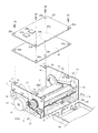
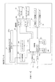
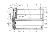
図1は、本発明の一実施形態による熱転写プリンタの筐体を取り外した状態の分解斜視図である。図2は、図1に示した一実施形態による熱転写プリンタに含まれる回路部の回路構成を示したブロック図である。図3〜図9は、図1に示した本発明の一実施形態による熱転写プリンタの詳細構造を示した図である。まず、図1〜図9を参照して、本発明の一実施形態による熱転写プリンタの構造について説明する。なお、本実施形態では、プリンタ装置の一例である熱転写プリンタに本発明を適用した場合について説明する。 FIG. 1 is an exploded perspective view of a thermal transfer printer according to an embodiment of the present invention with a housing removed. 2 is a block diagram showing a circuit configuration of a circuit unit included in the thermal transfer printer according to the embodiment shown in FIG. 3 to 9 are views showing the detailed structure of the thermal transfer printer according to the embodiment of the present invention shown in FIG. First, the structure of a thermal transfer printer according to an embodiment of the present invention will be described with reference to FIGS. In the present embodiment, a case where the present invention is applied to a thermal transfer printer which is an example of a printer apparatus will be described.
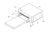
本発明の一実施形態による熱転写プリンタは、図1に示すように、金属製のシャーシ1と、印字を行うための印字ヘッド2と、印字ヘッド2に対向するように配置されたプラテンローラ3(図8参照)と、金属製の送りローラ4(図8参照)と、送りローラギア5と、所定の押圧力で送りローラ4を押圧する金属製の押さえローラ6(図8参照)と、樹脂製の下部用紙ガイド7aと、樹脂製の上部用紙ガイド7bと、ゴム製の給紙ローラ8と、給紙ローラギア9と、ゴム製の排紙ローラ10と、排紙ローラギア11と、インクシート巻取リール12と、モータブラケット13と、用紙14を搬送するためのステッピングモータ15と、印字ヘッド2を回動させるためのステッピングモータ16と、揺動可能な揺動ギア17と、複数の中間ギア18〜21(図4参照)と、インクシートカートリッジ22(図3参照)を支持するインクシートカートリッジ支持部23と、熱転写プリンタの動作を制御する回路部24(図2参照)を構成する配線基板25と、天板26と、シャーシ1を内部に収納する筐体27(図3参照)とを備えている。また、本実施形態による熱転写プリンタには、図3に示すように、20枚の用紙14を印刷することが可能なインクシート32が収納されたインクシートカートリッジ22と、熱転写プリンタに供給する用紙14を収納するための用紙トレイ28とが着脱可能に装着されている。
As shown in FIG. 1, a thermal transfer printer according to an embodiment of the present invention includes a
また、図1に示すように、シャーシ1は、一方側面1aと、他方側面1bと、底面1cとを有している。また、シャーシ1の一方側面1aには、上記したモータブラケット13が取り付けられている。また、シャーシ1の他方側面1bには、インクシートカートリッジ22を挿入するための挿入孔1dが設けられている。また、一方側面1aの上端部および他方側面1bの上端部には、それぞれ、配線基板25を取り付けるための取付部1eが2つずつ形成されている。また、取付部1eには、配線基板25を固定するためのネジ29が螺合されるネジ孔1fが形成されている。また、図8に示すように、シャーシ1の底面1cには、用紙14の前端部および後端部を検出するための用紙センサ30aおよび30bが設けられている。
Moreover, as shown in FIG. 1, the
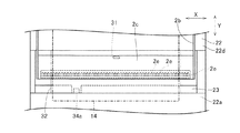
また、印字ヘッド2は、図8に示すように、支持軸2aと、アーム部2bと、ヘッド部2cと、ヘッド部2cに取り付けられる樹脂製のヘッドカバー2dとを含んでいる。また、印字ヘッド2は、図1に示すように、シャーシ1の両側面の内側に、支持軸2aを中心として回動可能に取り付けられている。また、印字ヘッド2のヘッド部2cには、図6に示すように、電圧パルスが印加されて発熱する複数の発熱体2eが、ヘッド部2cの用紙14の幅方向(X方向)に沿って所定の間隔を隔てて一列に設けられている。また、発熱体2eは、印刷時に、1つの発熱体2eが1つのドットを形成するように構成されている。また、印字ヘッド2の底面部の発熱体2eの近傍には、印字ヘッド2の発熱体2e近傍の温度を検出するための温度検出素子チップ31が設けられている。
As shown in FIG. 8, the
また、プラテンローラ3(図5参照)は、シャーシ1の両側面の内側に回転可能に配置されている。また、送りローラ4は、図4に示すように、送りローラギア5に挿入される送りローラギア挿入部4aを有する。また、送りローラ4は、シャーシ1に取り付けられた図示しない送りローラ軸受に回転可能に支持されている。また、押さえローラ6(図8参照)は、図示しない押さえローラ軸受に回転可能に支持されている。
Further, the platen roller 3 (see FIG. 5) is rotatably disposed inside both side surfaces of the
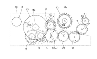
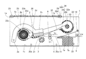
また、本実施形態では、図4に示すように、モータブラケット13に取り付けられたステッピングモータ15の軸部には、モータギア15aが取り付けられている。また、ステッピングモータ15は、インクシート巻取リール12のギア部12aと、給紙ローラギア9と、排紙ローラギア11と、送りローラギア5とを駆動させるための駆動源としての機能を有する。また、ステッピングモータ16は、印字ヘッド2(図8参照)をプラテンローラ3(図8参照)に対して押圧するように、印字ヘッド2の上面を押圧する図示しない押圧部材などの駆動源としての機能を有する。
In the present embodiment, as shown in FIG. 4, a
また、本実施形態では、インクシート巻取リール12(図4参照)は、図8に示すように、インクシートカートリッジ22の巻取部22aの内部に回転可能に配置された巻取ボビン22bに係合することによって、供給ボビン22cから供給されるインクシート32を巻取ボビン22bに巻き取るように構成されている。これにより、印刷回数の増加に伴って巻取ボビン22bに巻き取られた印刷済みのインクシート32の外径が大きくなる(図9参照)ので、同じ長さ(単位送出量)のインクシート32を搬送する場合であっても、印刷を行うほどインクシート巻取リール12の回転量が少なくなるように構成されている。すなわち、印刷回数の増加に伴って単位送出量のインクシート32を搬送するのに必要なステッピングモータ15のステップ数が少なくなるように構成されている。具体的には、本実施形態では、後述するインクシート32のインクシート頭出し識別部32f(単位送出量)を搬送するのに必要なステッピングモータ15のステップ数は、1枚目の印刷を行うときが137、17枚目の印刷を行うときが87、18枚目の印刷を行うときが84、19枚目の印刷を行うときが81、20枚目の印刷を行うときが78であった。また、インクシート巻取リール12のギア部12aは、図4に示すように、揺動ギア17が揺動することによって係合するように配置されている。
In this embodiment, the ink sheet take-up reel 12 (see FIG. 4) is disposed on a take-up
また、図8に示すように、下部用紙ガイド7aは、送りローラ4および押さえローラ6の近傍に設置されている。また、下部用紙ガイド7aには、用紙トレイ28に収納された用紙14のサイズを認識するための2つのスイッチ部33a(図1参照)を有する用紙サイズ認識スイッチ33が設けられている。また、上部用紙ガイド7bは、図8に示すように、下部用紙ガイド7aの上部に取り付けられている。この上部用紙ガイド7bは、給紙時には、用紙14が下面側を通過するようにして印刷部への給紙経路に案内するとともに、排紙時には、用紙14が上面側を通過するようにして排紙経路に案内する機能を有する。
Further, as shown in FIG. 8, the
また、インクシートカートリッジ支持部23は、図1および図8に示すように、シャーシ1の両側面の内側に配置されている。また、インクシートカートリッジ支持部23には、透過型のシート頭出しセンサ34の受光部34aが取り付けられている。なお、シート頭出しセンサ34の発光部34bは、シート頭出しセンサ34の受光部34aとインクシート32を挟んで対向するように、配線基板25に取り付けられている。このシート頭出しセンサ34は、本発明の「検出手段」および「透過型センサ」の一例である。
Further, the ink sheet
また、配線基板25は、図1に示すように、天板26を介してシャーシ1の取付部1eに取り付けられている。具体的には、配線基板25は、配線基板25の4つの孔25aおよび天板26の4つの孔26aに通された4個のネジ29をシャーシ1の取付部1eのネジ孔1fに締め付けることによって固定されている。また、配線基板25には、回路部24を構成する電子部品25bと、上記したシート頭出しセンサ34の発光部34bとが取り付けられている。また、天板26には、配線基板25に取り付けられたシート頭出しセンサ34を構成する発光部34bがシャーシ1側に露出されるための切欠部26bが形成されている。
Moreover, the
また、本実施形態では、シート頭出しセンサ34は、図8に示すように、受光部34aと発光部34bとの間に配置された後述するインクシート32の各色頭出し識別部32e(図7参照)およびインクシート頭出し識別部32f(図7参照)を検出することにより、インクシート32の頭出しを行うために設けられている。
In the present embodiment, as shown in FIG. 8, the
また、本実施形態では、筐体27は、図3に示すように、蓋部材27aおよび27bと、LED(発光ダイオード)27cとを含んでいる。また、筐体27の蓋部材27aは、用紙トレイ28を熱転写プリンタに装着するために設けられている。また、筐体27の蓋部材27bは、インクシートカートリッジ22を熱転写プリンタに装着するために設けられている。また、筐体27のLED27cは、インクシートカートリッジ22のインクシート32の残量が少ない場合に点滅することによって、ユーザに警告するために設けられている。なお、LED27cは、本発明の「警告手段」の一例である。
In the present embodiment, the
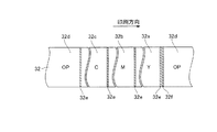
また、インクシートカートリッジ22には、インクシート32が巻き付けられた供給ボビン22cが回転可能に内部に配置された供給部22dが設けられている。このインクシート32は、図7に示すように、Y色(イエロー)印字シート32a、M色(マゼンダ)印字シート32b、C色(シアン)印字シート32cの3色のシートと、印刷された用紙14の印刷面を保護するための透明のOP(オーバーコート)シート32dとを、それぞれ、20組有している。すなわち、このインクシートカートリッジ22では、20枚の用紙14に印刷することが可能である。
Further, the
また、Y色(イエロー)印字シート32a、M色(マゼンダ)印字シート32b、C色(シアン)印字シート32cおよびOP(オーバーコート)シート32dの境界部には、それぞれ、各色頭出し識別部32eが設けられている。また、各色頭出し識別部32eは、遮光部からなるとともに、約5mmの印刷方向に沿った長さを有している。また、各色頭出し識別部32eは、シート頭出しセンサ34に検出されることにより、Y色(イエロー)印字シート32a、M色(マゼンダ)印字シート32b、C色(シアン)印字シート32cおよびOP(オーバーコート)シート32dを、それぞれ、各シートの印刷開始位置まで搬送させるために設けられている。なお、各色頭出し識別部32eは、本発明の「識別部」の一例である。
Also, each color
また、本実施形態では、OP(オーバーコート)シート32dとY色(イエロー)印字シート32aとの境界部には、OP(オーバーコート)シート32d側にインクシート頭出し識別部32fが設けられている。また、インクシート頭出し識別部32fは、遮光部からなるとともに、約5mmの印刷方向に沿った長さを有している。また、インクシート頭出し識別部32fは、インクシート頭出し識別部32fおよびY色(イエロー)印字シート32aの先頭部分にある各色頭出し識別部32eがシート頭出しセンサ34に検出されることにより、インクシート32を印刷開始位置まで搬送させるために設けられている。なお、インクシート頭出し識別部32fは、本発明の「識別部」の一例である。
In the present embodiment, an ink sheet
また、図5に示すように、インクシートカートリッジ22の供給部22dの端部には、1つまたは2つの凹部が設けられた当接部22eが設けられている。この当接部22eの凹部は、インクシート認識スイッチ35の1つまたは2つのスイッチ部35aに対応するように設けられている。これにより、インクシートカートリッジ22を熱転写プリンタに装着すると、凹部に対応するインクシート認識スイッチ35のスイッチ部35aが入力状態とならないので、入力されるスイッチ部35aと入力されないスイッチ部35aとの組合せにより、インクシートカートリッジ22の種類およびインクシート32の種類が認識されるように構成されている。
Further, as shown in FIG. 5, an abutting
また、図1に示すように、用紙トレイ28の端面部には、1つまたは2つの凹部を有する当接部28aが設けられている。この当接部28aの凹部は、用紙サイズ認識スイッチ33の1つまたは2つのスイッチ部33aに対応するように設けられている。これにより、用紙トレイ28を熱転写プリンタに装着すると、凹部に対応する用紙サイズ認識スイッチ33のスイッチ部33aが入力状態とならないので、入力されるスイッチ部33aと入力されないスイッチ部33aとの組合せにより、用紙トレイ28の種類および用紙14のサイズが認識されるように構成されている。
As shown in FIG. 1, the end surface portion of the
また、図2に示すように、回路部24は、カウンタ24gを有する制御部24aと、印字ヘッド2の発熱体2eの温度を制御するヘッドコントローラ24bと、2つのモータドライバ24cと、A/D変換部24dと、ROM24eと、RAM24fとを含んでいる。制御部24aは、印刷動作全体を制御する機能を有する。また、ヘッドコントローラ24bは、印字ヘッド2の発熱体2eに電圧パルスを印加することによって、発熱体2eの温度を制御する機能を有する。また、モータドライバ24cは、電圧パルスを印加することによって、ステッピングモータ15および16の回転を制御する機能を有する。また、A/D変換部24dは、印字ヘッド2の発熱体2eの近傍に設けられた温度検出素子チップ31からのアナログ電圧値を、デジタル電圧値に変換する機能を有する。また、カウンタ24gは、制御部24aにより、モータドライバ24cがステッピングモータ15に印加する電圧パルス数に基づいて、ステッピングモータ15のステップ数をカウントする機能を有する。
As shown in FIG. 2, the
ここで、本実施形態では、制御部24aは、インクシート残量判定処理を行うことにより、インクシート32の残量が少ない場合に筐体27のLED27cを点滅させてユーザに警告する機能を有している。具体的には、制御部24aは、インクシート32のインクシート頭出し識別部32f(図7参照)がシート頭出しセンサ34に検出されている間に制御部24aのカウンタ24gによりステッピングモータ15のステップ数をカウントするとともに、そのカウントされたステップ数がROM24eに記憶された所定の値(本実施形態では85)よりも小さい場合に、インクシート32の残量が少ないことをRAM24fに記憶させる機能を有する。また、制御部24aは、RAM24fにインクシート32の残量が少ないことが記憶されている場合に、LED27cを点滅させる機能も有する。すなわち、制御部24aは、インクシート頭出し識別部32fを搬送するのに必要なステッピングモータ15のステップ数が所定の値(本実施形態では85)よりも小さい場合に、LED27cを点滅させてユーザにインクシート32の残量が少ないことを警告するように構成されている。また、インクシート頭出し識別部32fを搬送するのに必要なステッピングモータ15のステップ数は、上記のように、1枚目の印刷を行うときが137、17枚目の印刷を行うときが87、18枚目の印刷を行うときが84であるので、制御部24aは、ステップ数が87以上の17枚目までの印刷が行われている間はユーザにインクシート32の残量が少ないことを警告することはなく、ステップ数が85未満(84)の18枚目の印刷が行われるときに初めてユーザにインクシート32の残量が少ないことを警告するように構成されている。
Here, in the present embodiment, the
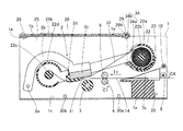
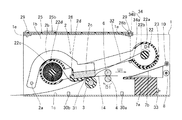
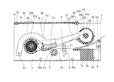
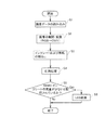
図10および図11は、図1に示した本実施形態による熱転写プリンタの印刷動作を説明するための断面図である。図12は、図1に示した本実施形態による熱転写プリンタの印刷動作を説明するためのフローチャートである。図1〜図4、図6〜図8および図10〜図12を参照して、本実施形態による熱転写プリンタの印刷動作について説明する。 10 and 11 are cross-sectional views for explaining the printing operation of the thermal transfer printer according to the present embodiment shown in FIG. FIG. 12 is a flowchart for explaining the printing operation of the thermal transfer printer according to the present embodiment shown in FIG. The printing operation of the thermal transfer printer according to the present embodiment will be described with reference to FIGS. 1 to 4, 6 to 8, and FIGS. 10 to 12.
まず、図12のステップS1において、制御部24aにより、画像データの読み込みが行われる。この後、ステップS2において、制御部24aにより、読み込まれた画像データがRAM24f(図2参照)に展開された後、制御部24aにより、画像データがRGBデータからCMYデータに変換される。なお、RGBデータは、光の三原色(R:レッド、G:グリーン、B:ブルー)から構成されており、CMYデータは、色の三原色(C:シアン、M:マゼンダ、Y:イエロー)から構成されている。
First, in step S1 in FIG. 12, the
次に、ステップS3において、インクシートカートリッジ22のインクシート32および用紙トレイ28(図1参照)内の用紙14が印刷開始位置に搬送される。ステップS3における用紙14の給紙動作は、図8に示すように、まず、シート頭出しセンサ34によってインクシート頭出し識別部32f(図7参照)およびY色(イエロー)印字シート32aの先頭部分にある各色頭出し識別部32e(図7参照)が認識されるまでインクシート32が巻き取られる。これにより、Y色(イエロー)印字シート32aの頭出しがされるとともに、インクシート残量判定処理が行われる。なお、このインクシート残量判定処理については、後に詳細に説明する。
Next, in step S3, the
そして、給紙時には、図4に示すように、ステッピングモータ15が駆動するのに伴って、ステッピングモータ15に取り付けられたモータギア15aが図4の矢印C3方向に回転し、中間ギア18および19を介して、送りローラギア5が図4の矢印C1方向に回転する。そして、送りローラギア5が図4の矢印C1方向に回転するのに伴って、中間ギア20および21を介して、給紙ローラギア9が図4の矢印C4方向に回転する。これにより、図8に示すように、給紙ローラ8が図8の矢印C4方向に回転するので、給紙ローラ8の下面側に接触する用紙14が給紙方向(図8の矢印T1方向)に搬送される。その結果、図10に示すように、用紙14は、下部用紙ガイド7aに案内されて、送りローラ4および押さえローラ6により印刷開始位置まで搬送される。
At the time of paper feeding, as shown in FIG. 4, as the stepping
この際、図4に示すように、揺動ギア17は、巻取リール12のギア部12aから離間される方向(図4の矢印C2方向)に揺動されて、巻取リール12のギア部12aとは係合しない。これにより、給紙時には、巻取リール12のギア部12aが回転しないので、巻取ボビン22bおよび供給ボビン22c(図8参照)に巻き付けられたインクシート32は巻き取られない。
At this time, as shown in FIG. 4, the
次に、ステップS4において、印刷動作が行われる。このステップS4における印刷動作は、制御部24aにより、モータドライバ22c(図2参照)を介して、ステッピングモータ16(図1参照)が駆動される。そして、ステッピングモータ16により図示しない押圧部材が回動されることによって、図10に示すように、印字ヘッド2のヘッド部2cがプラテンローラ3の方向に回動される。これにより、印字ヘッド2の発熱体2e(図6参照)が、インクシート32および用紙14を介して、プラテンローラ3を押圧する。
Next, in step S4, a printing operation is performed. In the printing operation in step S4, the stepping motor 16 (see FIG. 1) is driven by the
そして、図4に示すように、ステッピングモータ15が駆動するのに伴って、ステッピングモータ15に取り付けられたモータギア15aが矢印D3方向に回転し、中間ギア18および19を介して、送りローラギア5が矢印D1方向に回転する。これにより、送りローラ4は、矢印D1方向に回転する送りローラギア5の回転に伴って、図10の矢印D1方向に回転するので、用紙14は排紙方向(図10の矢印U1方向)に搬送される。また、揺動可能な揺動ギア17は、インクシート巻取リール12のギア部12aに係合する方向(矢印D2方向)に揺動されて、インクシート巻取リール12のギア部12aと係合する。これにより、インクシート巻取リール12(図4参照)のギア部12aが矢印D4方向に回転するので、図10に示すように、供給ボビン22cに巻き付けられたインクシート32が巻取ボビン22bに巻き取られる。
Then, as shown in FIG. 4, as the stepping
この際、用紙14を排紙方向(矢印U1方向)に搬送するとともにインクシート32を巻き取りながら、印字ヘッド2の発熱体2e(図6参照)により用紙14にY色(イエロー)印字シート32a(図7参照)のインクが印刷される。そして、Y色(イエロー)印字シート32aの印刷が終了すると、図11に示すように、用紙14は、上部用紙ガイド7bに案内されながら、排紙ローラ10により搬送可能な位置まで搬送された状態となっている。
At this time, the
次に、ステッピングモータ16(図1参照)により図示しない押圧部材が上方向に回動されると、印字ヘッド2のヘッド部2cがプラテンローラ3から離間する方向に回動される。そして、シート頭出しセンサ34によってM色(マゼンダ)印字シート32bの先頭部分にある各色頭出し識別部32e(図7参照)が認識されるまでインクシート32が巻き取られる。これにより、M色(マゼンダ)印字シート32bの頭出しがされる。そして、上記と同様に用紙14が印刷開始位置まで搬送され、印刷動作が行われる。その後、C色(シアン)印字シート32cおよびOP(オーバーコート)シート32dにおいても、上記と同様の給紙動作および印刷動作が用紙14に行われる。
Next, when a pressing member (not shown) is rotated upward by the stepping motor 16 (see FIG. 1), the
そして、印刷が終了した用紙14は、図11に示すように、上部用紙ガイド7bに案内されながら、排紙ローラ10により排紙される。この際、ステッピングモータ15(図4参照)および各種ギアは、印刷時に用紙14を排紙方向(図10の矢印U1方向)に搬送する場合と同様の動作が行われる。これにより、排紙ローラギア11(図4参照)が矢印D5方向に回転する。
Then, as shown in FIG. 11, the printed
そして、ステップS5において、制御部24aにより、RAM24fにインク残量が少ないと記憶されているかどうか判断される。そして、制御部24aにより、RAM24fにインク残量が少ないと記憶されていないと判断された場合には、熱転写プリンタの印刷動作が終了される。その一方、制御部24aにより、RAM24fにインク残量が少ないと記憶されていると判断された場合には、ステップS6に移り、制御部24aにより、筐体27に設けられたLED27c(図3参照)が点滅されて熱転写プリンタの印刷動作が終了される。
In step S5, the
図13は、図1に示した本実施形態による熱転写プリンタのインクシート残量判定処理を説明するためのフローチャートである。図1、図2、図7および図13を参照して、本実施形態による熱転写プリンタのインクシート残量判定処理について説明する。 FIG. 13 is a flowchart for explaining the ink sheet remaining amount determination process of the thermal transfer printer according to the present embodiment shown in FIG. With reference to FIG. 1, FIG. 2, FIG. 7, and FIG. 13, the remaining ink sheet determination process of the thermal transfer printer according to the present embodiment will be described.
まず、図13のステップS7において、制御部24aにより、インクシート頭出し識別部32f(図7参照)がシート頭出しセンサ34に検出されたときの、カウンタ24g(図2参照)にカウントされているステッピングモータ15(図1参照)のステップ数(X1)が検出される。次に、ステップS8において、制御部24aにより、インクシート頭出し識別部32fがシート頭出しセンサ34に検出されなくなったときの、カウンタ24gにカウントされているステッピングモータ15のステップ数(X2)が検出される。
First, in step S7 of FIG. 13, the
そして、ステップS9において、制御部24aにより、インクシート頭出し識別部32fがシート頭出しセンサ34に検出されなくなったときのステッピングモータ15のステップ数(X2)と、インクシート頭出し識別部32fがシート頭出しセンサ34に検出されたときのステッピングモータ15のステップ数(X1)との差が所定の値(本実施形態では85)よりも小さいかどうか判断される。すなわち、インクシート頭出し識別部32f(単位送出量)を搬送するのに必要なステッピングモータ15のステップ数(=X2−X1)が、上記のように、1枚目の印刷を行うときが137、17枚目の印刷を行うときが87、18枚目の印刷を行うときが84であることにより、18枚目以降の印刷であるかどうかが判断される。そして、制御部24aにより、X2とX1との差が所定の値(本実施形態では85)よりも大きい(17枚目以前の印刷を行う)と判断された場合には、インクシート残量判定処理が終了される。その一方、制御部24aにより、X2とX1との差が所定の値(本実施形態では85)よりも小さい(18枚目以降の印刷を行う)と判断された場合には、ステップS10に移り、制御部24aにより、RAM24fにインクシートの残量が少ないと記憶され、インクシート残量判定処理が終了される。
In step S9, the
本実施形態では、上記のように、インクシート32を巻取ボビン22bに巻き取るためのステッピングモータ15と、インクシート頭出し識別部32fおよび各色頭出し識別部32eを検出するシート頭出しセンサ34とを設けるとともに、シート頭出しセンサ34によりインクシート頭出し識別部32fが検出されている間のステッピングモータ15のステップ数が所定の値(本実施形態では85)よりも小さい場合に、インクシート32の残量が少ないことをユーザに警告するように構成することによって、印刷の進行に伴って巻取ボビン22bに巻き付けられた印刷済みのインクシート32の外径が徐々に大きくなることにより、インクシート32の単位送出量当たりのステッピングモータ15のステップ数が徐々に小さくなることに起因して、シート頭出しセンサ34によりインクシート32のインクシート頭出し識別部32fが検出されている間のステッピングモータ15のステップ数も徐々に小さくなるので、そのステップ数が所定の値(本実施形態では85)よりも小さくなったことにより、容易に、インクシート32の残量が少なくなったと判断することができ、その結果、インクシート32の残量が少ないことをユーザに警告することができる。また、インクシート32の頭出しを行うためのシート頭出しセンサ34でインクシート頭出し識別部32fを検出する間のステッピングモータ15のステップ数を制御部24aにより測定すればよいので、インクシート32の残量を測定するための部材を別途設ける必要がない。このため、部品点数の増加を抑制しながら、インクシート32の単位送出量当たりのステッピングモータ15のステップ数が所定の値(本実施形態では85)よりも小さい場合に、インクシート32の残量が少ないことをユーザに警告することができる。
In the present embodiment, as described above, the stepping
また、本実施形態では、インクシート32の残量が少ないことをユーザに警告するLED27cと、印刷動作の制御を行うとともに、シート頭出しセンサ34によりインクシート頭出し識別部32fが検出されている間のステッピングモータ15のステップ数が所定の値(本実施形態では85)よりも小さい場合に、LED27cにインクシート32の残量が少ないことをユーザに警告させる制御部24aとを設けることによって、LED27cおよび制御部24aにより、容易に、インクシート32の残量が少ないことをユーザに警告することができる。
Further, in the present embodiment, the
また、本実施形態では、インクシートを挟むように配置された受光部34aおよび発光部34bからなるシート頭出しセンサ34を熱転写プリンタに設けるとともに、遮光部からなるインクシート頭出し識別部32fをインクシートカートリッジ22のインクシート32に設けることによって、受光部34aおよび発光部34bからなるシート頭出しセンサ34で遮光部を検出することにより、容易に、インクシート32のインクシート頭出し識別部32fを検出することができる。
In the present embodiment, the
なお、今回開示された実施形態は、すべての点で例示であって制限的なものではないと考えられるべきである。本発明の範囲は、上記した実施形態の説明ではなく特許請求の範囲によって示され、さらに特許請求の範囲と均等の意味および範囲内でのすべての変更が含まれる。 The embodiment disclosed this time should be considered as illustrative in all points and not restrictive. The scope of the present invention is shown not by the above description of the embodiment but by the scope of claims for patent, and all modifications within the meaning and scope equivalent to the scope of claims for patent are included.
たとえば、上記実施形態では、熱転写プリンタに本発明を適用する例を示したが、本発明はこれに限らず、熱転写方式ファクシミリなどの熱転写プリンタ以外のプリンタ装置にも適用可能である。 For example, in the above-described embodiment, an example in which the present invention is applied to a thermal transfer printer has been described.
また、上記実施形態では、20枚の印刷が可能なインクシートカートリッジにおいて、18枚目の印刷を行うときにユーザにインクシートの残量が少ないことを警告するように構成したが、本発明はこれに限らず、17枚目の印刷を行うときにユーザにインクシートの残量が少ないことを警告するようにしてもよい。具体的には、インクシート頭出し識別部がシート頭出しセンサに検出されている間のステッピングモータのステップ数が85よりも小さい場合に(18枚目の印刷時はステップ数84)インクシートの残量が少ないことを警告するように構成していたが、インクシート頭出し識別部がシート頭出しセンサに検出されている間のステッピングモータのステップ数が88よりも小さい場合に(17枚目の印刷時はステップ数87)インクシートの残量が少ないことを警告するように構成してもよい。 In the above embodiment, the ink sheet cartridge capable of printing 20 sheets is configured to warn the user that the remaining amount of ink sheet is low when performing printing on the 18th sheet. Not limited to this, the user may be warned that the remaining amount of ink sheet is low when the 17th sheet is printed. Specifically, when the number of steps of the stepping motor is smaller than 85 while the ink sheet cueing identification unit is detected by the sheet cueing sensor (step number 84 when printing the 18th sheet), Although it is configured to warn that the remaining amount is low, when the number of steps of the stepping motor is smaller than 88 while the ink sheet cueing identification unit is detected by the sheet cueing sensor (17th sheet) When printing is performed, the number of steps 87) may be configured to warn that the ink sheet is low.
また、上記実施形態では、筐体に設けられたLEDを点滅させることによりインクシートの残量が少ないことをユーザに警告するように構成したが、本発明はこれに限らず、筐体にLEDを設ける代わりに、筐体に表示部を設け、表示部にインクシートの残量が少ないことを表示させるようにしてもよい。 Moreover, in the said embodiment, although it comprised so that a user might be warned that the residual amount of an ink sheet is low by blinking LED provided in the housing | casing, this invention is not limited to this, LED in a housing | casing is comprised. Alternatively, a display unit may be provided in the housing, and the display unit may display that the remaining amount of the ink sheet is low.
また、上記実施形態では、20枚の印刷が可能なインクシートカートリッジにおいて、18枚目の印刷を行うときにユーザにインクシートの残量が少ないことを警告するように構成していたが、本発明はこれに限らず、制御部により、インクシートカートリッジおよびインクシートの種類に基づいて、ユーザにインクシートの残量が少ないことを警告する印刷枚数を変更するように構成してもよい。たとえば、20枚の印刷が可能なインクシートカートリッジと、40枚の印刷が可能なインクシートカートリッジとを装着することが可能な熱転写プリンタにおいて、インクシート認識スイッチにより20枚の印刷が可能なインクシートカートリッジが装着されたと検出されたときには、制御部により、18枚目の印刷を行うときにユーザにインクシートの残量が少ないことを警告するとともに、インクシート認識スイッチにより40枚の印刷が可能なインクシートカートリッジが装着されたと検出されたときには、制御部により、38枚目の印刷を行うときにユーザにインクシートの残量が少ないことを警告するようにしてもよい。 In the above embodiment, the ink sheet cartridge capable of printing 20 sheets is configured to warn the user that the remaining amount of ink sheet is low when printing the 18th sheet. The invention is not limited to this, and the control unit may change the number of printed sheets that warns the user that the remaining amount of the ink sheet is low based on the types of the ink sheet cartridge and the ink sheet. For example, in a thermal transfer printer capable of mounting an ink sheet cartridge capable of printing 20 sheets and an ink sheet cartridge capable of printing 40 sheets, an ink sheet capable of printing 20 sheets by an ink sheet recognition switch When it is detected that the cartridge is mounted, the control unit warns the user that the remaining amount of ink sheet is low when printing the 18th sheet, and 40 sheets can be printed by the ink sheet recognition switch. When it is detected that the ink sheet cartridge is mounted, the control unit may warn the user that the remaining amount of the ink sheet is low when the 38th sheet is printed.
15 ステッピングモータ
22 インクシートカートリッジ
22b 巻取りボビン
24a 制御部
27c LED(警告手段)
32 インクシート
32e 各色頭出し識別部(識別部)
32f インクシート頭出し識別部(識別部)
34 シート頭出しセンサ(検出手段、透過型センサ)
15
32
32f Ink sheet cue identification part (identification part)
34 Sheet cueing sensor (detection means, transmission type sensor)
Claims (5)
前記インクシートの識別部は、遮光部からなるとともに、最初に印刷される色のシートと最後に印刷される色のシートとの境界部に設けられたインクシート頭出し識別部と、複数の各色の境界部に設けられた各色頭出し識別部とを含み、
前記検出手段は、前記インクシートを挟むように配置された一対の透過型センサを含み、
前記プリンタ本体に設けられ、前記インクシートの残量が少ないことをユーザに警告する警告手段と、前記プリンタ本体に設けられ、印刷動作の制御を行うとともに、一対の前記透過型センサにより前記インクシートのインクシート頭出し識別部が検出されている間の前記ステッピングモータのステップ数が所定の値よりも小さい場合に、前記警告手段に前記インクシートの残量が少ないことをユーザに警告させる制御部とをさらに備えた、プリンタ装置。 A printer main body in which an ink sheet having an identification section and a plurality of color sheets is stored, and an ink sheet cartridge having a winding bobbin for winding the used ink sheet is detachably mounted; In a printer apparatus comprising a stepping motor provided in a printer main body for winding the ink sheet on the take-up bobbin, and a detection means provided in the printer main body for detecting an identification portion of the ink sheet,
The ink sheet identification unit includes a light shielding unit, an ink sheet cue identification unit provided at a boundary between a first printed color sheet and a last printed color sheet, and a plurality of each color Each color cue identification part provided in the boundary part,
The detection means includes a pair of transmissive sensors arranged to sandwich the ink sheet,
Warning means provided in the printer main body for warning the user that the remaining amount of the ink sheet is low, and provided in the printer main body for controlling the printing operation, and the ink sheet by the pair of transmissive sensors A control unit for causing the warning means to warn the user that the remaining amount of the ink sheet is low when the number of steps of the stepping motor is smaller than a predetermined value while the ink sheet cueing identification unit is detected And a printer device.
前記プリンタ本体に設けられ、前記インクシートを前記巻取ボビンに巻き取るためのステッピングモータと、
前記プリンタ本体に設けられ、前記インクシートの識別部を検出する検出手段とを備え、
前記検出手段により前記インクシートの識別部が検出されている間の前記ステッピングモータのステップ数が所定の値よりも小さい場合に、前記インクシートの残量が少ないことをユーザに警告する、プリンタ装置。 A printer main body in which an ink sheet having an identification unit is stored and an ink sheet cartridge having a winding bobbin for winding the used ink sheet is detachably mounted;
A stepping motor provided in the printer body for winding the ink sheet onto the winding bobbin;
A detection unit provided in the printer body for detecting an identification part of the ink sheet;
A printer device that warns the user that the remaining amount of the ink sheet is low when the number of steps of the stepping motor is smaller than a predetermined value while the identification unit of the ink sheet is being detected by the detection unit .
前記プリンタ本体に設けられ、印刷動作の制御を行うとともに、前記検出手段により前記インクシートの識別部が検出されている間の前記ステッピングモータのステップ数が所定の値よりも小さい場合に、前記警告手段に前記インクシートの残量が少ないことをユーザに警告させる制御部とをさらに備えた、請求項2に記載のプリンタ装置。 Warning means provided in the printer body for warning the user that the remaining amount of the ink sheet is low;
The warning is provided when the number of steps of the stepping motor is smaller than a predetermined value provided in the printer main body to control a printing operation and while the identification unit of the ink sheet is detected by the detection unit. The printer apparatus according to claim 2, further comprising: a control unit that causes the user to warn that the remaining amount of the ink sheet is low.
前記インクシートの識別部は、遮光部からなる、請求項2または3に記載のプリンタ装置。 The detection means includes a pair of transmissive sensors arranged to sandwich the ink sheet,
The printer apparatus according to claim 2, wherein the ink sheet identification unit includes a light shielding unit.
前記インクシートの識別部は、最初に印刷される色のシートと最後に印刷される色のシートとの境界部に設けられたインクシート頭出し識別部と、複数の各色の境界部に設けられた各色頭出し識別部とを含み、
前記検出手段により前記インクシートのインクシート頭出し識別部が検出されている間の前記ステッピングモータのステップ数が所定の値よりも小さい場合に、前記インクシートの残量が少ないことをユーザに警告する、請求項2〜4のいずれか1項に記載のプリンタ装置。 The ink sheet has a plurality of color sheets;
The ink sheet identification unit is provided at an ink sheet cue identification unit provided at a boundary between a first printed color sheet and a last printed color sheet, and at a plurality of color boundary units. Each color cue identification part,
When the number of steps of the stepping motor is smaller than a predetermined value while the ink sheet cueing identifying part of the ink sheet is detected by the detection means, a warning is given to the user that the remaining amount of the ink sheet is low The printer device according to any one of claims 2 to 4.
Priority Applications (1)
| Application Number | Priority Date | Filing Date | Title |
|---|---|---|---|
| JP2006013267A JP2007190873A (en) | 2006-01-23 | 2006-01-23 | Printer apparatus |
Applications Claiming Priority (1)
| Application Number | Priority Date | Filing Date | Title |
|---|---|---|---|
| JP2006013267A JP2007190873A (en) | 2006-01-23 | 2006-01-23 | Printer apparatus |
Publications (1)
| Publication Number | Publication Date |
|---|---|
| JP2007190873A true JP2007190873A (en) | 2007-08-02 |
Family
ID=38446921
Family Applications (1)
| Application Number | Title | Priority Date | Filing Date |
|---|---|---|---|
| JP2006013267A Pending JP2007190873A (en) | 2006-01-23 | 2006-01-23 | Printer apparatus |
Country Status (1)
| Country | Link |
|---|---|
| JP (1) | JP2007190873A (en) |
Cited By (1)
| Publication number | Priority date | Publication date | Assignee | Title |
|---|---|---|---|---|
| JP2010228207A (en) * | 2009-03-26 | 2010-10-14 | Sato Knowledge & Intellectual Property Institute | Printer apparatus, ink ribbon cartridge, ink ribbon state recognition method, ink ribbon state recognition program. |
Citations (10)
| Publication number | Priority date | Publication date | Assignee | Title |
|---|---|---|---|---|
| JPH0768875A (en) * | 1993-09-03 | 1995-03-14 | Hitachi Ltd | Thermal transfer recorder |
| JPH10250169A (en) * | 1997-03-11 | 1998-09-22 | Brother Ind Ltd | Transfer type image recording device |
| JPH11105315A (en) * | 1997-09-30 | 1999-04-20 | Casio Comput Co Ltd | Printing equipment |
| JPH11240219A (en) * | 1998-02-25 | 1999-09-07 | Canon Inc | Ink sheet cassette and thermal transfer printer |
| JP2000190604A (en) * | 1998-12-28 | 2000-07-11 | Sony Corp | Ink ribbon for image printer and image printer using the same |
| JP2000211221A (en) * | 1999-01-27 | 2000-08-02 | Sony Corp | Ink ribbon for image printer and image printer using the same |
| JP2000318281A (en) * | 1999-05-10 | 2000-11-21 | Hitachi Ltd | Form processing equipment |
| JP2004130568A (en) * | 2002-10-09 | 2004-04-30 | Hitachi Ltd | Printing device |
| JP2004284206A (en) * | 2003-03-24 | 2004-10-14 | Mitsubishi Electric Corp | Ink ribbon take-up device |
| JP2005041163A (en) * | 2003-07-24 | 2005-02-17 | Sharp Corp | Ribbon support structure, ink ribbon structure, and image printing apparatus |
-
2006
- 2006-01-23 JP JP2006013267A patent/JP2007190873A/en active Pending
Patent Citations (10)
| Publication number | Priority date | Publication date | Assignee | Title |
|---|---|---|---|---|
| JPH0768875A (en) * | 1993-09-03 | 1995-03-14 | Hitachi Ltd | Thermal transfer recorder |
| JPH10250169A (en) * | 1997-03-11 | 1998-09-22 | Brother Ind Ltd | Transfer type image recording device |
| JPH11105315A (en) * | 1997-09-30 | 1999-04-20 | Casio Comput Co Ltd | Printing equipment |
| JPH11240219A (en) * | 1998-02-25 | 1999-09-07 | Canon Inc | Ink sheet cassette and thermal transfer printer |
| JP2000190604A (en) * | 1998-12-28 | 2000-07-11 | Sony Corp | Ink ribbon for image printer and image printer using the same |
| JP2000211221A (en) * | 1999-01-27 | 2000-08-02 | Sony Corp | Ink ribbon for image printer and image printer using the same |
| JP2000318281A (en) * | 1999-05-10 | 2000-11-21 | Hitachi Ltd | Form processing equipment |
| JP2004130568A (en) * | 2002-10-09 | 2004-04-30 | Hitachi Ltd | Printing device |
| JP2004284206A (en) * | 2003-03-24 | 2004-10-14 | Mitsubishi Electric Corp | Ink ribbon take-up device |
| JP2005041163A (en) * | 2003-07-24 | 2005-02-17 | Sharp Corp | Ribbon support structure, ink ribbon structure, and image printing apparatus |
Cited By (1)
| Publication number | Priority date | Publication date | Assignee | Title |
|---|---|---|---|---|
| JP2010228207A (en) * | 2009-03-26 | 2010-10-14 | Sato Knowledge & Intellectual Property Institute | Printer apparatus, ink ribbon cartridge, ink ribbon state recognition method, ink ribbon state recognition program. |
Similar Documents
| Publication | Publication Date | Title |
|---|---|---|
| KR100636135B1 (en) | Image Alignment Printing Method of Duplexer | |
| JP2007510557A (en) | Reverse image ID card printer | |
| JP2004059192A (en) | Printer | |
| KR20060043828A (en) | Printer and how to print | |
| WO2013137216A1 (en) | Sensor level adjustment device for printer, and sensor level adjustment method | |
| JPH1059599A (en) | Device for performing work by using consumption web and method therefor | |
| US7614810B2 (en) | Printer | |
| US20090003908A1 (en) | Image recording device and determination method | |
| JP3674863B2 (en) | Image forming apparatus and image forming apparatus control method | |
| JP4687312B2 (en) | Printer device | |
| JP6546514B2 (en) | Printer | |
| US7961207B2 (en) | Image generating apparatus | |
| JP2008213287A (en) | Image forming apparatus | |
| JP2007001264A (en) | Printing apparatus and ribbon cassette | |
| JP4736610B2 (en) | Printer device | |
| JP6031799B2 (en) | Printing device | |
| JP2008179044A (en) | Image forming apparatus | |
| JPH0577538A (en) | Printer | |
| JP2008265005A (en) | Image forming apparatus | |
| JP2018158558A (en) | Printing device | |
| JPH0193384A (en) | Thermal transfer type color recorder | |
| JP2007223200A (en) | Printer and method for detecting residual amount of ink ribbon | |
| JPH01210366A (en) | Thermal transfer recording device | |
| JP2008265225A (en) | Image forming device | |
| JPH0732692A (en) | Ink sheet transport device |
Legal Events
| Date | Code | Title | Description |
|---|---|---|---|
| A621 | Written request for application examination |
Free format text: JAPANESE INTERMEDIATE CODE: A621 Effective date: 20081126 |
|
| A977 | Report on retrieval |
Effective date: 20110124 Free format text: JAPANESE INTERMEDIATE CODE: A971007 |
|
| A131 | Notification of reasons for refusal |
Free format text: JAPANESE INTERMEDIATE CODE: A131 Effective date: 20110208 |
|
| A521 | Written amendment |
Effective date: 20110408 Free format text: JAPANESE INTERMEDIATE CODE: A523 |
|
| A131 | Notification of reasons for refusal |
Free format text: JAPANESE INTERMEDIATE CODE: A131 Effective date: 20120228 |
|
| A521 | Written amendment |
Free format text: JAPANESE INTERMEDIATE CODE: A523 Effective date: 20120427 |
|
| A02 | Decision of refusal |
Effective date: 20130416 Free format text: JAPANESE INTERMEDIATE CODE: A02 |