JP2007191925A - Lattice panel and lattice panel mounting structure - Google Patents
Lattice panel and lattice panel mounting structure Download PDFInfo
- Publication number
- JP2007191925A JP2007191925A JP2006011213A JP2006011213A JP2007191925A JP 2007191925 A JP2007191925 A JP 2007191925A JP 2006011213 A JP2006011213 A JP 2006011213A JP 2006011213 A JP2006011213 A JP 2006011213A JP 2007191925 A JP2007191925 A JP 2007191925A
- Authority
- JP
- Japan
- Prior art keywords
- lattice
- panel
- lattice panel
- tool
- flat plate
- Prior art date
- Legal status (The legal status is an assumption and is not a legal conclusion. Google has not performed a legal analysis and makes no representation as to the accuracy of the status listed.)
- Pending
Links
Images
Landscapes
- Panels For Use In Building Construction (AREA)
- Floor Finish (AREA)
- Steps, Ramps, And Handrails (AREA)
Abstract
【課題】格子形状に形成するリブからなる格子状部材と前記格子状部材の上に載置される平板で構成される格子パネルであって、従前のとおり建物構造体等の躯体に対して格子パネルが外れることがない十分な強度で固定でき、取付金具がパネル上に露出して外観を損なうことがなく、また現場における作業工程が削減できる格子パネルおよび前記格子パネルの取付構造を提供する。
【解決手段】格子パネルの建物等に取り付けるための係合具を、あらかじめ前記格子パネルの枠内に嵌入する。
【選択図】図1
The present invention relates to a lattice panel comprising a lattice-shaped member made of ribs formed in a lattice shape and a flat plate placed on the lattice-shaped member. Provided are a lattice panel and a structure for attaching the lattice panel, which can be fixed with sufficient strength so that the panel does not come off, the mounting bracket is not exposed on the panel and the appearance is not impaired, and the work process in the field can be reduced.
An engaging tool for attaching a lattice panel to a building or the like is inserted into a frame of the lattice panel in advance.
[Selection] Figure 1
Description
本発明は、建物の床材や階段の踏板材等に用いられる格子パネルを建物構造体等の躯体に取り付ける格子パネルの取付構造および格子パネル材に関する。 The present invention relates to a lattice panel mounting structure and a lattice panel material for attaching a lattice panel used for a flooring material of a building, a tread material of a staircase, or the like to a housing such as a building structure.
建物の床材や階段の踏板材等に用いられる格子パネルとしては、平板と格子状部材との組み合わせで構成されたものが提案されている。この格子パネル(特に透光性を有する材料の平板と格子状部材の組み合わせである格子パネル)の従前の取付方法について具体的に説明する。 As a lattice panel used for a flooring material of a building, a tread material of a staircase, or the like, a structure composed of a combination of a flat plate and a lattice-like member has been proposed. A conventional method for attaching the lattice panel (particularly, a lattice panel that is a combination of a flat plate of a light-transmitting material and a lattice-like member) will be specifically described.
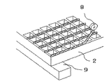
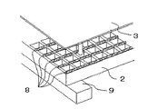
図4〜6は、格子パネルの取付方法の説明図である。まず、図4に示すように格子状部材2の格子内に凹型断面の取付金具やブロック状の留め具等の係合具4(以下、係合具という)を嵌挿し、この係合具4をパネル取付部9とボルト5等の止着手段によって連結して格子状部材2を固定する(例えば、特許文献1または特許文献2参照)。次に、図5に示すように格子状部材2の取付部9と反対側の面に接着テープ8を貼り付ける。最後に、図6に示すように平板3を接着テープ8を介在して格子状部材2に止着する。
4-6 is explanatory drawing of the attachment method of a lattice panel. First, as shown in FIG. 4, an engagement tool 4 (hereinafter referred to as an engagement tool) such as a mounting bracket or a block-shaped fastener is inserted into the lattice of the lattice-
この取付方法によれば、十分な取付強度が得られ、また取付金具がパネル上に露出して外観を損なうことなく格子パネルを固定できる。しかし、上記取付方法によれば、格子内を利用して格子状部材2を固定させるため、取付現場において格子状部材2固定した後でしか平板3と格子状部材2を組立られないので、現場における作業が多く、また平板3と格子状部材2との組立の際の位置合せが現場作業では困難であるので、接着テープロスや仕損が多くなる上、組立て時間が掛かるという欠点があった。
According to this mounting method, sufficient mounting strength can be obtained, and the grid panel can be fixed without the mounting bracket being exposed on the panel and deteriorating the appearance. However, according to the above mounting method, since the
本発明は、上記の事情に鑑みてなされたものであって、従前のとおり建物構造体等の取付部に対し、格子パネルが外れることがない十分な強度で固定でき、また取付金具がパネル上に露出して外観を損なわれないという条件を満たし、更に現場における作業工程が削減できる格子パネルと格子パネルを躯体に取り付ける格子パネルの取付構造の提供を目的とする。 The present invention has been made in view of the above circumstances, and as before, can be fixed to a mounting portion of a building structure or the like with sufficient strength that the lattice panel does not come off, and the mounting bracket is mounted on the panel. An object of the present invention is to provide a grid panel and a grid panel mounting structure for mounting the grid panel to the housing, which can satisfy the condition that the appearance is not impaired by being exposed to light and can further reduce the work process in the field.
前記目的を達成するため、請求項1の発明では、平板と、前記平板を支持する格子状部材と、が取り付けられた格子パネルにおいて、前記格子パネルを躯体に取り付けるための係合具を有し、前記係合具があらかじめ前記格子状部材の格子の孔部に嵌入されていることを特徴とする格子パネルを提供する。
In order to achieve the above object, in the invention of
請求項2の発明では、請求項1における前記係合具が雌ねじを有することを特徴としている。
The invention according to
請求項3の発明では、請求項1における前記係合具が雄ねじを有することを特徴としている。
The invention of
請求項4の発明では、請求項1における前記平板が、前記係合具の嵌入部に相当する位置に孔を有することを特徴としている。
The invention according to
請求項5の発明では、平板と、前記平板を支持する格子状部材と、が取り付けられた格子パネルを躯体に取り付ける取付構造において、前記格子状部材の格子の孔部にあらかじめ嵌入された係合具を介して格子パネルを躯体に固定することを特徴とする請求項1に記載の格子パネルの取付構造を提供する。
According to a fifth aspect of the present invention, in a mounting structure for mounting a grid panel to which a flat plate and a grid-like member that supports the flat plate are attached to a housing, the engagement is pre-inserted in a hole of the grid of the grid-like member. The grid panel mounting structure according to
請求項6の発明では、前記係合具に設けられた雌ねじに躯体の取付部側から雄ねじを螺合させ、格子パネルを躯体に固定することを特徴とする請求項2に記載の格子パネルの取付構造を提供する。 According to a sixth aspect of the invention, in the lattice panel according to the second aspect, the male screw is screwed into the female screw provided in the engaging tool from the attachment portion side of the housing, and the lattice panel is fixed to the housing. Provide mounting structure.
請求項7の発明では、前記係合具に設けられた雄ねじを躯体の取付部側から雌ねじを螺合させ、格子パネルを躯体に固定することを特徴とする請求項3に記載の格子パネルの取付構造を提供する。 According to a seventh aspect of the invention, in the lattice panel according to the third aspect, the male screw provided on the engagement tool is screwed into the female screw from the attachment portion side of the housing, and the lattice panel is fixed to the housing. Provide mounting structure.
請求項8の発明では、前記平板の前記係合具の嵌入部に相当する位置に設けられた孔から雄ねじを螺入し、前記格子状部材の格子の孔部にあらかじめ嵌入された係合具を介して格子パネルを躯体に固定することを特徴とする請求項4に記載の格子パネルを提供する。
According to an eighth aspect of the present invention, there is provided an engagement tool that is inserted into a hole of a lattice of the lattice-like member in advance by inserting a male screw from a hole provided at a position corresponding to the engagement portion of the engagement tool of the flat plate. The lattice panel according to
請求項1の発明によれば、係合具があらかじめ嵌入されているので、従前の係合具の取付部への取付の際、取付現場で施工していた接着テープ貼り付けと平板貼り付け工程が出荷前、例えば格子パネルの製造工程にて行える。これにより、現場の作業は格子パネル材の取付のみにすることができ、現場作業の効率化が図れる。また、接着テープの貼り付けおよび平板貼り付けが出荷前に行えるので、組立の際の位置合せが容易になり作業効率が良くなり、接着テープロスや仕損が減少するとともに、仕上がり状態の優れた格子パネルが製作できる。更には、組立の自動化も可能となる。
According to the invention of
請求項2または3の発明によれば、係合具が雌ねじ、または雄ねじを有しているので、格子パネル取付部側からボルトまたはナットを使用して、格子パネルの取付・固定が容易になる。
According to the invention of
請求項4の発明によれば、格子パネルの係合具嵌入部に孔を有するので、取付部の反対側の格子パネル側よりボルト等を使用して、格子パネルの取付・固定が容易になる。 According to the fourth aspect of the present invention, since the engagement member fitting portion of the lattice panel has a hole, it is easy to attach and fix the lattice panel using bolts or the like from the lattice panel side opposite to the attachment portion. .
請求項5から8のいずれか1項の発明によれば、従前のとおり建物構造体等の躯体の取付部に対し格子パネルが外れることがない十分な強度で固定でき、また取付金具がパネル上に露出して外観を損なわれることなく、生産効率および現場作業効率に優れた格子パネルの取付構造を提供することができる。
According to the invention of any one of
次に、本発明の格子パネルと格子パネルを躯体に取り付ける格子パネルの取付構造を実施例に基づいて詳細に説明する。
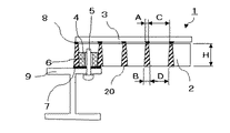
図1は本発明に係る格子パネルおよび格子パネルの取付構造(実施例1)の概略断面図である。図1に示すように、格子パネル1は格子形状に形成するリブ20からなる格子状部材2と格子状部材2の上に載置される平板3で構成され、平板3は接着テープ8を介在して格子状部材2の表側全面に止着される。
Next, the lattice panel according to the present invention and a lattice panel mounting structure for mounting the lattice panel to the housing will be described in detail based on examples.
FIG. 1 is a schematic cross-sectional view of a grid panel and a grid panel mounting structure (Example 1) according to the present invention. As shown in FIG. 1, the
格子パネル1の材料は金属材料でも樹脂材料でもよいが、格子状部材2をFRP(ガラス繊維強化プラスチック)、平板3をポリカーボネートで構成して採光性や目隠し性を考慮した床材や踏板材を形成する場合に、本発明は特に好適である。
The material of the
この格子パネル1は、建物の床材や階段の踏板材として使用されるが、他に壁材、間仕切り、天井材、あるいはテーブル等の板材として用いることができる。さらに、格子パネル1を金属で形成し、排水溝等の蓋材として用いることもできる。本発明に係る格子パネル1の取付構造は、このような用途のすべての格子パネル1に対して適用可能である。なお、格子パネル1の代表的な寸法は、例えば高さHが40mmであり、リブ20の上面幅Aが5mm、下面幅Bが7mm、格子の上面幅Cが35mm、下面幅Dが33mmである。なお、本実施例は格子の孔部の形状が矩形であるが、孔部の形状は多角形でも円形でもよい。
The
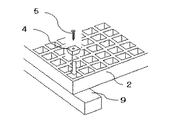
例えば建物に取り付ける際には、建物の壁面に備わる梁等の躯体の取付部9上に格子パネル1は載置され、格子状部材の格子の孔部に嵌入された係合具4、例えばブロック形状の係合具4を、ボルト5等の結合手段を介して取付部9と係合具4を固定する。
For example, when attaching to a building, the
格子パネル1における係合具4の配置は、躯体の取付部9にあわせて任意に決めることができるが、格子パネル1の4隅に配置することが、取付強度の面および外観の面からも好ましい。
The arrangement of the
格子パネル1の格子の孔部の各側面は下側が徐々に狭まるテーパ状に形成されている。具体的には、格子の孔部を構成するリブ20の厚みを下側が徐々に広がる形状としている。一方係合具4は所定厚みを有し、係合具4の各側面は格子パネル1の孔部と同様のテーパ状に形成され、このテーパ状係合具4と格子パネル1の孔部のテーパ状各側面により、互いの接触面積が増加して係合具4の格子内に対する摩擦保持力が向上し、格子パネル1は躯体9に固定されるとともに、係合具4が格子パネル1から下側に抜けることを防止できる。なお、係合具4の各側面をテーパ状としなかった場合であっても係合具4下辺の角部が格子パネル孔部のテーパ面に引っかかるので、係合具4が格子パネル1から下側に抜けることを防止できる。また、係合具4は所定厚みを有するブロック形状であるため、係合具製作の際、金型による成形後の表面が部分的に凹んだりする「ひけ」が発生しやすい。係合具4にはこのひけ防止のための切欠き(図示せず)が設けられる。
Each side surface of the hole portion of the lattice of the
係合具4にはボルト5を締結するための雌ねじ6が、係合具4のテーパー形状を成す方向と垂直方向の略中央に、係合具4のテーパー形状を成す方向に螺刻される。格子パネル1は、この雌ねじ6に格子パネルを取り付ける躯体の取付部9側からボルト5を螺合させ、取付部9に対して固定される。
A female screw 6 for fastening the
係合具4は軽量化の促進やさび等の腐食防止を考慮して樹脂材料で形成される。この樹脂材料としては適度に強度のあるものが好ましく、例えばPA(ポリアミド)、BMC(FRPの一種であり、不飽和ポリエステルが主成分の黒色樹脂)、ABS(アクリロニトリル・ブタジエン・スチレン)、PC(ポリカーボネート)、PP(ポリプロピレン)、PS(ポリスチレン)、PEEK(ポリエステルエーテルケトン)等を使用できる。なお、係合具4を透明性の樹脂材料で形成すれば、透明材料からなる格子パネル1を取り付ける際に取付具4も透明となるため、より見栄えよく格子パネル1を建物等の取付部に取り付けることができる。この透明性樹脂材料としては、アクリル、透明塩化ビニル、透明PC、透明PP、PEEK等を使用できる。取付具4を透明性樹脂材料で形成した場合、ボルト7もPCやPPの透明性樹脂で形成すれば、さらに見栄えのよい格子パネル1の取付構造を実現できる。なお、取付強度を要する場合、係合具4を金属にしてもよく、また係合具の金属部材に雌ねじを羅刻したものを係合具4に取り付けてもよい。
The
係合具4の格子内での摩擦保持力を向上させるため、係合具4の周囲にゴム等を貼り付けてもよい。また、係合具4自体を硬質の天然ゴムや合成ゴム等で形成すれば、格子内のテーパー形状に合わせて係合具4の形状が変化するので、ブロックの大きさの精度が緩くて済むために、加工性のよい係合具4を得ることができる。また、格子パネル1と躯体9の間には必要に応じゴム等のシート7が介装される。図1では係合具4とシート7は接しているが、係合具4を格子内に挿入した場合に格子内壁(枠体2の内側およびリブ3)に係合していれば、係合具4とシート7の間に空間があってもよい。これらのゴムとしては、CR(クロロプレンゴム)、EPDM(エチレン・プロピレン・ジエン三元共重合体)、NBR(ニトリル・ブタジエンゴム)、IIR(ブチルゴム)、NR(天然ゴム)、SBR(スチレン・ブタジエンゴム)、シリコン樹脂、ウレタンゴム等を使用できる。
In order to improve the friction holding force in the lattice of the
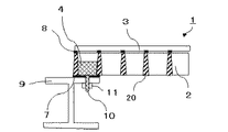
図2は本発明に係る別の格子パネルの取付構造(実施例2)を示す概略図である。
図2に示す格子パネル1の取付構造は、取付部9に対し格子パネルを固定するため、係合具4には、雄ねじ10が螺刻された部品を係合具4のテーパー形状を成す方向と垂直方向の略中央部に係合具4のテーパー形状を成す方向に取り付ける。格子パネル1は、この雄ねじ10にナット11を螺合し、取付部9に対して固定される。なお、係合具4および雄ねじ10に使用する材料は実施例1と同様である。なお、雄ねじ10は、係合具4と別の部材で製作した後取り付けてもよいし、一体形成してもよい。
FIG. 2 is a schematic view showing another lattice panel mounting structure (Example 2) according to the present invention.
In the mounting structure of the
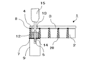
図3は本発明に係る別の格子パネルの取付構造(実施例3)を示す概略図である。
図3に示す格子パネル1の取付構造は、取付部3に対し格子パネル1を固定するため、係合具4には、係合具4のテーパー形状を成す方向と垂直方向の略中央部に係合具4のテーパー形状を成す方向に取り付け用の貫通孔12を有し、係合具4のテーパー形状を成す方向と垂直方向の係合具4の貫通孔12に相当する位置に平板は孔13を有する。格子パネル1は、この平板の孔13を利用して、係合具4の貫通孔12にボルト5を挿入し、工具15で取付部9に螺刻された雌ねじ13にボルト5を螺合させて、取付部9に固定される。なお、係合具4およびボルト5に使用する材料は実施例1と同様である。
FIG. 3 is a schematic view showing another lattice panel mounting structure (Example 3) according to the present invention.
In the mounting structure of the
以上のように、実施例1および実施例2は、取付部9側から固定が可能な場所に限られるが、図3に示す格子パネル1の取り付け構造は、取付部9と反対側の格子パネル1側からの取り付けの場合に、好適である。
As described above, Example 1 and Example 2 are limited to places where fixing can be performed from the
係合具6を本実施例ではテーパー形状を有するブロック状のものとしたが、テーパー形状でなくてもよく、また凹型断面の取付金具等でもよい。 In the present embodiment, the engaging tool 6 is a block having a tapered shape, but the engaging tool 6 may not be a tapered shape, and may be a fitting having a concave cross section.
本発明の格子パネルは、建物の床材や階段の踏板材、天井材、壁材、テーブルの板材や排水溝の蓋材等の建築用部材として適用可能であり、また本発明の格子パネルの取付構造は、格子状の貫通孔を有する板材の取付構造として、板材の材質を問わずに適用可能である。この場合、躯体としては梁や梁に固定したブラケットあるいは鉄筋コンクリートや方立て、H鋼等の建築構造体を使用できる。 The lattice panel of the present invention can be applied as a building member such as a flooring material for a building, a tread material for a staircase, a ceiling material, a wall material, a plate material for a table, or a lid material for a drainage groove. The mounting structure can be applied as a mounting structure for a plate material having a lattice-like through hole regardless of the material of the plate material. In this case, a building structure such as a beam, a bracket fixed to the beam, a reinforced concrete, a vertical frame, or H steel can be used as the frame.
1:格子パネル、2:格子状部材、3:平板、4:係合具、5:ボルト、6:雌ねじ、
7:シート、8:接着テープ、9:取付部、10:雄ねじ、11:ナット、
12:貫通孔、13:平板の孔、14:躯体の雌ねじ、15:工具、
20:リブ。
1: lattice panel, 2: lattice member, 3: flat plate, 4: engagement tool, 5: bolt, 6: female screw,
7: sheet, 8: adhesive tape, 9: mounting portion, 10: male screw, 11: nut,
12: Through-hole, 13: Hole in flat plate, 14: Female screw of housing, 15: Tool,
20: Rib.
Claims (8)
前記格子パネルを躯体に取り付けるための係合具を有し、前記係合具があらかじめ前記格子状部材の格子の孔部に嵌入されていることを特徴とする格子パネル。 In a lattice panel to which a flat plate and a lattice-like member that supports the flat plate are attached,
A lattice panel comprising: an engagement tool for attaching the lattice panel to a housing, wherein the engagement tool is inserted in advance into a hole of a lattice of the lattice member.
前記格子状部材の格子の孔部にあらかじめ嵌入された係合具を介して格子パネルを躯体に固定することを特徴とする請求項1に記載の格子パネルの取付構造。 In the mounting structure for mounting the grid panel to which the flat plate and the grid-like member supporting the flat plate are mounted to the housing,
The lattice panel mounting structure according to claim 1, wherein the lattice panel is fixed to the housing through an engagement tool that is pre-inserted in a lattice hole of the lattice member.
A male panel is screwed through a hole provided at a position corresponding to the fitting portion of the engaging tool on the flat plate, and the lattice panel is framed through the engaging tool pre-inserted in the hole portion of the lattice of the lattice-like member. The lattice panel according to claim 4, wherein the lattice panel is fixed to the grid.
Priority Applications (1)
| Application Number | Priority Date | Filing Date | Title |
|---|---|---|---|
| JP2006011213A JP2007191925A (en) | 2006-01-19 | 2006-01-19 | Lattice panel and lattice panel mounting structure |
Applications Claiming Priority (1)
| Application Number | Priority Date | Filing Date | Title |
|---|---|---|---|
| JP2006011213A JP2007191925A (en) | 2006-01-19 | 2006-01-19 | Lattice panel and lattice panel mounting structure |
Publications (1)
| Publication Number | Publication Date |
|---|---|
| JP2007191925A true JP2007191925A (en) | 2007-08-02 |
Family
ID=38447841
Family Applications (1)
| Application Number | Title | Priority Date | Filing Date |
|---|---|---|---|
| JP2006011213A Pending JP2007191925A (en) | 2006-01-19 | 2006-01-19 | Lattice panel and lattice panel mounting structure |
Country Status (1)
| Country | Link |
|---|---|
| JP (1) | JP2007191925A (en) |
Cited By (4)
| Publication number | Priority date | Publication date | Assignee | Title |
|---|---|---|---|---|
| JP2011220023A (en) * | 2010-04-13 | 2011-11-04 | Daikure Co Ltd | Attachment jig for lattice-shaped structure |
| CN104164952A (en) * | 2014-07-23 | 2014-11-26 | 南京长江都市建筑设计股份有限公司 | Hinge joint connecting structure of novel prefabricated shear stairway |
| CN111927531A (en) * | 2020-06-24 | 2020-11-13 | 中铁第四勘察设计院集团有限公司 | Prefabricated assembly type evacuation platform |
| CN116791841A (en) * | 2023-07-19 | 2023-09-22 | 浙江亚厦装饰股份有限公司 | A hollow grid wall system and its installation method |
-
2006
- 2006-01-19 JP JP2006011213A patent/JP2007191925A/en active Pending
Cited By (4)
| Publication number | Priority date | Publication date | Assignee | Title |
|---|---|---|---|---|
| JP2011220023A (en) * | 2010-04-13 | 2011-11-04 | Daikure Co Ltd | Attachment jig for lattice-shaped structure |
| CN104164952A (en) * | 2014-07-23 | 2014-11-26 | 南京长江都市建筑设计股份有限公司 | Hinge joint connecting structure of novel prefabricated shear stairway |
| CN111927531A (en) * | 2020-06-24 | 2020-11-13 | 中铁第四勘察设计院集团有限公司 | Prefabricated assembly type evacuation platform |
| CN116791841A (en) * | 2023-07-19 | 2023-09-22 | 浙江亚厦装饰股份有限公司 | A hollow grid wall system and its installation method |
Similar Documents
| Publication | Publication Date | Title |
|---|---|---|
| US11021868B2 (en) | Finishing panel fixing device | |
| US20250034883A1 (en) | Snap-in member, assembled decking combination and method of assembling decking | |
| KR200303366Y1 (en) | Connecting structure for cable tray | |
| JP2014118680A (en) | Fitting device for exterior material of curtain wall | |
| JP2004525316A (en) | Blind rivet nut with improved seal retention | |
| JP2009046830A (en) | Load-bearing floor | |
| JP6270095B2 (en) | Unit room | |
| JP5103271B2 (en) | Mounting bracket for mounting the object to be mounted on the mounting rail | |
| JP2005232833A (en) | Lattice panel mounting structure | |
| KR20110126982A (en) | Fixture for installation of building exterior materials | |
| CN112103113B (en) | Waterproof structure of soft rubber key and installation method | |
| CN201045527Y (en) | Air conditioner outdoor unit ceiling structure | |
| JP2024142730A (en) | Louver materials and system ceilings | |
| JP5004129B2 (en) | Frame material for sign display | |
| JP5316494B2 (en) | Sash structure | |
| JP2005090137A (en) | Panel mounting structure | |
| JP2007205031A (en) | Lattice panel assembling jig and assembling method | |
| CN222040374U (en) | Bracket structure, vehicle door and vehicle | |
| KR200268847Y1 (en) | Connecting means for ceiling panels | |
| KR101324727B1 (en) | Device for fixing internal and external construction materials | |
| CN212897084U (en) | An installation structure for the top surface of a prefabricated toilet | |
| JP2006037444A (en) | Ceiling installing structure of unit room | |
| CN221989781U (en) | A wall veneer panel installation structure that is easy to disassemble and assemble | |
| KR102126267B1 (en) | Wall assembly structure of elevator car more smoothly | |
| KR200290834Y1 (en) | Signboard mounting bracket |