JP2007192577A - Vehicle collision object discrimination device - Google Patents
Vehicle collision object discrimination device Download PDFInfo
- Publication number
- JP2007192577A JP2007192577A JP2006008858A JP2006008858A JP2007192577A JP 2007192577 A JP2007192577 A JP 2007192577A JP 2006008858 A JP2006008858 A JP 2006008858A JP 2006008858 A JP2006008858 A JP 2006008858A JP 2007192577 A JP2007192577 A JP 2007192577A
- Authority
- JP
- Japan
- Prior art keywords
- load
- vehicle
- sensor
- bumper
- width direction
- Prior art date
- Legal status (The legal status is an assumption and is not a legal conclusion. Google has not performed a legal analysis and makes no representation as to the accuracy of the status listed.)
- Pending
Links
Images




Classifications
-
- B—PERFORMING OPERATIONS; TRANSPORTING
- B60—VEHICLES IN GENERAL
- B60R—VEHICLES, VEHICLE FITTINGS, OR VEHICLE PARTS, NOT OTHERWISE PROVIDED FOR
- B60R19/00—Wheel guards; Radiator guards, e.g. grilles; Obstruction removers; Fittings damping bouncing force in collisions
- B60R19/02—Bumpers, i.e. impact receiving or absorbing members for protecting vehicles or fending off blows from other vehicles or objects
- B60R19/48—Bumpers, i.e. impact receiving or absorbing members for protecting vehicles or fending off blows from other vehicles or objects combined with, or convertible into, other devices or objects, e.g. bumpers combined with road brushes, bumpers convertible into beds
- B60R19/483—Bumpers, i.e. impact receiving or absorbing members for protecting vehicles or fending off blows from other vehicles or objects combined with, or convertible into, other devices or objects, e.g. bumpers combined with road brushes, bumpers convertible into beds with obstacle sensors of electric or electronic type
Landscapes
- Engineering & Computer Science (AREA)
- Mechanical Engineering (AREA)
- Force Measurement Appropriate To Specific Purposes (AREA)
Abstract
【課題】衝突物体判別が正確で、単純且つ製造も容易な車両用衝突物体判別装置の提供。
【解決手段】バンパ内で車幅方向に延在される荷重センサ1をもつ。荷重センサ1はスペーサ13とスペーサ13により規制される間隔を空けて対面し且つ外部から加えられる荷重に応じて変化する物理的性質を検出する荷重検出手段とをもつ複数のセンサ部と、複数のセンサ部がそれぞれいずれかの面上で車幅方向に並設された帯状部材11及び12と、を有し、複数のセンサ部は、車両外部からバンパを介して加わる荷重に対する応答特性が近似するように、車幅方向の固定された部位に応じて感度を変化させている。具体的には、スペーサ13によって形成される空間Sの径dを変化させることでセンサ部の感度を調節している。車幅方向に感度の異なる複数のセンサ部を帯状の部材に固定した状態で提供することで、構成及び組み立てを単純化でき、出力される信号の後処理も容易になる。
【選択図】図3
An object of the present invention is to provide a collision object discriminating apparatus for a vehicle that is accurate, simple and easy to manufacture.
A load sensor 1 extending in a vehicle width direction in a bumper is provided. The load sensor 1 has a plurality of sensor units having a load detection means for detecting a physical property that changes according to a load applied from the outside, facing the spacer 13 with an interval regulated by the spacer 13, and a plurality of sensor units. Each of the sensor parts includes belt-like members 11 and 12 arranged in parallel in the vehicle width direction on either surface, and the plurality of sensor parts approximate response characteristics to a load applied from outside the vehicle via a bumper. As described above, the sensitivity is changed according to the fixed part in the vehicle width direction. Specifically, the sensitivity of the sensor unit is adjusted by changing the diameter d of the space S formed by the spacer 13. By providing a plurality of sensor portions having different sensitivities in the vehicle width direction in a state of being fixed to the belt-like member, the configuration and assembly can be simplified, and post-processing of the output signal is facilitated.
[Selection] Figure 3
Description
本発明は、車両に衝突する物体を判別する車両用衝突物体判別装置に関する。本発明は、好適には車両への衝突物体が歩行者か否かを判別する装置に適用される。 The present invention relates to a vehicle collision object discrimination device that discriminates an object that collides with a vehicle. The present invention is preferably applied to an apparatus for determining whether or not an object colliding with a vehicle is a pedestrian.
近年、車両衝突に対する歩行者保護に関する要望が強くなっている。それに応じて種々の歩行者保護装置が提案されている。ただ、車両が衝突した物体が歩行者でない場合にこれらの歩行者保護装置を作動させることは様々な悪影響を派生させる。従って、衝突物体が歩行者か否かを判別することが要望されている。車両衝突における衝突荷重検出のために、従来より種々の技術が開示されているが、衝突物体が歩行者か否かを判別する装置として、衝突荷重が所定レベルを超えた後の衝突荷重の増加率を用いて歩行者の判別を行う装置が開示されている(特許文献1)。 In recent years, there has been an increasing demand for pedestrian protection against vehicle collisions. Accordingly, various pedestrian protection devices have been proposed. However, operating these pedestrian protection devices when the object that the vehicle collides with is not a pedestrian can cause various adverse effects. Therefore, it is desired to determine whether or not the collision object is a pedestrian. Various techniques have been disclosed for detecting a collision load in a vehicle collision, but as an apparatus for determining whether or not a collision object is a pedestrian, an increase in the collision load after the collision load exceeds a predetermined level. An apparatus for discriminating a pedestrian using a rate is disclosed (Patent Document 1).
ここで、車幅方向の部位で感度が異なると同じ物体が衝突しても同じ物体であると判別できないという不都合がある。従って、物体の衝突を荷重の変化により測定する装置においては車幅方向の部位による荷重センサの感度特性を均質化することが求められる(特許文献2)。
しかしながら、特許文献2に記載の装置では、部位毎に衝撃の伝達を局所的に変化させるために複雑な構成を採用しており、更なる簡略化が求められる。 However, the apparatus described in Patent Document 2 employs a complicated configuration in order to locally change the impact transmission for each part, and further simplification is required.
本発明は上記実情に鑑み完成されたものであり、衝突した物体の判別が部位によって影響され難い車両用衝突物体判別装置であって単純な構造で製造も容易なのものを提供することを解決すべき課題とする。 The present invention has been completed in view of the above circumstances, and solves the problem of providing a collision object discriminating apparatus for a vehicle in which discrimination of a collided object is not easily influenced by a part, which is simple in structure and easy to manufacture. It should be a challenge.
上記課題を解決する本発明の車両用衝突物体判別装置は、バンパ内で車幅方向に延在されている荷重センサを有する車両用衝突物体判別装置であって、
前記荷重センサは、
1以上のスペーサと、該スペーサにより規制される間隔を空けて対面し且つ外部から加えられる荷重に応じて変化する物理的性質を検出する荷重検出手段と、をもつ複数のセンサ部と、
前記複数のセンサ部がそれぞれいずれかの面上に前記車幅方向に並設された帯状部材と、を有し、
前記複数のセンサ部は、車両外部から前記バンパを介して加わる荷重に対する応答特性が近似するように、車幅方向の固定された部位に応じてそれぞれの感度を変化させていることを特徴とする。
A vehicle collision object discrimination device of the present invention that solves the above problems is a vehicle collision object discrimination device having a load sensor extending in a vehicle width direction in a bumper,
The load sensor is
A plurality of sensor units having one or more spacers, and load detection means for detecting a physical property that faces a space regulated by the spacers and changes according to a load applied from the outside;
A plurality of sensor parts each having a belt-like member arranged in parallel in the vehicle width direction on any surface;
The plurality of sensor units change their sensitivities in accordance with fixed portions in the vehicle width direction so that response characteristics to a load applied from the outside of the vehicle via the bumper are approximated. .
車幅方向に感度の異なる複数のセンサ部を帯状の部材に固定した状態で提供することで、構成及び組み立てを単純化することができる。また、出力される信号の後処理が容易になる。 By providing a plurality of sensor parts having different sensitivities in the vehicle width direction in a state of being fixed to the belt-like member, the configuration and assembly can be simplified. Further, post-processing of the output signal is facilitated.
そして、前記帯状部材は互いに対面して配設される第1帯状部材及び第2帯状部材からなり、前記複数のセンサ部は該第1及び第2帯状部材の間に挟設されることで製造が容易になり望ましい。 The belt-shaped member is composed of a first belt-shaped member and a second belt-shaped member arranged to face each other, and the plurality of sensor portions are manufactured by being sandwiched between the first and second belt-shaped members. Is easier and desirable.
ここで、前記荷重検出手段は、第1接点と、感圧インクを備え該第1接点に接触する圧力に応じて該第1接点との間の抵抗値が変化する第2接点とをもつことが望ましい。感圧インクは組成を変化させることで、対応できる圧力の大きさ(すなわち感度)を変更することが容易であるからである。従って、前記車幅方向の部位に応じた感度の変化は前記感圧インクの種類を変化させて行うことができる。 Here, the load detecting means has a first contact and a second contact that has pressure-sensitive ink and changes a resistance value between the first contact and the first contact. Is desirable. This is because it is easy to change the magnitude of pressure that can be handled (that is, sensitivity) by changing the composition of the pressure-sensitive ink. Therefore, the change in sensitivity according to the position in the vehicle width direction can be performed by changing the type of the pressure-sensitive ink.
そして、前記複数のセンサ部は、このスペーサの厚み及び弾性、並びに該スペーサにより形成される空間の大きさのうちの少なくとも1つを調節することで、加わる荷重に対する前記センサ部の感度を容易に調節できる。 The plurality of sensor units easily adjust the sensitivity of the sensor unit to an applied load by adjusting at least one of the thickness and elasticity of the spacer and the size of the space formed by the spacer. Can be adjusted.
更に、本発明の車両用衝突物体判別装置は、バンパ内で車幅方向に延設され衝突エネルギーを吸収するバンパアブソーバと、該バンパアブソーバの車両後方側にて前記バンパアブソーバに沿って延在されたバンパリンフォースと、そのバンパリンフォースの車両後方側の車幅方向両側にて車両前後方向に延在された支持部材と、を有し、前記バンパアブソーバ及び前記バンパリンフォースの間に前記荷重センサが挟持されている構成をもつことが望ましい。 Further, the vehicle collision object discriminating device of the present invention extends along the bumper absorber on the vehicle rear side of the bumper absorber, which is extended in the vehicle width direction in the bumper and absorbs collision energy. And a supporting member extending in the vehicle front-rear direction on both sides in the vehicle width direction on the vehicle rear side of the bumper force, and the load between the bumper absorber and the bumper force It is desirable to have a configuration in which the sensor is sandwiched.
(実施例)
本発明の車両用衝突物体判別装置を具現化した実施例について図面を例示しながら以下詳細に説明する。本実施例の車両用衝突物体判別装置は、エンジンルームの前方など車両の前方に配設される。本車両用衝突物体判別装置は、図1及び2に示すように、荷重センサ1とバンパアブソーバ2とバンパリンフォース3と演算手段(図略)とを有する。
(Example)
DESCRIPTION OF EMBODIMENTS Embodiments of a vehicle collision object discrimination device according to the present invention will be described below in detail with reference to the drawings. The vehicle collision object discrimination device of the present embodiment is disposed in front of the vehicle such as in front of the engine room. As shown in FIGS. 1 and 2, the vehicle collision object determination device includes a
バンパアブソーバ2はバンパカバー5内にて車幅方向に延設されている部材である。そして、万が一の衝突時にその衝突エネルギーを吸収できる発泡材のような構造を有する。バンパリンフォース3はバンパアブソーバ2との間で荷重センサ1を挟持している。荷重センサ1は上下方向に2つ並設される。バンパリンフォース3はサイドメンバ4の先端部に固定され、バンパーを補強する部材である。
The bumper absorber 2 is a member extending in the vehicle width direction within the
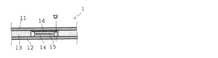
荷重センサ1は、図3に示すように、第1帯状部材11と第2帯状部材12と、センサ部としての、スペーサ13、接点14及び15とをもつ。第1及び第2帯状部材11及び12は帯状の部材であり、接点14及び15とスペーサ13とを間に挟持している。第1及び第2帯状部材11及び12の長さは荷重を測定した部位の長さに応じて決定される。例えば、バンパの幅方向についてすべて荷重を測定できるようにバンパの幅とほぼ同じ長さにすることができる。そして、第1及び第2帯状部材11及び12の幅は採用する接点14及び15、並びにスペーサ13の大きさによって決定される。
As shown in FIG. 3, the
接点14(第1接点)及び接点15(第2接点)は組み合わせられて荷重検出手段を構成する部材であり、感圧インクを少なくとも一方に備えることが望ましい。感圧インクを組み合わせることにより外部からの圧力に応じて抵抗値が変化する。感圧インクの他、銀などの金属やカーボンなどの導電材料を組み合わせたり単独で用いたりすることもできる。また、感圧インクを採用しなくても、接点14及び15の間の接触を検出するようにすれば一定以上の荷重の有無を検出することができる。また、荷重の測定に際して、抵抗値の変化を測定する他、電気容量、起電力などを測定しても良い。例えば、接点14及び15の間に誘電体を挟持するなどした上で電気容量を測定することで接点14及び15の間に加わる荷重が測定できる。また、誘電体に代えて圧電性材料を挟持することで荷重の印加を直接的に電圧変化(起電力)として測定することができる。抵抗値などの変化を測定する方法としては特に限定しないが、電圧変化を直接的に測定したり、発振回路などを形成した上でその発振周波数を測定するなどの一般的な方法が採用できる。
The contact point 14 (first contact point) and the contact point 15 (second contact point) are members that are combined to form a load detection means, and it is desirable to include pressure-sensitive ink in at least one of them. By combining the pressure sensitive ink, the resistance value changes according to the pressure from the outside. In addition to the pressure-sensitive ink, a metal such as silver or a conductive material such as carbon can be combined or used alone. Even if no pressure-sensitive ink is used, if a contact between the
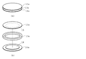
スペーサ13は荷重センサ1に加わる荷重を規制する手段である。すなわち、荷重センサ1に加わる荷重は、スペーサ13により形成される空間の大きさにより変化する。つまり、空間の大きさが大きくなると、より小さな荷重でもたわみの程度が大きくなって、荷重センサ1に加わる荷重も相対的に大きくなる。スペーサ13を構成する材料は特に限定されず、プラスチックや金属などの薄板から形成することができる。ゴムや発泡材などの弾性体を採用することもできる。スペーサ13は各センサ部毎に独立した形態とすることもできるが、本実施形態では、図4に示すように、センサ部が配設される部位に応じて径の異なる円板状の空間Sが形成された一体形状の板状部材を採用している。図3及び4にて示したように、空間Sの径dを制御することで、センサ部の感度を調節している。つまり、径dを大きくするにつれ、接点14及び15の間を近接させるために必要な応力が小さくでき、より小さな外力によっても接点14及び15の間に加わる力を大きくすることができる。従って、径dを大きくするほど、対応するセンサ部の感度を高くすることができる。
The
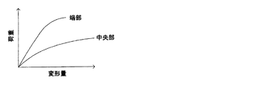
例えば、一般的なバンパの形状として、中央付近は平坦であり、端部の曲率が大きいものが挙げられる。そのような場合には端部付近の剛性が高いので、図5に示すように、同程度の加重が加わっても中央部付近よりも変形量が小さくなる。そこで、中央付近に配設したセンサ部よりも端部に配設したセンサ部におけるスペーサ13に形成された空間Sの径dを大きくすることで、端部に配設されたセンサ部の方がより小さな荷重により変形することになり、部位による変形量のばらつきを小さくすることができる。
For example, as a general bumper shape, the shape near the center is flat and the end portion has a large curvature. In such a case, the rigidity in the vicinity of the end portion is high, and as shown in FIG. 5, the deformation amount is smaller than that in the vicinity of the central portion even when a similar weight is applied. Therefore, by increasing the diameter d of the space S formed in the
また、荷重による感度を調節するために、スペーサ13に形成する空間Sの径dを調節する方法のほか、スペーサ13の厚みを調節する方法がある。スペーサ13の厚みが小さいほど、より小さな荷重により接点14及び15の間に加わる力を大きくすることができる。部位毎にてスペーサ13の厚みを調節することが困難である場合には、図6に示すように、接点14及び15のいずれか(図6では接点15)の底面に第2スペーサ16を配置して接点14及び15の間に加わる荷重を調節することができる。スペーサ13の厚みを調節する場合と同様に、第2スペーサ16の厚みを大きくすると、接点14及び15の間に加わる荷重が大きくなって感度を向上できる。
In addition to adjusting the diameter d of the space S formed in the
また、スペーサ13として、第1及び第2帯状部材11及び12と同程度の大きさで一体的な部材を採用しているが、図7に示すように、各センサ部毎に独立したスペーサ13aを採用することもできる。
Further, as the
図8に示すように、各々のセンサ部について独立に配線を行いそれぞれの接点14及び15の間の抵抗値を測定することで加わった荷重の大きさを測定している。ここで、各々のセンサ部の配線方法としては、その他に、全体又は幾つかのグループに分けて荷重を測定することもできる。その場合には、まとめて荷重を測定するグループ毎に、センサ部を並列や直列に接続する。一括して接続されている各センサ部について抵抗値を測定することで、それらのセンサ部に加わった荷重を一括して算出することができる。
As shown in FIG. 8, the magnitude | size of the applied load is measured by wiring independently about each sensor part, and measuring the resistance value between each
演算手段は各々のセンサ部における抵抗値などの物理量の変化を測定し、その物理量の変化から衝突した物体を判別する手段である。 The computing means is means for measuring a change in physical quantity such as a resistance value in each sensor unit and discriminating an object that has collided from the change in the physical quantity.
以下、本実施例の車両用衝突物体判別装置が衝突した物体の判別を行う動作を説明する。 In the following, an operation for discriminating a collided object by the vehicular collision object discriminating apparatus of this embodiment will be described.
まず、車両の前面部にもうけられた車両バンパーが歩行者又はそれ以上の質量をもつ物体(車両など)に衝突する。 First, a vehicle bumper provided on the front surface of the vehicle collides with a pedestrian or an object (such as a vehicle) having a mass greater than that.
車両バンパーが物体に衝突すると、車両バンパーには、衝突荷重が加わり、車両の進行方向において圧縮する方向に応力が働く。この応力は、車両側から見たときには、バンパーカバー5、バンパアブソーバ2、荷重センサ1、バンパリンフォース3、そしてサイドメンバ4の順で加わる。ここで、サイドメンバ4及びバンパリンフォース3は、いずれも剛性を有する部材であり、バンパリンフォース3の前面に配設された荷重センサ1には、バンパリンフォース3に加わる応力が加わっている。
When the vehicle bumper collides with an object, a collision load is applied to the vehicle bumper, and stress is applied in the direction of compression in the traveling direction of the vehicle. When viewed from the vehicle side, this stress is applied in the order of the
従って、荷重センサ1には外部から加わった荷重が圧縮される方向に加わることになる。そのために、荷重センサ1は、物体が衝突した部位近傍におけるスペーサ13及びスペーサ13で区画された空間Sが撓む。その結果、それぞれのセンサ部が備える接点14及び15の間に加わる荷重が大きくなり接点14及び15に設けた手段に応じた物理量(抵抗値)の変化が現れることになる。ここで、衝突した物体から加わる荷重が同一である場合に、各々のセンサ部で発生する物理量の変化が均質になるように、空間Sの径dや、接点14及び15の間の接触の程度がセンサ部の配置されているバンパの位置に応じて調節されている。従って、バンパに対してどの部位に物体が衝突しても、同程度の物体であれば、センサ部から出力される信号の大きさは概ね同程度になることが期待できる。従って、従来の車両用衝突物体判別装置において行っていたような、バンパの部位に応じたセンサ部からの出力の補正を演算手段にて行うことなく、そのまま判別に用いることが可能になる。
Therefore, the load applied from the outside is applied to the
このセンサ部からの出力からバンパに加えられた圧力を算出し、その圧力の値から衝突した物体の判別を行う。例えば、演算手段は、バンパに加えられた荷重(圧力)を荷重が加えられた時間で積分し、この積分値を衝突直前の車両の速度で割ることで、バンパに衝突した物体の質量を算出することができる。算出した質量が歩行者の体重の範囲(例えば、小児(6歳児)〜大人の体重)にあるときには、衝突した物体は歩行者であると判断し、歩行者保護装置(図略)にその装置を作動させる作動信号を出力することで適正な動作を行う。その結果、衝突した歩行者に加えられるダメージを低減することが可能になる。ここで、演算手段からの作動信号が入力される歩行者保護装置は、特に限定されるものではなく、一般的な歩行者保護装置が採用できる。 The pressure applied to the bumper is calculated from the output from the sensor unit, and the collision object is determined from the pressure value. For example, the computing means calculates the mass of the object that collided with the bumper by integrating the load (pressure) applied to the bumper by the time when the load was applied and dividing this integrated value by the speed of the vehicle immediately before the collision. can do. When the calculated mass is in the range of the pedestrian's weight (for example, a child (6 years old) to an adult's weight), the collision object is determined to be a pedestrian, and the pedestrian protection device (not shown) has its device Appropriate operation is performed by outputting an activation signal that activates. As a result, it is possible to reduce the damage applied to the colliding pedestrian. Here, the pedestrian protection device to which the operation signal from the calculation means is input is not particularly limited, and a general pedestrian protection device can be adopted.
本実施例の車両用衝突物体判別装置は、荷重を測定するセンサ部の感度を配置される部位に応じて調節することで、演算手段などの後処理にて補正などを行う必要が無くなり、装置の単純化が実現できる。 The vehicle collision object discriminating apparatus according to the present embodiment eliminates the need for performing correction or the like in post-processing such as calculation means by adjusting the sensitivity of the sensor unit for measuring the load according to the portion to be arranged. Can be simplified.
(変形態様1及び2)
変形態様1の車両用衝突物体判別装置は、図9に示すように、実施例の車両用衝突物体判別装置における荷重センサをチャンバ式の荷重センサ1a、1b及び1cに代えた以外、その作用効果もほぼ同等の装置である。
(
As shown in FIG. 9, the vehicle collision object discriminating apparatus according to the
荷重センサ1a、1b及び1cは、内部に空気などの気体を密閉しそれぞれ独立したチャンバとそれらチャンバ内の圧力を測定する圧力センサとから構成される。前述したように、バンパの中央部近傍の方が端部近傍よりも衝突による荷重が伝達しやすい。つまり、バンパ中央部近傍の方が端部よりも、衝突により同じ荷重が加わっても、より多くの変形が生じることになる。
Each of the
従って、端部近傍に配設する荷重センサ1b及び1cにおけるチャンバ内の圧力の方を、中央部近傍に配設する荷重センサ1aにおけるチャンバ内の圧力よりも高くすることで、端部に配置する荷重センサ1b及び1cのチャンバ内の圧力の方が、同じ変形量でもより大きな圧力を示すようにしている。ここで、内圧の比を変形量の相対比に応じて設定することで、同じ衝突荷重により異なる変形量が生じても同じ圧力値を出力することができ、バンパの部位による荷重センサの感度が均質化できる。
Therefore, the pressure in the chamber in the
変形態様2の車両用衝突物体判別装置は、図には示さないが、実施例における車両用衝突物体判別装置における荷重センサに代えて、チューブ式の荷重センサを採用した以外は、その作用効果もほぼ同等の装置である。ここで、チューブ式の荷重センサは一端部が閉塞され、他端部にて圧力を測定するものである。チューブ式の荷重センサはバンパの幅方向いっぱいに配設されている。前述したように、衝突荷重によるバンパの変形量はバンパの部位によって異なるので、チューブの剛性を部位によって変化させている。具体的には、同一の荷重が加えられた場合に、変形量が小さい部位の剛性を低くし、変形量が大きい部位の剛性を高くしている。剛性の調節は、チューブの厚み(厚い方が剛性が高くなる)、チューブの材質、チューブの径などにより制御できる。また、同一の変形量でも大きな圧力変化が生じるように、衝突荷重により圧縮される方向におけるチューブの長さを大きくすることもできる。 Although the vehicle collision object discriminating apparatus according to modification 2 is not shown in the drawing, its effect is also obtained except that a tube-type load sensor is used instead of the load sensor in the vehicle collision object discrimination apparatus in the embodiment. It is an almost equivalent device. Here, one end of the tube type load sensor is closed, and the pressure is measured at the other end. The tube type load sensor is arranged in the entire width direction of the bumper. As described above, the amount of deformation of the bumper due to the collision load differs depending on the part of the bumper, so that the rigidity of the tube is changed depending on the part. Specifically, when the same load is applied, the rigidity of a portion with a small deformation amount is reduced and the rigidity of a portion with a large deformation amount is increased. The adjustment of the rigidity can be controlled by the tube thickness (thicker is higher in rigidity), the tube material, the tube diameter, and the like. In addition, the length of the tube in the direction compressed by the collision load can be increased so that a large pressure change occurs even with the same deformation amount.
1…荷重センサ
11…第1帯状部材 12…第2帯状部材 13…スペーサ 14、15…接点
2…バンパアブソーバ
3…バンパリンフォース
4…サイドメンバ
5…バンパカバー
DESCRIPTION OF
Claims (6)
前記荷重センサは、
1以上のスペーサと、該スペーサにより規制される間隔を空けて対面し且つ外部から加えられる荷重に応じて変化する物理的性質を検出する荷重検出手段と、をもつ複数のセンサ部と、
前記複数のセンサ部がそれぞれいずれかの面上に前記車幅方向に並設された帯状部材と、を有し、
前記複数のセンサ部は、車両外部から前記バンパを介して加わる荷重に対する応答特性が近似するように、車幅方向の固定された部位に応じてそれぞれの感度を変化させていることを特徴とする車両用衝突物体判別装置。 A vehicle collision object discrimination device having a load sensor extending in a vehicle width direction in a bumper,
The load sensor is
A plurality of sensor units having one or more spacers, and load detection means for detecting a physical property that faces a space regulated by the spacers and changes according to a load applied from the outside;
A plurality of sensor parts each having a belt-like member arranged in parallel in the vehicle width direction on any surface;
The plurality of sensor units change their sensitivities in accordance with fixed portions in the vehicle width direction so that response characteristics to a load applied from the outside of the vehicle via the bumper are approximated. Vehicle collision object discrimination device.
前記複数のセンサ部は該第1及び第2帯状部材の間に挟設される請求項1に記載の車両用衝突物体判別装置。 The belt-shaped member is composed of a first belt-shaped member and a second belt-shaped member that are arranged to face each other,
The vehicle collision object determination device according to claim 1, wherein the plurality of sensor units are sandwiched between the first and second belt-like members.
該バンパアブソーバの車両後方側にて前記バンパアブソーバに沿って延在されたバンパリンフォースと、
そのバンパリンフォースの車両後方側の車幅方向両側にて車両前後方向に延在された支持部材と、を有し、
前記バンパアブソーバ及び前記バンパリンフォースの間に前記荷重センサが挟持されている請求項1〜5のいずれかに記載の車両用衝突物体判別装置。 A bumper absorber that extends in the vehicle width direction within the bumper and absorbs collision energy;
A bumper reinforcement extending along the bumper absorber on the vehicle rear side of the bumper absorber;
A support member extending in the vehicle front-rear direction on both sides in the vehicle width direction on the vehicle rear side of the bumper reinforcement,
The collision object discrimination device for vehicles according to any one of claims 1 to 5, wherein the load sensor is sandwiched between the bumper absorber and the bumper reinforcement.
Priority Applications (3)
| Application Number | Priority Date | Filing Date | Title |
|---|---|---|---|
| JP2006008858A JP2007192577A (en) | 2006-01-17 | 2006-01-17 | Vehicle collision object discrimination device |
| DE102007001387A DE102007001387B4 (en) | 2006-01-17 | 2007-01-09 | Device for determining a collision obstacle |
| US11/653,623 US20070164574A1 (en) | 2006-01-17 | 2007-01-15 | Collision obstacle discrimination device |
Applications Claiming Priority (1)
| Application Number | Priority Date | Filing Date | Title |
|---|---|---|---|
| JP2006008858A JP2007192577A (en) | 2006-01-17 | 2006-01-17 | Vehicle collision object discrimination device |
Publications (1)
| Publication Number | Publication Date |
|---|---|
| JP2007192577A true JP2007192577A (en) | 2007-08-02 |
Family
ID=38219882
Family Applications (1)
| Application Number | Title | Priority Date | Filing Date |
|---|---|---|---|
| JP2006008858A Pending JP2007192577A (en) | 2006-01-17 | 2006-01-17 | Vehicle collision object discrimination device |
Country Status (3)
| Country | Link |
|---|---|
| US (1) | US20070164574A1 (en) |
| JP (1) | JP2007192577A (en) |
| DE (1) | DE102007001387B4 (en) |
Cited By (9)
| Publication number | Priority date | Publication date | Assignee | Title |
|---|---|---|---|---|
| JP2009227084A (en) * | 2008-03-21 | 2009-10-08 | Denso Corp | Vehicle collision detecting device |
| JP2009227087A (en) * | 2008-03-21 | 2009-10-08 | Denso Corp | Vehicle collision detecting device |
| JP2009234427A (en) * | 2008-03-27 | 2009-10-15 | Denso Corp | Collision detection device for vehicle |
| JP2009298265A (en) * | 2008-06-12 | 2009-12-24 | Denso Corp | Vehicular collision determination device |
| JP2010070129A (en) * | 2008-09-19 | 2010-04-02 | Denso Corp | Collision detection device for vehicle |
| WO2011080836A1 (en) * | 2009-12-28 | 2011-07-07 | トヨタ自動車株式会社 | Collision detection device |
| JP2015042282A (en) * | 2012-03-15 | 2015-03-05 | アイロボット コーポレイション | Compliant solid-state bumper for robot |
| JP2015521969A (en) * | 2012-07-06 | 2015-08-03 | フオルクスヴアーゲン アクチエンゲゼルシヤフトVolkswagenAG | Pedestrian protection system for vehicles |
| JP2021509168A (en) * | 2017-08-16 | 2021-03-18 | ペラテック ホールドコ リミテッド | Detection power |
Families Citing this family (28)
| Publication number | Priority date | Publication date | Assignee | Title |
|---|---|---|---|---|
| JP2006111053A (en) * | 2004-10-12 | 2006-04-27 | Denso Corp | Wire collision detection device for vehicles |
| JP2008107232A (en) * | 2006-10-26 | 2008-05-08 | Denso Corp | Collision detection means |
| EP2023108B1 (en) * | 2007-08-08 | 2011-08-31 | Honda Motor Co., Ltd. | Piezoelectric load sensor assembly |
| JP4692565B2 (en) * | 2008-03-21 | 2011-06-01 | トヨタ自動車株式会社 | Rear impact sensor mounting structure for vehicles |
| DE102008022632B4 (en) * | 2008-05-08 | 2018-07-26 | Bayerische Motoren Werke Aktiengesellschaft | Sensor device for detecting an impact on a motor vehicle |
| US20090315346A1 (en) * | 2008-06-20 | 2009-12-24 | David William Schelberg | Bumper reinforcement extension |
| JP5302643B2 (en) * | 2008-12-02 | 2013-10-02 | 株式会社デンソー | Collision detection device and collision detection method |
| DE102009029212A1 (en) * | 2009-09-04 | 2011-03-10 | Robert Bosch Gmbh | Energy absorber and method for adjusting a stiffness of an energy absorber |
| US8463486B2 (en) * | 2010-09-27 | 2013-06-11 | Robert Bosch Gmbh | Impact sensing and identification system for pedestrian protection device |
| DE102011004197A1 (en) * | 2011-02-16 | 2012-08-16 | Bayerische Motoren Werke Aktiengesellschaft | Bumper for motor vehicles with integrated pedestrian protection system |
| DE102011101863B4 (en) * | 2011-05-18 | 2014-07-31 | Audi Ag | motor vehicle |
| DE102012218090A1 (en) * | 2012-10-04 | 2014-04-10 | Robert Bosch Gmbh | Sensor field, method and evaluation device for detecting a collision of a vehicle with an object and vehicle collision detection system |
| CN103837272A (en) * | 2012-11-27 | 2014-06-04 | Ge医疗系统环球技术有限公司 | Curved-surface film pressure sensor and manufacturing method thereof |
| US9127968B2 (en) * | 2013-11-18 | 2015-09-08 | Ford Global Technologies, Llc | Flexible optical impact detection sensor for front rail mounted airbag |
| DE102014222949A1 (en) | 2013-11-18 | 2015-05-21 | Ford Global Technologies, Llc | Flexible Electro-Resistant Impact Detection Sensor for Front Carrier Airbag |
| AT515500A1 (en) * | 2014-03-12 | 2015-09-15 | Siemens Ag Oesterreich | Device and method for obstacle detection in rail vehicles |
| US9827935B2 (en) * | 2014-06-24 | 2017-11-28 | Ford Global Technologies, Llc | Collision sensing apparatus |
| DE102014224171B4 (en) * | 2014-11-26 | 2021-03-04 | Siemens Healthcare Gmbh | Arrangement with a collision detection device, medical imaging device with a collision detection device and method for operating a collision detection device |
| JP6428514B2 (en) * | 2015-07-08 | 2018-11-28 | 株式会社デンソー | Vehicle collision detection device |
| CN107235027B (en) * | 2016-03-29 | 2022-01-04 | 罗伯特·博世有限公司 | Collision detection apparatus for vehicle, induction belt, and control unit |
| EP3379222B1 (en) | 2017-03-22 | 2020-12-30 | Methode Electronics Malta Ltd. | Magnetoelastic based sensor assembly |
| JP6766776B2 (en) * | 2017-08-21 | 2020-10-14 | トヨタ車体株式会社 | Vehicle bumper |
| US11014417B2 (en) | 2018-02-27 | 2021-05-25 | Methode Electronics, Inc. | Towing systems and methods using magnetic field sensing |
| US11135882B2 (en) | 2018-02-27 | 2021-10-05 | Methode Electronics, Inc. | Towing systems and methods using magnetic field sensing |
| US11221262B2 (en) | 2018-02-27 | 2022-01-11 | Methode Electronics, Inc. | Towing systems and methods using magnetic field sensing |
| US11491832B2 (en) | 2018-02-27 | 2022-11-08 | Methode Electronics, Inc. | Towing systems and methods using magnetic field sensing |
| DE18907724T1 (en) | 2018-02-27 | 2021-03-25 | Methode Electronics, Inc. | Towing systems and methods using magnetic field measurement |
| US11084342B2 (en) | 2018-02-27 | 2021-08-10 | Methode Electronics, Inc. | Towing systems and methods using magnetic field sensing |
Citations (8)
| Publication number | Priority date | Publication date | Assignee | Title |
|---|---|---|---|---|
| JPS623688A (en) * | 1985-06-28 | 1987-01-09 | Honda Motor Co Ltd | Object detector |
| JPH10214537A (en) * | 1997-01-30 | 1998-08-11 | Fujikura Ltd | Seating sensor and airbag control method |
| WO2004040250A1 (en) * | 2002-10-29 | 2004-05-13 | Decoma (Germany) Gmbh | Multi-layered sensor |
| JP2004294074A (en) * | 2003-03-25 | 2004-10-21 | Denso Corp | Pressure-sensitive resistor and pressure-sensitive sensor |
| JP2005053425A (en) * | 2003-08-07 | 2005-03-03 | Toyota Motor Corp | Vehicle pedestrian protection device |
| JP2005132189A (en) * | 2003-10-29 | 2005-05-26 | Denso Corp | Pedestrian discrimination device for vehicles |
| WO2005098384A1 (en) * | 2004-04-07 | 2005-10-20 | Siemens Aktiengesellschaft | Device for detecting collision with a vehicle |
| JP2006500284A (en) * | 2002-09-25 | 2006-01-05 | アクツ・アドヴァンスト カー テクノロジー システムズ ゲーエムベーハー ウント コンパニー カーゲー | Sensor apparatus and method for detecting an external impact load on a vehicle |
Family Cites Families (9)
| Publication number | Priority date | Publication date | Assignee | Title |
|---|---|---|---|---|
| DE19718803C1 (en) * | 1997-05-03 | 1998-10-22 | Ford Global Tech Inc | Pedestrian impact detection method for automobile |
| US6561301B1 (en) * | 1998-02-24 | 2003-05-13 | Kabushiki Kaisha Toyota Chuo Kenkyusho | Collision discriminating apparatus for vehicles |
| JP4005255B2 (en) * | 1998-02-24 | 2007-11-07 | 株式会社豊田中央研究所 | Vehicle collision determination device |
| DE10113720B4 (en) * | 2001-03-21 | 2010-04-08 | Volkswagen Ag | Collision sensor for motor vehicles and use thereof for detecting the forces acting on a component of a motor vehicle in the event of a crash |
| DE10256952B4 (en) * | 2002-12-05 | 2007-02-15 | Siemens Restraint Systems Gmbh | System and method for detecting the impact of an object on a vehicle |
| JP4086013B2 (en) * | 2003-07-24 | 2008-05-14 | 株式会社デンソー | Vehicle collision object discrimination device |
| DE202004005434U1 (en) * | 2004-03-04 | 2004-08-19 | Trw Automotive Gmbh | Pedestrian protector for motor vehicle has shock damping material between support and outer wall and containing |
| JP4581624B2 (en) * | 2004-10-21 | 2010-11-17 | 株式会社デンソー | Vehicle collision object discrimination device |
| DE102004059931A1 (en) * | 2004-12-09 | 2006-06-14 | Siemens Ag | Each piece sensitively trained Sensorband and semi-finished for its production |
-
2006
- 2006-01-17 JP JP2006008858A patent/JP2007192577A/en active Pending
-
2007
- 2007-01-09 DE DE102007001387A patent/DE102007001387B4/en not_active Expired - Fee Related
- 2007-01-15 US US11/653,623 patent/US20070164574A1/en not_active Abandoned
Patent Citations (8)
| Publication number | Priority date | Publication date | Assignee | Title |
|---|---|---|---|---|
| JPS623688A (en) * | 1985-06-28 | 1987-01-09 | Honda Motor Co Ltd | Object detector |
| JPH10214537A (en) * | 1997-01-30 | 1998-08-11 | Fujikura Ltd | Seating sensor and airbag control method |
| JP2006500284A (en) * | 2002-09-25 | 2006-01-05 | アクツ・アドヴァンスト カー テクノロジー システムズ ゲーエムベーハー ウント コンパニー カーゲー | Sensor apparatus and method for detecting an external impact load on a vehicle |
| WO2004040250A1 (en) * | 2002-10-29 | 2004-05-13 | Decoma (Germany) Gmbh | Multi-layered sensor |
| JP2004294074A (en) * | 2003-03-25 | 2004-10-21 | Denso Corp | Pressure-sensitive resistor and pressure-sensitive sensor |
| JP2005053425A (en) * | 2003-08-07 | 2005-03-03 | Toyota Motor Corp | Vehicle pedestrian protection device |
| JP2005132189A (en) * | 2003-10-29 | 2005-05-26 | Denso Corp | Pedestrian discrimination device for vehicles |
| WO2005098384A1 (en) * | 2004-04-07 | 2005-10-20 | Siemens Aktiengesellschaft | Device for detecting collision with a vehicle |
Cited By (14)
| Publication number | Priority date | Publication date | Assignee | Title |
|---|---|---|---|---|
| JP2009227084A (en) * | 2008-03-21 | 2009-10-08 | Denso Corp | Vehicle collision detecting device |
| JP2009227087A (en) * | 2008-03-21 | 2009-10-08 | Denso Corp | Vehicle collision detecting device |
| JP2009234427A (en) * | 2008-03-27 | 2009-10-15 | Denso Corp | Collision detection device for vehicle |
| JP2009298265A (en) * | 2008-06-12 | 2009-12-24 | Denso Corp | Vehicular collision determination device |
| US8935087B2 (en) | 2008-06-12 | 2015-01-13 | Denso Corporation | Collision determination apparatus for vehicle |
| JP2010070129A (en) * | 2008-09-19 | 2010-04-02 | Denso Corp | Collision detection device for vehicle |
| CN102369122A (en) * | 2009-12-28 | 2012-03-07 | 丰田自动车株式会社 | Collision detection device |
| US8428862B2 (en) | 2009-12-28 | 2013-04-23 | Toyota Jidosha Kabushiki Kaisha | Collision detecting device |
| JP5252077B2 (en) * | 2009-12-28 | 2013-07-31 | トヨタ自動車株式会社 | Collision detection device |
| CN102369122B (en) * | 2009-12-28 | 2013-11-27 | 丰田自动车株式会社 | Collision detection device |
| WO2011080836A1 (en) * | 2009-12-28 | 2011-07-07 | トヨタ自動車株式会社 | Collision detection device |
| JP2015042282A (en) * | 2012-03-15 | 2015-03-05 | アイロボット コーポレイション | Compliant solid-state bumper for robot |
| JP2015521969A (en) * | 2012-07-06 | 2015-08-03 | フオルクスヴアーゲン アクチエンゲゼルシヤフトVolkswagenAG | Pedestrian protection system for vehicles |
| JP2021509168A (en) * | 2017-08-16 | 2021-03-18 | ペラテック ホールドコ リミテッド | Detection power |
Also Published As
| Publication number | Publication date |
|---|---|
| DE102007001387B4 (en) | 2009-02-05 |
| DE102007001387A1 (en) | 2007-07-26 |
| US20070164574A1 (en) | 2007-07-19 |
Similar Documents
| Publication | Publication Date | Title |
|---|---|---|
| US20070164574A1 (en) | Collision obstacle discrimination device | |
| US6561301B1 (en) | Collision discriminating apparatus for vehicles | |
| US7806222B2 (en) | Collision detector | |
| JP4148473B2 (en) | Vehicle collision object discrimination device | |
| US8864196B2 (en) | Pedestrian collision detection device | |
| US7823683B2 (en) | Vehicular collision detection apparatus | |
| JP5420889B2 (en) | Collision detection device | |
| US20060087132A1 (en) | Collision detection system for vehicle | |
| KR101709772B1 (en) | Compressive sensor packaging techniques | |
| JP4830475B2 (en) | Vehicle collision load measuring device and vehicle collision object determination device using the same | |
| JP2005053473A (en) | Vehicle collision object discrimination device | |
| JP4496476B2 (en) | Vehicle collision detection sensor and vehicle collision object discrimination device using the same | |
| US8577555B2 (en) | Dual-chamber impact detector | |
| JP5865877B2 (en) | Collision detection device and collision detection method | |
| JP2008107232A (en) | Collision detection means | |
| JP2009190732A (en) | Vehicle collision detection device | |
| JP4674585B2 (en) | Pedestrian collision detection sensor for vehicles | |
| JP4479629B2 (en) | Collision detection system | |
| JP5429571B2 (en) | Vehicle collision detection device | |
| CN101726240B (en) | Sensor for detecting collision deformation of automobiles | |
| JPH08332915A (en) | Sensor for occupant crash protection | |
| JP2005147991A (en) | Vehicle collision detection sensor | |
| KR100475916B1 (en) | a collision and an acceleration sensor | |
| JP2017030708A (en) | Vehicle collision detecting apparatus |
Legal Events
| Date | Code | Title | Description |
|---|---|---|---|
| A621 | Written request for application examination |
Free format text: JAPANESE INTERMEDIATE CODE: A621 Effective date: 20080213 |
|
| A977 | Report on retrieval |
Free format text: JAPANESE INTERMEDIATE CODE: A971007 Effective date: 20110214 |
|
| A131 | Notification of reasons for refusal |
Free format text: JAPANESE INTERMEDIATE CODE: A131 Effective date: 20110217 |
|
| A521 | Written amendment |
Free format text: JAPANESE INTERMEDIATE CODE: A523 Effective date: 20110405 |
|
| A02 | Decision of refusal |
Free format text: JAPANESE INTERMEDIATE CODE: A02 Effective date: 20110623 |