JP2007199280A - Developer storage case - Google Patents
Developer storage case Download PDFInfo
- Publication number
- JP2007199280A JP2007199280A JP2006016495A JP2006016495A JP2007199280A JP 2007199280 A JP2007199280 A JP 2007199280A JP 2006016495 A JP2006016495 A JP 2006016495A JP 2006016495 A JP2006016495 A JP 2006016495A JP 2007199280 A JP2007199280 A JP 2007199280A
- Authority
- JP
- Japan
- Prior art keywords
- roller
- fixing member
- developer
- end surface
- case
- Prior art date
- Legal status (The legal status is an assumption and is not a legal conclusion. Google has not performed a legal analysis and makes no representation as to the accuracy of the status listed.)
- Pending
Links
Images







Landscapes
- Dry Development In Electrophotography (AREA)
Abstract
【課題】 トナーが漏れ難い現像剤カートリッジを提供すること。
【解決手段】 本発明の現像剤カートリッジ43は、ケース本体43aと、ケース本体43aに回転可能に支持されている供給ローラ48を備える。供給ローラ48は、供給ローラ軸48bと、供給ローラ軸48bを覆う円筒形状の供給ローラ本体48aと、供給ローラ軸48bに固定されている固定部材180を有している。供給ローラ本体48aの端面170とケース本体43aの内側面190の間に隙間G1が設けられている。固定部材180は、この隙間G1を部分的に埋めている。
【選択図】 図7PROBLEM TO BE SOLVED: To provide a developer cartridge in which toner hardly leaks.
A developer cartridge 43 of the present invention includes a case main body 43a and a supply roller 48 rotatably supported by the case main body 43a. The supply roller 48 includes a supply roller shaft 48b, a cylindrical supply roller body 48a covering the supply roller shaft 48b, and a fixing member 180 fixed to the supply roller shaft 48b. A gap G1 is provided between the end surface 170 of the supply roller main body 48a and the inner side surface 190 of the case main body 43a. The fixing member 180 partially fills this gap G1.
[Selection] Figure 7
Description
本発明は、トナー等の現像剤を収容する現像剤収容ケースに関する。 The present invention relates to a developer storage case that stores a developer such as toner.
例えばレーザプリンタは、現像剤(例えばトナー)を利用して記録媒体(例えば印刷用紙)に印刷する。レーザプリンタは、現像剤を収容するケースを有する。現像剤収容ケースは、ケース本体と、そのケース本体に回転可能に支持されている一対のローラを有する。一方のローラは、供給ローラと呼ばれる。他方のローラは、現像ローラと呼ばれる。供給ローラは、ケース本体に収容されている現像剤を担持する。供給ローラは、回転軸と、回転軸を覆う円筒形状のローラ本体を有する。現像ローラは、供給ローラよりもケース本体の外側で供給ローラに接触している。現像ローラと供給ローラの両者が接触しながら回転することによって、供給ローラから現像ローラに現像剤が供給される。このとき、現像ローラと供給ローラの間の摩擦によって現像剤が正又は負に帯電する。現像ローラは、正又は負に帯電した現像剤を担持する。
レーザプリンタは、現像ローラに接触する感光体を有する。感光体の表面には静電潜像が形成される。現像ローラと感光体の両者が接触しながら回転することによって、現像ローラが担持している現像剤が感光体の静電潜像の部分に付着する。これにより、感光体の静電潜像が可視像化する。可視像化された現像剤が感光体から記録媒体に転写することによって、記録媒体に印字又は描画がなされる。
以下の特許文献1には、上記の構成を有するレーザプリンタが開示されている。
For example, a laser printer prints on a recording medium (for example, printing paper) using a developer (for example, toner). The laser printer has a case for accommodating the developer. The developer storage case includes a case main body and a pair of rollers rotatably supported by the case main body. One roller is called a supply roller. The other roller is called a developing roller. The supply roller carries the developer contained in the case main body. The supply roller has a rotation shaft and a cylindrical roller body that covers the rotation shaft. The developing roller is in contact with the supply roller outside the case body rather than the supply roller. When both the developing roller and the supply roller rotate while being in contact with each other, the developer is supplied from the supply roller to the developing roller. At this time, the developer is positively or negatively charged by friction between the developing roller and the supply roller. The developing roller carries a positively or negatively charged developer.
The laser printer has a photoconductor that contacts the developing roller. An electrostatic latent image is formed on the surface of the photoreceptor. When both the developing roller and the photosensitive member rotate while being in contact, the developer carried by the developing roller adheres to the electrostatic latent image portion of the photosensitive member. As a result, the electrostatic latent image on the photosensitive member becomes visible. The visualized developer is transferred from the photoreceptor to the recording medium, whereby printing or drawing is performed on the recording medium.
The following Patent Document 1 discloses a laser printer having the above configuration.
現像剤の粒径は非常に小さい。このために、ケース本体を密にシールしていても、現像剤がケース本体外に漏れることがある。現像剤が漏れると、外部に配置されている各種装置が汚れてしまう。現像剤が漏れないように現像剤収容ケースを構成する必要がある。
本発明者らは、例えば供給ローラのローラ本体によって担持されている現像剤が回転軸方向に移動する事象が起こることを発見した。即ち、ローラ本体からケース本体の内側面に向かって現像剤が移動する事象が起こることを発見した。この場合、ケース本体の内側面に向かって移動した現像剤が、ケース本体の内側面の近くに存在する僅かな空間(例えば現像ローラとそれをシールする部材との間の空間)に入り込むことがある。この空間がケース本体外に連通している場合、この空間に入り込んだ現像剤がケース本体外に漏れることがある。
The particle size of the developer is very small. For this reason, even if the case body is tightly sealed, the developer may leak out of the case body. When the developer leaks, various devices disposed outside are contaminated. It is necessary to configure the developer storage case so that the developer does not leak.
The inventors have discovered that an event occurs in which the developer carried by the roller body of the supply roller moves in the direction of the rotation axis, for example. That is, it has been discovered that an event occurs in which the developer moves from the roller body toward the inner surface of the case body. In this case, the developer that has moved toward the inner surface of the case main body may enter a small space (for example, a space between the developing roller and a member that seals it) that exists near the inner surface of the case main body. is there. When this space communicates with the outside of the case body, the developer that has entered the space may leak out of the case body.
本発明は、上記した実情に鑑みてなされたものであり、ケース本体の内側面から現像剤が漏れる事象を抑制することができる技術を提供する。 The present invention has been made in view of the above circumstances, and provides a technique capable of suppressing an event in which developer leaks from the inner surface of a case body.
本発明者らは、ローラ本体の端面とケース本体の内側面の間に隙間を設ける技術を創作した。このようにすれば、ローラ本体から回転軸方向に移動した現像剤は、上記の隙間に入り込む。従って、ケース本体の内側面まで現像剤が到達し難い。この構成を採用すると、ケース本体の内側面から現像剤が漏れる事象を抑制することができるように思える。
しかしながら、上記の隙間には、入り込んだ現像剤が溜まっていく。ケース本体の内側面の近くに現像剤が溜まると、行き場をなくした現像剤がケース本体の内側面からケース本体外に漏れてしまう。ローラ本体の端面とケース本体の内側面の間に隙間を設けても、その隙間が現像剤で満たされるまでは現像剤漏れを抑制することができるが、その隙間が現像剤で満たされた後は現像剤漏れが起こってしまう。本発明は、ローラ本体の端面とケース本体の内側面の間の隙間に現像剤が溜まらないようにすることによって、現像剤漏れを効果的に抑制する。
The inventors have created a technique for providing a gap between the end surface of the roller body and the inner surface of the case body. In this way, the developer that has moved from the roller body in the direction of the rotation axis enters the gap. Therefore, it is difficult for the developer to reach the inner surface of the case body. If this configuration is adopted, it seems that the phenomenon that the developer leaks from the inner surface of the case body can be suppressed.
However, the entered developer accumulates in the gap. If the developer accumulates near the inner surface of the case body, the developer that has lost its place of leakage leaks from the inner surface of the case body to the outside of the case body. Even if a gap is provided between the end surface of the roller body and the inner side surface of the case body, the developer leakage can be suppressed until the gap is filled with the developer, but after the gap is filled with the developer. Causes developer leakage. The present invention effectively suppresses developer leakage by preventing the developer from accumulating in the gap between the end surface of the roller body and the inner surface of the case body.
図1と図2を参照にして、本発明の技術を説明する。なお、図1と図2は、あくまで、本発明の技術思想を説明するための図である。各部材の形状や位置がこれらの図に示すように限定されることはない。本発明の技術的範囲は、特許請求の範囲の記載に基づいて解釈される。
図1は、現像剤収容ケース500の一部の斜視図を示す。この現像剤収容ケース500は、ケース本体502と、ケース本体502に回転可能に支持されている第1ローラ504を備える。第1ローラ504は、回転軸506と、回転軸506を覆う円筒形状のローラ本体508と、回転軸506及び/又はローラ本体508に固定されている固定部材510を有する。この図1では、固定部材510は、回転軸506に固定されている。ローラ本体508の端面508aとケース本体502の内側面502aの間に隙間512が設けられている。上記した固定部材510は、この隙間512を部分的に埋めている。
この現像剤収容ケース500には隙間512が設けられている。ローラ本体508から回転軸506方向に移動した現像剤は、隙間512に入り込む。このため、ケース本体内側面502aに現像剤が到達し難い。この技術では、第1ローラ504が回転すると、固定部材510も回転する。このために、固定部材510は、隙間512に入り込んだ現像剤を掻き取ることができる。ケース本体502の内側面502aの近くに現像剤が溜まり難い。この現像剤収容ケース500を利用すると、現像剤が漏れる事象を効果的に抑制することができる。
The technique of the present invention will be described with reference to FIGS. 1 and 2 are only diagrams for explaining the technical idea of the present invention. The shape and position of each member are not limited as shown in these drawings. The technical scope of the present invention is construed based on the description of the claims.
FIG. 1 is a perspective view of a part of the
A
なお、上記の第1ローラ504は、いわゆる供給ローラであってもよいし、いわゆる現像ローラであってもよい。また、他の種類のローラであってもよい。
また、固定部材510は、回転軸512に固定されることに限られない。図2を参照にして他の例を説明する。図2は、現像剤収容ケース500の一部の正面図を示す。図2の固定部材510aは、ローラ本体508に固定されている。また固定部材510bは、回転軸506とローラ本体508の両者に固定されている。これらの固定部材510a,510bを利用しても、隙間512に入り込んだ現像剤を掻き取ることができる。
The
Further, the
固定部材は、ローラ本体と別体に構成されてもよい。一方において、固定部材は、ローラ本体と一体に構成されてもよい。
後者の場合、ローラ本体と固定部材は、素材を切削加工することによって形成することができる。このようにすると、一つの素材からローラ本体と固定部材を製造することができるために、現像剤収容ケースを構成するために必要な素材の種類の数を減らすことができる。
The fixing member may be configured separately from the roller body. On the other hand, the fixing member may be configured integrally with the roller body.
In the latter case, the roller body and the fixing member can be formed by cutting a material. In this way, since the roller body and the fixing member can be manufactured from one material, it is possible to reduce the number of types of materials necessary for constituting the developer accommodating case.
固定部材が上記の隙間を大きく埋めると、上記の隙間を設けた意義が乏しくなる。このために、固定部材は、上記の隙間の容積の半分以下の容積を有することが好ましい。
このようにすると、ローラ本体の端面とケース本体の内側面の間に充分な大きさの隙間を設けることができる。
なお隙間の容積とは、図2の二点鎖線で示した領域の容積から、その領域内の回転軸506の容積を減算することによって得ることができる。
If the fixing member largely fills the gap, the significance of providing the gap becomes poor. For this reason, it is preferable that the fixing member has a volume that is not more than half the volume of the gap.
In this way, a sufficiently large gap can be provided between the end surface of the roller body and the inner surface of the case body.
The volume of the gap can be obtained by subtracting the volume of the
上記した固定部材は、様々な形状を採用することができる。固定部材の形状の例を以下に列挙する。
(1)ローラ本体の端面を正面視した場合に、固定部材は、ローラ本体の端面の中心から半径方向外側に向けて伸びている矩形形状を有していてもよい。
(2)ローラ本体の端面を正面視した場合に、固定部材は、ローラ本体の端面の中心付近から半径方向外側に向けて伸びているとともに、第1ローラの反回転方向に曲がっていてもよい。
(3)ローラ本体の端面を正面視した場合に、固定部材は、ローラ本体の端面の中心から半径方向外側に向けて広がっている扇形形状を有していてもよい。
(4)ローラ本体の端面を正面視した場合に、固定部材は、ローラ本体の端面の中心付近から半径方向外側に向けて放射状に伸びている羽根形状を有していてもよい。
(5)ローラ本体の端面を正面視した場合に、固定部材は、ローラ本体の端面を越えて外側に伸びていてもよい。図2の固定部材510bは、この構成に対応している。
(6)固定部材は、ローラ本体の端面からケース本体の内側面まで伸びていてもよい。
上記した(1)から(6)のいずれの構成を利用しても、隙間に入り込んだ現像剤を効果的に掻き取ることができる。
Various shapes can be adopted for the above-described fixing member. Examples of the shape of the fixing member are listed below.
(1) When the end surface of the roller body is viewed from the front, the fixing member may have a rectangular shape extending radially outward from the center of the end surface of the roller body.
(2) When the end surface of the roller body is viewed from the front, the fixing member may extend from the vicinity of the center of the end surface of the roller body toward the outside in the radial direction and bend in the counter-rotating direction of the first roller. .
(3) When the end surface of the roller body is viewed from the front, the fixing member may have a sector shape that spreads radially outward from the center of the end surface of the roller body.
(4) When the end surface of the roller main body is viewed from the front, the fixing member may have a blade shape extending radially outward from the vicinity of the center of the end surface of the roller main body in the radial direction.
(5) When the end surface of the roller body is viewed from the front, the fixing member may extend outward beyond the end surface of the roller body. The fixing
(6) The fixing member may extend from the end surface of the roller body to the inner surface of the case body.
Regardless of the configuration (1) to (6) described above, the developer that has entered the gap can be effectively scraped off.
現像剤収容ケースは、ケース本体に回転可能に支持されている第2ローラと、ケース本体に固定されているサイドシール部材をさらに備えてもよい。この第2ローラは、第1ローラよりもケース本体の外側で第1ローラに接触している。ケース本体は、第2ローラの回転軸方向の端部においてその回転面に対向する領域を有している。サイドシール部材は、上記の対向領域に配置されているとともに、第2ローラに接触している。第1ローラのローラ本体の端面は、ケース本体とサイドシール部材の両者に対向していていもよい。
この構成を利用すると、サイドシール部材によって第2ローラの端部をシールすることができる。
ローラ本体の端面が、ケース本体とサイドシール部材の両者に対向している。固定部材が設けられていないと、ローラ本体の端面とケース本体の内側面の間の隙間に現像剤が溜まり、サイドシール部材と第2ローラの回転面(周面)の間の僅かな空間に現像剤が入り込む可能性がある。これが原因となって、現像剤漏れが起こることがある。本発明では、固定部材が設けられているために、サイドシール部材と第2ローラの間の隙間に現像剤が溜まり難い。サイドシール部材と第2ローラの間に現像剤が入り込む事象を効果的に抑制することができる。
The developer storage case may further include a second roller that is rotatably supported by the case body, and a side seal member that is fixed to the case body. The second roller is in contact with the first roller on the outer side of the case body than the first roller. The case body has a region facing the rotation surface at the end of the second roller in the rotation axis direction. The side seal member is disposed in the facing region and is in contact with the second roller. The end surface of the roller body of the first roller may face both the case body and the side seal member.
If this structure is utilized, the edge part of a 2nd roller can be sealed with a side seal member.
The end surface of the roller body faces both the case body and the side seal member. If the fixing member is not provided, the developer accumulates in the gap between the end surface of the roller body and the inner surface of the case body, and in a slight space between the side seal member and the rotation surface (circumferential surface) of the second roller. There is a possibility of developer entering. This may cause developer leakage. In the present invention, since the fixing member is provided, it is difficult for the developer to accumulate in the gap between the side seal member and the second roller. The phenomenon that the developer enters between the side seal member and the second roller can be effectively suppressed.
サイドシール部材は、ケース本体に固定されている第1層と、第1層に積層されているとともに第2ローラに接触している第2層を有していてもよい。第1層は、弾性素材によって形成されてもよい。第2層は、繊維素材によって形成されてもよい。
第1層は弾性素材によって形成されているために、第2ローラに対してサイドシール部材をしっかりと押し当てることができる。また、一般的に、繊維素材は摩擦係数が低い。このために、第2ローラは、第2層に接触した状態でスムーズに回転することができる。
The side seal member may have a first layer fixed to the case body and a second layer laminated on the first layer and in contact with the second roller. The first layer may be formed of an elastic material. The second layer may be formed of a fiber material.
Since the first layer is formed of an elastic material, the side seal member can be firmly pressed against the second roller. In general, the fiber material has a low coefficient of friction. For this reason, the second roller can rotate smoothly while in contact with the second layer.
固定部材は、サイドシール部材の第2層と同じ繊維素材によって形成されてもよい。
この構成によると、現像剤収容ケースを構成するために必要な素材の種類の数を減らすことができる。また、固定部材の繊維に現像剤が絡むために、固定部材が効果的に現像剤を掻き取ることができる。
The fixing member may be formed of the same fiber material as that of the second layer of the side seal member.
According to this configuration, it is possible to reduce the number of types of materials necessary for configuring the developer storage case. Further, since the developer is entangled with the fibers of the fixing member, the fixing member can effectively scrape the developer.
現像剤収容ケースは、ケース本体に固定されている層厚規制部材を備えていてもよい。層厚規制部材は、第2ローラに接触しているとともに第2ローラが担持する現像剤の厚みを規制する。この層厚規制部材の所定位置に切り欠きが設けられていてもよい。このように構成すると、第2ローラに対する層厚規制部材の接触面積は、切り欠き以外の部分では大きくなり、切り欠き部分では小さくなる。接触面積が大きいと層厚規制部材から第2ローラに対して小さい圧力が加えられ、接触面積が小さいと層厚規制部材から第2ローラに対して大きい圧力が加えられる。従って、接触面積の大きい部分では第2ローラの現像剤層が厚くなり、接触面積の小さい部分では第2ローラの現像剤層が薄くなる。
上記の切り欠きは、第2ローラの回転軸方向の端部に対応する位置に設けられている。このために、第2ローラの回転軸方向の端部では、現像剤層が薄くなる。第2ローラの回転軸方向の端部は、ケース本体の内側面の近くにある。この構成によると、ケース本体の内側面の近くでは第2ローラの現像剤層を薄くすることができる。このようにするとケース内側面から現像剤が漏れ難くなることがわかっている。
上記の構成では、層厚規制部材の切り欠きに現像剤が入り込む。切り欠き内に現像剤が溜まると、切り欠きによって第2ローラの現像剤層を薄くすることができない。これを避けるために、固定部材は、第1ローラの回転中に上記の切り欠きに侵入する長さを有することが好ましい。
この構成によると、切り欠きに入り込んだ現像剤が固定部材によって除去され、再び隙間ができる。この技術を利用すると、現像剤漏れを効果的に抑制することができる。
The developer storage case may include a layer thickness regulating member fixed to the case body. The layer thickness regulating member is in contact with the second roller and regulates the thickness of the developer carried by the second roller. A cutout may be provided at a predetermined position of the layer thickness regulating member. If comprised in this way, the contact area of the layer thickness control member with respect to a 2nd roller will become large in parts other than a notch, and will become small in a notch part. When the contact area is large, a small pressure is applied from the layer thickness regulating member to the second roller, and when the contact area is small, a large pressure is applied from the layer thickness regulating member to the second roller. Accordingly, the developer layer of the second roller is thicker in the portion where the contact area is large, and the developer layer of the second roller is thinner in the portion where the contact area is small.
Said notch is provided in the position corresponding to the edge part of the rotation direction of the 2nd roller. For this reason, the developer layer becomes thin at the end of the second roller in the rotation axis direction. The end of the second roller in the rotation axis direction is near the inner side surface of the case body. According to this configuration, the developer layer of the second roller can be thinned near the inner side surface of the case body. This has been found to make it difficult for the developer to leak from the inner surface of the case.
In the above configuration, the developer enters the notch of the layer thickness regulating member. If the developer accumulates in the notch, the developer layer of the second roller cannot be thinned by the notch. In order to avoid this, it is preferable that the fixing member has a length that penetrates into the notch during the rotation of the first roller.
According to this configuration, the developer that has entered the notch is removed by the fixing member, and a gap is formed again. By utilizing this technique, developer leakage can be effectively suppressed.
ここでは、以下の実施例に記載の技術の主要な特徴をまとめておく。
(形態1)現像剤収容ケースは、現像剤を利用して画像を形成する画像形成装置本体(例えばコピー機、レーザプリンタ、ファクシミリ、複合機等)に着脱可能に装着される現像剤カートリッジである。
(形態2)感光体カートリッジに対して現像剤カートリッジが装着されると、プロセスカートリッジを構成することができる。ユーザは、感光体カートリッジのみを交換することができるとともに、現像剤カートリッジのみを交換することもできる。プロセスカートリッジの全体を交換することもできる。感光体カートリッジは、感光体を有している。現像剤カートリッジの現像ローラが感光体に接触している。
(形態3)現像剤収容ケースを有する画像形成装置は非常に有用である。この画像形成装置は、感光体と、上記した現像剤収容ケースを有する。現像剤収容ケースの現像ローラが担持している現像剤が感光体の表面に供給される。そして、感光体の表面に供給された現像剤が記録媒体に転写される。
Here, the main features of the techniques described in the following examples are summarized.
(Embodiment 1) The developer accommodating case is a developer cartridge that is detachably attached to an image forming apparatus main body (for example, a copier, a laser printer, a facsimile machine, a multifunction machine, etc.) that forms an image using the developer. .
(Mode 2) When the developer cartridge is attached to the photosensitive cartridge, a process cartridge can be configured. The user can replace only the photoconductor cartridge and can also replace only the developer cartridge. The entire process cartridge can also be replaced. The photosensitive member cartridge has a photosensitive member. The developing roller of the developer cartridge is in contact with the photoreceptor.
(Mode 3) An image forming apparatus having a developer accommodating case is very useful. This image forming apparatus includes a photoreceptor and the developer storage case described above. The developer carried by the developing roller of the developer containing case is supplied to the surface of the photoreceptor. Then, the developer supplied to the surface of the photoreceptor is transferred to the recording medium.
(形態4)固定部材は、供給ローラ軸を覆っている第1部分と、その第1部分から供給ローラ本体の端面の半径方向外側に向けて伸びている第2部分を有する。第1部分と第2部分の間に切り欠きが設けられている。この切り欠きが設けられていることによって、第2部分が容易に撓むことができる。
(形態5)固定部材は、供給ローラの回転中にサイドシール部材の第2層に接触する。この構成によると、固定部材が、サイドシール部材の第2層の側面に付着する現像剤を掻き取ることができる。
(形態6)固定部材は、供給ローラの回転中に現像ローラに接触する。この構成によると、固定部材が、サイドシール部材と現像ローラの間の隙間に入り込もうとする現像剤を掻き取ることができる。
(形態7)固定部材は、現像ローラと接触することによって撓む。これにより、現像ローラに対するサイドシール部材の接触面とサイドシール部材の側面との間のエッジ部に付着する現像剤をうまく掻き取ることができる。
(Mode 4) The fixing member has a first portion that covers the supply roller shaft, and a second portion that extends from the first portion toward the radially outer side of the end surface of the supply roller body. A notch is provided between the first part and the second part. By providing this notch, the second portion can be easily bent.
(Mode 5) The fixing member contacts the second layer of the side seal member during rotation of the supply roller. According to this configuration, the fixing member can scrape off the developer attached to the side surface of the second layer of the side seal member.
(Mode 6) The fixing member contacts the developing roller during rotation of the supply roller. According to this configuration, the fixing member can scrape off the developer that tends to enter the gap between the side seal member and the developing roller.
(Mode 7) The fixing member bends by contacting the developing roller. Thereby, the developer adhering to the edge part between the contact surface of the side seal member with respect to the developing roller and the side surface of the side seal member can be scraped off well.
(第1実施例)
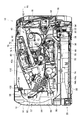
図面を参照して本発明の実施例を説明する。図3は、本実施例のレーザプリンタ10の断面図である。以下では、レーザプリンタ10のことを、プリンタ10と簡単に記述することがある。本実施例では、図3の右方向をプリンタ10の前側とする。
(レーザプリンタの全体構成)
まず、レーザプリンタ10の全体構成を簡単に説明しておく。
(ケーシングの構成)
プリンタ10はケーシング12を有する。ケーシング12は、複数の板状の部材によって構成されている。図3には、ケーシング12の一部を構成する部材として、後側カバー部材14と前側カバー部材16等が示されている。前側カバー部材16は、軸18を中心として矢印R1又はR2方向に揺動可能である。前側カバー部材16が矢印R1方向に揺動すると、ケーシング12が開かれる。この状態では、後述のプロセスカートリッジ40を交換することができる。前側カバー部材16が矢印R2方向に揺動すると、ケーシング12が閉じられる。
(First embodiment)
Embodiments of the present invention will be described with reference to the drawings. FIG. 3 is a cross-sectional view of the
(Whole structure of laser printer)
First, the overall configuration of the
(Structure of casing)
The
プリンタ10は、給紙装置20とプロセスカートリッジ40と露光装置70とトナー定着装置90等を有する。これらの各装置20,40,70,90は、ケーシング12の内部に配置されている。以下では、各装置20,40,70,90について順に説明する。
(給紙装置の構成)
給紙装置20は、給紙トレイ22と4つのローラ28,30,32,34等を備える。給紙トレイ22には、図示省略の印刷用紙が積層される。給紙トレイ22は、積層された印刷用紙が載置される底板24を有する。
給紙ローラ28は反時計回りに回転する。給紙ローラ28が回転すると、給紙トレイ22に収容されている最上位の印刷用紙が右方向に送られる(矢印D1)。右方向に送られた印刷用紙は、ローラ30に接触する。さらに、印刷用紙は、ローラ32,34の間を通過する。ローラ32,34を通過した印刷用紙は、レール36に沿って、2つのレジストローラ38,38の間に送られる。
The
(Configuration of paper feeder)
The
The
下側のレジストローラ38は、反時計回りに回転する。これにより、印刷用紙を矢印D2方向に送ることができる。上側のレジストローラ38は、下側のレジストローラ38によって送られる印刷用紙と接触することによって従動し、時計回りに回転する。
レジストローラ38,38によって印刷用紙が矢印D2方向に送られると、印刷用紙に印字又は描画が印刷される。具体的には、プロセスカートリッジ40と露光装置70と定着装置90によって印刷が行われる。
The
When the printing paper is fed in the direction of the arrow D2 by the
(プロセスカートリッジの構成)
プロセスカートリッジ40は、ケーシング12に対して着脱可能である。前側カバー16を開けると(矢印R1)、プロセスカートリッジ40をケーシング12から取り外すことができる。古いプロセスカートリッジ40を新しいものに交換することができる。
プロセスカートリッジ40の詳しい構成は後で説明する。ここでは簡単に構成を説明しておく。プロセスカートリッジ40はケーシング42を有する。ケーシング42の上面には貫通孔42aが形成されている。ケーシング42の内部の右側には、トナー室45が形成されている。このトナー室45にトナーが収容されている。ケーシング42の内部の左側には、3つのローラ48,50,52と感光体ドラム54が配置されている。これらのローラ48,50,52とドラム54のそれぞれは、図示省略の駆動源に接続されている。最も右方に位置するローラ48を供給ローラと呼ぶ。供給ローラ48の左側には現像ローラ50が配置されている。現像ローラ50の左側には感光体ドラム54が配置されている。感光体ドラム54の下側には転写ローラ52が配置されている。レジストローラ38によって矢印D2方向に送られた印刷用紙は、感光体ドラム54と転写ローラ52の間に入り込む。感光体ドラム54は時計回りに回転するとともに、転写ローラ52は反時計回りに回転する。感光体ドラム54と転写ローラ52が回転することによって、印刷用紙はさらに左方向に送られる(矢印D2)。左方向に送られる過程で、印刷用紙には、感光体ドラム54に付着したトナーが転写される。
(Process cartridge configuration)
The
A detailed configuration of the
(露光装置の構成)
露光装置70は、プロセスカートリッジ40の上方に配置されている。露光装置70は、ケーシング12に固定されている。露光装置70はケーシング72を有する。ケーシング72の下面には、貫通孔72aが形成されている。ケーシング72内には、ポリゴンミラー74と反射鏡76とレンズ78と反射鏡80等を備えている。露光装置70は図示省略の光源を有している。光源からレーザ光線が発光される。光源から供給されたレーザ光線は、ポリゴンミラー74で偏向して反射鏡76に向かう。レーザ光線は反射鏡76で反射してレンズ78を通過する。レンズ78を通過したレーザ光線は反射鏡80でさらに反射する。反射鏡80で反射したレーザ光線は、貫通孔72aからケーシング72外に出て下方に向かう。ケーシング72を飛び出したレーザ光線は、プロセスカートリッジ40の貫通孔42aを通って感光体ドラム54に到達する。これにより、感光体ドラム54が所定のパターンで露光される。図3の矢印Lは、レーザ光線の上記した軌跡を示す。
(Configuration of exposure apparatus)
The
(トナー定着装置の構成)
続いて、トナー定着装置90の構成について説明する。トナー定着装置90は、プロセスカートリッジ40の後方(図3の左側)に配置されている。トナー定着装置90は、フレーム92と加熱ローラ94と加圧ローラ96を備えている。
フレーム92は、加熱ローラ94と加圧ローラ96を回転可能に支持している。加熱ローラ94は、金属管94aと、その内部に配置されているハロゲンランプ94bを有している。ハロゲンランプ94bが金属管94aを加熱する。加熱ローラ94は、時計回りに回転する。加圧ローラ96は、図示省略の機構によって加熱ローラ94側に付勢している。加圧ローラ96は、加熱ローラ94が時計回りに回転すると、従動して反時計回りに回転する。
プロセスカートリッジ40を通過した印刷用紙は、加熱ローラ94と加圧ローラ96の間に入り込む。加熱ローラ94が時計回りに回転すると、加熱ローラ94と加圧ローラ96の間の印刷用紙が左方向に送られる。高温に加熱された加熱ローラ94によって印刷用紙が加熱される。これにより、印刷用紙に転写されたトナーが熱によって定着する。トナー定着装置90を通過した印刷用紙は左上方向に送られる(矢印D3)。
(Configuration of toner fixing device)
Next, the configuration of the
The
The printing paper that has passed through the
(排紙機構の構成)
フレーム92の左端のすぐ下側には、搬送ローラ97が配置されている。搬送ローラ97は、反時計回りに回転する。搬送ローラ97は、トナー定着装置90を経て送られてくる印刷用紙をさらに左上方に送る。搬送ローラ97によって左上方に送られた印刷用紙は、レール98に沿って右方向に送られる(矢印D4)。
レール98の右側には一対の排紙ローラ100,100が配置されている。下側の排紙ローラ100は、時計回りに回転する。下側の排紙ローラ100が時計回りに回転すると、上側の排紙ローラ100が従動して反時計回りに回転する。
搬送ローラ96によって送られてきた印刷用紙は、一対の排紙ローラ100,100の間に入り込む。下側の排紙ローラ100が時計回りに回転すると、2つの排紙ローラ100,100の間の印刷用紙は右方向に送られる。印刷用紙は、ケーシング12の外部に送り出される。ケーシング12の上面には排紙トレイ110が形成されている。ケーシング12の外部に送り出された印刷用紙は、排紙トレイ110の上に排紙される。
(Configuration of paper discharge mechanism)
A
A pair of
The printing paper sent by the
プリンタ10の全体構成を簡単に説明した。続いて、プロセスカートリッジ40の構成を詳しく説明する。
(プロセスカートリッジの詳細な構成)
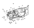
図4は、プロセスカートリッジ40の拡大断面図を示す。プロセスカートリッジ40は、2つのカートリッジ43,44によって構成されている。右側に配置されているカートリッジ43を現像剤カートリッジと呼び、左側に配置されているカートリッジ44を感光体カートリッジと呼ぶ。現像剤カートリッジ43と感光体カートリッジ44は分離可能に接続されている。図5には、現像剤カートリッジ43が分離された後の感光体カートリッジ44の断面図が示されている。このプロセスカートリッジ40によると、現像剤カートリッジ43のみを交換することができるとともに、感光体カートリッジ44のみを交換することもできる。プロセスカートリッジ40の全体を交換することもできる。
The overall configuration of the
(Detailed configuration of process cartridge)
FIG. 4 shows an enlarged cross-sectional view of the
(感光体カートリッジの構成)
感光体カートリッジ44の構成を説明する。感光体カートリッジ44はケーシング44aを有する。このケーシング44aの上面に、レーザ光線が通過する貫通孔42aが形成されている。ケーシング44aの下面には、印刷用紙が入ってくる送入孔44bが形成されている。また、ケーシング44aの左側面には、印刷用紙が出ていく送出孔44cが形成されている。印刷用紙は、送入孔44bから感光体カートリッジ44内に入り、感光体ドラム54と転写ローラ52の間を通過し、送出孔44cから出て行く。
感光体カートリッジ44のケーシング44a内には、感光体ドラム54と転写ローラ52と帯電器66が配置されている。
(Configuration of photoconductor cartridge)
The configuration of the
In the
感光体ドラム54は、現像ローラ50の左側で現像ローラ50に接触している。感光体ドラム54は、ドラム本体54aとドラム軸54bを有している。ドラム本体54aは、円筒形状を有している。ドラム本体54aは、正帯電性の感光体である。ドラム本体54aは、ドラム軸54bに回転可能に取付けられている。ドラム軸54bは、感光体カートリッジ44のケーシング44aに固定されている。ドラム本体54aは、図示省略の駆動源に接続されている。ドラム本体54aは時計回りに回転する。
The
転写ローラ52は、感光体ドラム54の下側で感光体ドラム54に接触している。転写ローラ52は、転写ローラ本体52aと転写ローラ軸52bを備えている。転写ローラ本体52aは、転写ローラ軸52bを覆う円筒形状を有する。転写ローラ軸52bは、感光体カートリッジ44のケーシング44aに回転可能に支持されている。転写ローラ52は、反時計回りに回転する。転写ローラ軸52bは、図示省略の電圧供給回路に接続されている。転写時(感光体ドラム54に付着したトナーを印刷用紙に転写させる時)には、この電圧供給回路から転写ローラ52にバイアスが印加される。
The
帯電器66は、感光体ドラム54の上方に配置されている。帯電器66と感光体ドラム54の間には隙間が設けられている。帯電器66はスコロトンタイプである。帯電器66は、放電ワイヤ66aとグリッド66bを有する。放電ワイヤ66aは、図4の紙面垂直方向に伸びている。放電ワイヤ66aには高電圧が付与される。グリッド66bは、放電ワイヤ66aと感光体ドラム54の間に配置されている。グリッド66bにはバイアス電圧が印加される。これにより、放電ワイヤ66aの放電量を調整する。放電ワイヤ66aに高電圧を印加してコロナ放電させるとともに、グリッド66bにバイアス電圧を印加する。これにより、感光体ドラム54の表面(ドラム本体54a)が正に帯電する。
The
(現像剤カートリッジの構成)
続いて、現像剤カートリッジ43の構成を説明する。現像剤カートリッジ43はケース本体43aを有する。このケース本体43a内にはトナー室45が形成されている。トナー室45は、トナーを収容する。本実施例では、正帯電性の非磁性1成分系のトナーを利用する。例えば、スチレン系単量体やアクリル系単量体を懸濁重合によって共重合させることによって得られた重合トナーを利用する。アクリル系単量体としては、アクリル酸、アルキル(C1〜C4)アクリレート、アルキル(C1〜C4)メタアクリレート等を採用することができる。この重合トナーは、略球形を有し、流動性に優れている。重合トナーには、着色剤やワックスが配合されている。また、流動性を向上させるために、シリカ等の外添剤が添加されている。トナー室45にはアジテータ46が収容されている。アジテータ46は、軸46aを中心として回転可能にケース本体43aに支持されている。アジテータ46が時計回りに回転すると、トナー室45内のトナーが攪拌される。これにより、トナーが供給ローラ48に供給される。
(Configuration of developer cartridge)
Next, the configuration of the
ケース本体43aの左面には開口43bが形成されている。開口43bは、図4の紙面垂直方向に伸びている。開口43bの右側には、供給ローラ48が配置されている。開口43bの左側には、現像ローラ50が配置されている。供給ローラ48と現像ローラ50は、開口43bを臨む位置に配置されている。
供給ローラ48は、供給ローラ本体48aと供給ローラ軸48bと固定部材180(図4では示されていないが図6等に示されている)を備えている。供給ローラ本体48aは、供給ローラ軸48bを覆う円筒形状を有する。供給ローラ本体48aは、導電性の発泡材料によって形成されている。供給ローラ軸48bは、金属製である。供給ローラ軸48bは、現像剤カートリッジ43のケース本体43aに回転可能に支持されている。供給ローラ48は、反時計回りに回転する。固定部材180については、後で詳しく説明する。
An
The
現像ローラ50は、供給ローラ48よりもケース本体43aの外側に位置している。現像ローラ50は、供給ローラ48に強く接触している。現像ローラ50は、現像ローラ本体50aと現像ローラ軸50bを備えている。現像ローラ本体50aは、現像ローラ軸50bを覆う円筒形状を有する。現像ローラ本体50aは、導電性のゴム材料製である。このゴム材料としては、カーボン微粒子等を含む導電性のウレタンゴム又はシリコンゴムを採用することができる。現像ローラ軸50bは、金属製である。現像ローラ軸50bには、図示省略の電圧供給回路が接続されている。現像時(トナーを感光体ドラム54に付着させる時)には、この電圧供給回路から現像ローラ50にバイアスが印加される。現像ローラ軸50bは、ケース本体43aに回転可能に支持されている。現像ローラ50は、反時計回りに回転する。
The developing
ケース本体43aには、層厚規制部材47が固定されている。層厚規制部材47は、開口43bの左側に配置されている。層厚規制部材47は、図4の紙面垂直方向に伸びており、現像ローラ50に接触している。層厚規制部材47は、現像ローラ50の表面に形成されるトナー層の厚みを規制(調整)する。
A layer
図6は、図4のVI方向に見た場合の現像剤カートリッジ43の正面図を簡単に示す。図6は、感光体カートリッジ44を示していない。図6では、現像ローラ50を破線で示している。現像ローラ50は、ケース本体43aの開口43bを臨む位置で左右方向に伸びている。層厚規制部材47は、ケース本体43aの上部に固定されている。層厚規制部材47は左右方向に伸びている。
ケース本体43aの左右の端部には、現像ローラ50の回転面(現像ローラ本体50aの円柱面)に対向する領域140,140が存在する。ケース本体43aの対向領域140,140のそれぞれに、サイドシール部材150,150が取付けられている。
FIG. 6 simply shows a front view of the
At the left and right ends of the case
図7は、現像剤カートリッジ43の右端部(図6の右端部)の付近の斜視図を示す。現像剤カートリッジ43の右端部の構成について詳しく説明する。現像剤カートリッジ43の左端部は、現像剤カートリッジ43の右端部を左右反転したものになるために、それについての詳しい説明を省略する。なお図7では、層厚規制部材47の構成がよくかわるように、後述するフレーム部材160aの一部を切り欠いて示している。
図7では、現像ローラ50を図示省略している。ケース本体43aの右端部には、現像ローラ50を回転可能に支持するための孔部143aが設けられている。現像ローラ軸50b(図4参照)は、孔部143aを越えて外方(図7の右方)に伸びる。
ケース本体43aの下部フレーム43cには、下側シール部材152が接着されている。下側シール部材152は、ケース本体43aの左右方向(図6の左右方向)のほぼ全域に亘って伸びている。図6には、その様子がよく示されている。
FIG. 7 is a perspective view of the vicinity of the right end portion (the right end portion in FIG. 6) of the
In FIG. 7, the developing
A
図8は、図7のVIII−VIII線断面図を示す。図8では、現像ローラ50を破線で示している。破線の矢印は、現像ローラ50の回転方向を示す。
サイドシール部材150の構成を説明する。サイドシール部材150は、2層構造を有している。サイドシール部材150の下層150aは、ケース本体43aの対向領域140(図6参照)に接合されている。この下層150aはスポンジによって構成されている。サイドシール部材150の上層150bは、下層150aに積層されている。この上層150bは、フェルトによって構成されている。上層150bは、現像ローラ50の回転面に接触する。
上層150bは、下層150aを越えて上方に伸びている。下層150aを越えて上方に伸びている部分は、スポンジ層150cに接合されている。
下層150aとスポンジ層150cを弾性変形可能なスポンジで構成することによって、上層150bを現像ローラ50に強く押し当てることができる。これによって、高いシール効果を得ることができる。
8 shows a cross-sectional view taken along line VIII-VIII in FIG. In FIG. 8, the developing
The configuration of the
The
By configuring the
続いて、層厚規制部材47の構成を詳しく説明する。層厚規制部材47は、保持部材160と当接部材162を有する。保持部材160は、当接部材162を保持するものである。当接部材162は、図8の断面図では見えないが、図7に示されている。当接部材162は、現像ローラ50の回転軸方向に伸びており、現像ローラ50の回転軸方向のほぼ全域に亘って当接する。当接部材162はゴム製である。
保持部材160は、2つのフレーム部材160a,160bとステンレス板160cから構成される。前側(図8の左側)のフレーム部材160aは、略L字形状を有している。前側のフレーム部材160aと後側のフレーム部材160bの間にステンレス板160cが挟まれている。2つのフレーム部材160a,160bとステンレス板160cのそれぞれは、現像ローラ50の回転軸方向(図8の紙面垂直方向)に伸びている。図7に示すように、当接部材162は、ステンレス板160cに接合されている。当接部材162は、ステンレス板160cの左右の端部(図6の左右端部)には接合されていない。その端部には、サイドシール部材150(スポンジ層150c及び上層150bの一部)が接合されている。
Next, the configuration of the layer
The holding
ケース本体43aと後側のフレーム部材160bの間には、スポンジ部材164が配置されている。このスポンジ部材164は、現像ローラ50の回転軸方向に伸びている。スポンジ部材164は、ケース本体43aとフレーム部材160bの間をシールする。スポンジ部材164とステンレス板160cの間にもスポンジ部材166が配置されている。このスポンジ部材166も、現像ローラ50の回転軸方向に伸びており、シールとして機能する。
ケース本体43aの下部には、供給ローラ軸48bの周りを埋める弾性部材(例えばスポンジ)168が配置されている。サイドシール部材150は、このスポンジ168にも接合されている。
A
An elastic member (for example, sponge) 168 that fills around the
図7に戻って、供給ローラ48の固定部材180の周辺の構成について説明する。図7に示されるように、供給ローラ48は、固定部材180を有している。供給ローラ本体48aの端面170とケース本体43aの内側面190の間には、隙間G1が形成されている。固定部材180は、その隙間G1を部分的に埋めるようにして配置されている。なお、供給ローラ本体端面170は、フラットに形成されている。
図9は、図7のIX方向に見た場合のケース本体内側面190及びサイドシール部材150を示す。図9では、供給ローラ48を破線で示している。図9に示されるように、供給ローラ本体48aの端面170は、ケース本体内側面190とサイドシール部材150の両者に対向している。また、固定部材180は、現像ローラ50に到達する長さ(供給ローラ本体端面170の半径方向の長さ)を有している。図9の状態では固定部材180と現像ローラ50が接触しているために、固定部材180が撓んでいる。
Returning to FIG. 7, the configuration around the fixing
FIG. 9 shows the case body
図10は、供給ローラ本体48aの端面170を正面視した図を示す。図10に示されるように、供給ローラ軸48bの露出部分(供給ローラ本体48aから突出している部分)は、図10の紙面方向に見ると略D字形状を有している。この様子は、図8にも示されている。供給ローラ軸48bの非露出部分は、円柱形状を有している。
固定部材180は、樹脂製(具体的にはポリプロピレン樹脂)である。固定部材180は、供給ローラ軸48bのD字形状に対応する形状に形成されている部分182と、その部分182から上方に伸びている部分184を有している。固定部材180は、供給ローラ軸48bに部分182が嵌りこむことによって、供給ローラ軸48bに固定されている。
FIG. 10 is a front view of the
The fixing
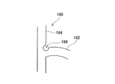
図11は、図10の領域XIの拡大図を示す。部分182と部分184の間には、切り欠き186が形成されている。図11の紙面垂直方向に見た場合、切り欠き186は、略円形状を有している。切り欠き186は、図11の紙面垂直方向の全域に亘って固定部材180に形成されている。この切り欠き186が設けられているために、部分184が図11の右方向(時計回り方向)に容易に撓むことができる。
図10を見るとわかるように、固定部材180の部分184は、供給ローラ軸48bから供給ローラ本体端面170の半径方向外側に向かって伸びる矩形形状を有している。部分184は、供給ローラ本体端面170を超えて外側(図10の状態では上方)に伸びている。固定部材180は、供給ローラ48が回転しても層厚規制部材47(図7参照)に接触しない長さ(供給ローラ本体端面170の半径方向の長さ)を有している。一方において、固定部材180は、供給ローラ48の回転中に現像ローラ50や下部フレーム43cに接触する長さを有している。固定部材180が現像ローラ50等に接触して容易に撓むことができるように、固定部材180に切り欠き186(図11参照)が設けられている。固定部材180は、現像ローラ50や下部フレーム43cに接触すると部分184が撓む。
固定部材180は、供給ローラ本体端面170とケース本体内側面190(図7参照)の間の距離と同じ幅(図6の左右方向の幅)を有している。即ち、固定部材180は、供給ローラ本体端面170に接触しているとともに、ケース本体内側面190に接触している。また、固定部材180は、サイドシール部材150の上層150b及び下層150aに接触している。
FIG. 11 shows an enlarged view of region XI in FIG. A
As can be seen from FIG. 10, the
The fixing
(プロセスカートリッジの作用)
プロセスカートリッジ40の構成について詳細に説明した。続いて、再び図4を参照して、上記した構成を有するプロセスカートリッジ40の作用について説明する。
トナー室45のトナーは供給ローラ48に付着する。供給ローラ48に付着しているトナーは、供給ローラ48と現像ローラ50の間の摩擦によって正に帯電する。正に帯電しているトナーが現像ローラ50の表面を覆う。現像ローラ50の表面のトナー層には、層厚規制部材47の当接部材162(図7参照)が当接する。これにより、トナー層が一定の厚みに調整される。
一方において、ドラム本体54aの表面は、帯電器66によって正に帯電している。正に帯電しているドラム本体54aの表面は、露光装置70(図3参照)から発光されたレーザ光線を受光する。これにより、ドラム本体54aの表面の所定部分が露光される。ドラム本体54aの露光部分は電位が下がる。どの部分が露光されるのかは、印刷内容によって変わる。印刷内容に基づいた静電潜像がドラム本体54aに形成される。
現像ローラ50を被覆しているトナーは、ドラム本体54aの露光部分に付着する。このとき、ドラム本体54aの非露光部分にはトナーが付着しない。これにより、ドラム本体54aに形成されている静電潜像が可視像化する。
ドラム本体54aに担持されている可視像は、感光体ドラム54と転写ローラ52の間の印刷用紙に転写される。このとき、転写ローラ52にはバイアスが印加される。感光体ドラム54と転写ローラ52の間の電位差によってトナーが印刷用紙に転写する。
上記した各プロセスを経ることによって、所望の画像(印字や描画)が印刷用紙に印刷される。
(Operation of process cartridge)
The configuration of the
The toner in the
On the other hand, the surface of the
The toner covering the developing
The visible image carried on the
A desired image (printing or drawing) is printed on the printing paper through the above-described processes.
本実施例では、供給ローラ本体端面170とケース本体内側面190の間に隙間G1が設けられている(図7参照)。供給ローラ本体48aから回転軸方向に向かって移動するトナーは、隙間G1に入り込む。隙間G1が設けられているために、供給ローラ本体48aからケース本体内側面190に直接的にトナーが移動することを抑制することができる。
供給ローラ48は、その隙間G1を部分的に埋める固定部材180を有している。固定部材180は、供給ローラ軸48bと一体になって回転する。これにより、固定部材180は、隙間G1に入り込んだトナーを掻き取る。
図7や図10から明らかなように、固定部材180は、隙間G1の容積と比べると非常に小さい容積に構成されている。固定部材180の容積は、隙間G1の容積の少なくとも半分以下である。固定部材180の容積が小さいために、隙間G1の容積が大きく確保されている。
固定部材180は、供給ローラ本体端面170からケース本体内側面190まで伸びている。また固定部材180は、供給ローラ軸48bから供給ローラ本体端面170を超えて外側に伸びている。これらの構成を有しているために、回転中の固定部材180は、隙間G1の全域を通過することができる。従って、固定部材180は、隙間G1の全域に亘ってトナーを掻き取ることができる。
固定部材180を設けないと、隙間G1の中にトナーが溜まっていく。この場合、隙間G1に溜まったトナーが、サイドシール部材150と現像ローラ50の間の僅かな隙間G2(図9参照)に入り込んでしまう。この隙間G2の中をトナーが移動すると、ケース本体43aからトナーが漏れることがある。本実施例では、固定部材180を設けているために、隙間G1にトナーが溜まらない。ケース本体内側面190の近くにトナーが留まることを防止することができる。隙間G2にトナーが入り込むことを防止することができる。
また、図9に示されるように、固定部材180は、サイドシール部材150の上層150bに到達する長さ(供給ローラ本体端面170の半径方向の長さ)を有している。このため、固定部材180は、上層150bの側面に付着するトナーを掻き取ることができる。また、固定部材180は、現像ローラ50に接触する長さを有している。固定部材180は、現像ローラ50に接触すると撓む。固定部材180は、撓みながら回転することによって、現像ローラ50に対するサイドシール部材150の接触面とサイドシール部材150の側面との間のエッジ部に付着しているトナーをうまく掻き取ることができる。固定部材180は、サイドシール部材150の上層150bと現像ローラ50の間に入り込もうとするトナーを掻き取ることができる。
本実施例の技術によると、現像カートリッジ43からトナーが漏れる事象を効果的に抑制することができる。
In the present embodiment, a gap G1 is provided between the supply roller main
The
As is apparent from FIGS. 7 and 10, the fixing
The fixing
If the fixing
9, the fixing
According to the technique of this embodiment, it is possible to effectively suppress the phenomenon of toner leakage from the developing
(第2実施例)
図12は、第2実施例の供給ローラ48を示す。ここでは、第1実施例と異なる部分のみを説明する。
本実施例の固定部材210は、供給ローラ軸48bの周りに固定される部分212と、部分212から上方に伸びている部分214を有する。部分212は、第1実施例と同じ構成を有する。部分214の上端部は、図12の右方向(時計回り方向)に予め撓んでいる。この点が第1実施例と異なる。部分214は、供給ローラ48の反回転方向に曲がっている。
本実施例のように固定部材210を予め撓ませておいても、現像ローラ50に対するサイドシール部材150の接触面とサイドシール部材150の側面との間のエッジ部に付着しているトナーをうまく掻き取ることができる。
(Second embodiment)
FIG. 12 shows the
The fixing
Even if the fixing
(第3実施例)
図13は、第3実施例の現像剤カートリッジ43の一部の正面図を示す。ここでは、第1実施例と異なる部分のみを説明する。
本実施例では、層厚規制部材47の構成が第1実施例と異なる。ステンレス板160cと当接部材162には、切り欠き250が形成されている。切り欠き250は、図示省略の現像ローラ50の回転軸方向の端部(図13の右端部)に対応する位置に設けられている。この構成によると、現像ローラ50に対する当接部材162の接触面積が、切り欠き250以外の部分では大きくなり、切り欠き250の部分では小さくなる。接触面積が大きいと、当接部材162から現像ローラ50に対して小さい圧力が加えられ、現像ローラ50のトナー層が厚くなる。接触面積が小さいと、当接部材162から現像ローラ50に対して大きい圧力が加えられ、現像ローラ50のトナー層が薄くなる。
切り欠き250は、現像ローラ50の回転軸方向の端部に対応する位置に設けられている。このために、現像ローラ50の回転軸方向の端部は、トナー層が薄くなる。現像ローラ50の回転軸方向の端部は、ケース本体43aの内側面190(図7参照)の近くにある。この構成によると、ケース本体内側面190の近くでは現像ローラ50のトナー層を薄くすることができる。
ケース本体内側面190の近くに多くのトナーが存在すると、ケース本体内側面190からトナーが漏れる可能性が高くなる。本実施例の構成によると、ケース本体内側面190の近くでは現像ローラ50のトナー層を薄くすることができる。ケース本体内側面190の近くに多くのトナーが存在する状態を避けることができる。
上記の構成では、切り欠き250にトナーが入り込むことがある。切り欠き250にトナーが入り込むと、ケース本体内側面190の近くにトナーが留まることになる。この場合、トナー漏れが起こり易くなる。これを避けるために、本実施例の固定部材280は、供給ローラ48の回転中に切り欠き250に侵入する長さを有する。図13では、固定部材280が切り欠き250に侵入している状態が示されている。
本実施例によると、固定部材280が切り欠き250に侵入することによって、切り欠き250に入り込んだトナーを掻き取ることができる。トナー漏れを効果的に抑制することができる。
(Third embodiment)
FIG. 13 is a front view of a part of the
In the present embodiment, the configuration of the layer
The
If a large amount of toner is present near the
In the above configuration, toner may enter the
According to this embodiment, when the fixing
(第4実施例)
図14は、第4実施例の供給ローラ48の一部の斜視図を示す。ここでは、第1実施例と異なる部分のみを説明する。
上記の第1実施例では、固定部材180(図7等参照)が、供給ローラ本体48aと別体に構成されている。これに対し、本実施例の固定部材380a,380bは、供給ローラ本体48aと一体に構成されている。供給ローラ本体48aと固定部材380a,380bは、素材(発泡材料)を切削加工することによって形成される。
固定部材380a,380bの厚みG3は、供給ローラ本体端面170とケース本体内側面190(図7参照)の間の距離に等しい。即ち、固定部材380a,380bは、ケース本体内側面190とサイドシール部材150に接触する。
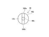
本実施例では、一対の固定部材380a,380bが、供給ローラ軸48bを中心に対称に設けられている。図15には、図14のXV方向に見た図を示す。図15に示されるように、各固定部材380a,380bは、供給ローラ軸48bから半径方向外側に向かって伸びる矩形形状を有している。
本実施例を採用すると、供給ローラ本体48aと固定部材380a,380bを1つの素材から形成することができる。現像カートリッジ43を構成するために必要な素材の種類の数を減らすことができる。
(Fourth embodiment)
FIG. 14 is a perspective view of a part of the
In the first embodiment, the fixing member 180 (see FIG. 7 and the like) is configured separately from the supply roller
The thickness G3 of the fixing
In this embodiment, the pair of fixing
When this embodiment is adopted, the supply roller
以上、本発明の具体例を詳細に説明したが、これらは例示にすぎず、特許請求の範囲を限定するものではない。特許請求の範囲に記載の技術には、以上に例示した具体例を様々に変形、変更したものが含まれる。
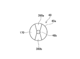
(1)固定部材の形状は変更することができる。例えば、図16のような形状を採用することができる。図16は、本変形例の供給ローラ本体端面170を正面視したときの図を示す。図16に示されるように、固定部材390a,390bは、供給ローラ軸48bから半径方向外側に向かうにつれて広がる扇形形状を有していてもよい。
(2)また例えば、図17のような形状を採用することもできる。図17は、本変形例の供給ローラ本体端面170を正面視したときの図を示す。この変形例の固定部材400a〜400fは、供給ローラ軸48bから半径方向外側に向けて放射状に伸びている羽根形状を有する。この形状を採用すると、トナーを効果的に掻き取ることができる。
(3)固定部材の材料は、樹脂以外の材料に変更することができる。例えばPET等を採用することができる。また例えば、固定部材は、サイドシール部材150の上層150bと同じフェルトによって構成されてもよい。この場合、サイドシール部材150の上層150bと固定部材を同じ素材から形成することができる。現像剤カートリッジ43を構成するために必要な素材の種類の数を減らすことができる。
(4)固定部材の寸法は変更することができる。例えば、固定部材は、供給ローラ本体48aに接触していなくてもよい。また、固定部材は、ケース本体内側面190に接触していなくてもよい。また、固定部材は、供給ローラ本体端面170を超えなくてもよい。例えば、固定部材は、供給ローラ本体端面170の半径よりも短い長さであってもよい。
Specific examples of the present invention have been described in detail above, but these are merely examples and do not limit the scope of the claims. The technology described in the claims includes various modifications and changes of the specific examples illustrated above.
(1) The shape of the fixing member can be changed. For example, a shape as shown in FIG. 16 can be adopted. FIG. 16 is a diagram when the supply roller main
(2) Further, for example, a shape as shown in FIG. 17 may be employed. FIG. 17 shows a view when the supply roller main
(3) The material of the fixing member can be changed to a material other than resin. For example, PET or the like can be employed. Further, for example, the fixing member may be configured by the same felt as the
(4) The dimension of the fixing member can be changed. For example, the fixing member may not be in contact with the supply roller
また、本明細書または図面に説明した技術要素は、単独であるいは各種の組合せによって技術的有用性を発揮するものであり、出願時請求項記載の組合せに限定されるものではない。また、本明細書または図面に例示した技術は複数目的を同時に達成するものであり、そのうちの一つの目的を達成すること自体で技術的有用性を持つものである。 The technical elements described in this specification or the drawings exhibit technical usefulness alone or in various combinations, and are not limited to the combinations described in the claims at the time of filing. In addition, the technology illustrated in the present specification or the drawings achieves a plurality of objects at the same time, and has technical utility by achieving one of the objects.
10:レーザプリンタ
20:給紙装置
40:プロセスカートリッジ
45:トナー室
47:層厚規制部材
48:供給ローラ
48a:供給ローラ本体
48b:供給ローラ軸
50:現像ローラ
52:転写ローラ
54:感光体ドラム
66:帯電器
70:露光装置
90:定着装置
150:サイドシール部材
170:供給ローラ本体端面
180:固定部材
190:ケース本体内側面
10: Laser printer 20: Paper feeding device 40: Process cartridge 45: Toner chamber 47: Layer thickness regulating member 48:
Claims (15)
ケース本体と、ケース本体に回転可能に支持されている第1ローラを備え、
第1ローラは、回転軸と、回転軸を覆う円筒形状のローラ本体と、回転軸及び/又はローラ本体に固定されている固定部材を有し、
ローラ本体の端面とケース本体の内側面の間に隙間が設けられており、
固定部材は、前記隙間を部分的に埋めることを特徴とする現像剤収容ケース。 A developer storage case for storing the developer;
A case body and a first roller rotatably supported by the case body;
The first roller has a rotation shaft, a cylindrical roller body covering the rotation shaft, and a fixing member fixed to the rotation shaft and / or the roller body.
A gap is provided between the end surface of the roller body and the inner surface of the case body,
The developer storage case, wherein the fixing member partially fills the gap.
第2ローラは、第1ローラよりもケース本体の外側で第1ローラに接触しており、
ケース本体は、第2ローラの回転軸方向の端部においてその回転面に対向する領域を有しており、
サイドシール部材は、前記対向領域に配置されているとともに、第2ローラに接触しており、
第1ローラのローラ本体の端面は、ケース本体とサイドシール部材の両者に対向していることを特徴とする請求項1から11のいずれかの現像剤収容ケース。 A second roller rotatably supported by the case body, and a side seal member fixed to the case body,
The second roller is in contact with the first roller on the outer side of the case body than the first roller,
The case main body has a region facing the rotation surface at the end of the second roller in the rotation axis direction,
The side seal member is disposed in the facing region and is in contact with the second roller,
The developer containing case according to any one of claims 1 to 11, wherein an end surface of the roller body of the first roller faces both the case body and the side seal member.
第1層は、弾性素材によって形成されており、
第2層は、繊維素材によって形成されていることを特徴とする請求項12の現像剤収容ケース。 The side seal member has a first layer fixed to the case main body, and a second layer laminated on the first layer and in contact with the second roller,
The first layer is formed of an elastic material,
The developer storage case according to claim 12, wherein the second layer is made of a fiber material.
層厚規制部材の所定位置に切り欠きが設けられており、
その所定位置は、第2ローラの回転軸方向の端部に対応する位置であり、
固定部材は、第1ローラの回転中に前記切り欠きに侵入する長さを有することを特徴とする請求項12から14のいずれかの現像剤収容ケース。 A layer thickness regulating member that is fixed to the case body, is in contact with the second roller and regulates the thickness of the developer carried by the second roller;
A notch is provided at a predetermined position of the layer thickness regulating member,
The predetermined position is a position corresponding to the end of the second roller in the rotation axis direction,
The developer storage case according to claim 12, wherein the fixing member has a length that enters the notch during rotation of the first roller.
Priority Applications (2)
| Application Number | Priority Date | Filing Date | Title |
|---|---|---|---|
| JP2006016495A JP2007199280A (en) | 2006-01-25 | 2006-01-25 | Developer storage case |
| US11/528,687 US7627264B2 (en) | 2005-09-30 | 2006-09-28 | Developing device and image forming apparatus |
Applications Claiming Priority (1)
| Application Number | Priority Date | Filing Date | Title |
|---|---|---|---|
| JP2006016495A JP2007199280A (en) | 2006-01-25 | 2006-01-25 | Developer storage case |
Publications (1)
| Publication Number | Publication Date |
|---|---|
| JP2007199280A true JP2007199280A (en) | 2007-08-09 |
Family
ID=38453964
Family Applications (1)
| Application Number | Title | Priority Date | Filing Date |
|---|---|---|---|
| JP2006016495A Pending JP2007199280A (en) | 2005-09-30 | 2006-01-25 | Developer storage case |
Country Status (1)
| Country | Link |
|---|---|
| JP (1) | JP2007199280A (en) |
Cited By (3)
| Publication number | Priority date | Publication date | Assignee | Title |
|---|---|---|---|---|
| JP2009180772A (en) * | 2008-01-29 | 2009-08-13 | Brother Ind Ltd | Development device |
| JP2011242608A (en) * | 2010-05-18 | 2011-12-01 | Canon Inc | Developing device |
| JP2020204694A (en) * | 2019-06-17 | 2020-12-24 | 株式会社ブリヂストン | Paint composition for conductive roller, developing roller using the same, and image forming apparatus |
-
2006
- 2006-01-25 JP JP2006016495A patent/JP2007199280A/en active Pending
Cited By (4)
| Publication number | Priority date | Publication date | Assignee | Title |
|---|---|---|---|---|
| JP2009180772A (en) * | 2008-01-29 | 2009-08-13 | Brother Ind Ltd | Development device |
| JP2011242608A (en) * | 2010-05-18 | 2011-12-01 | Canon Inc | Developing device |
| JP2020204694A (en) * | 2019-06-17 | 2020-12-24 | 株式会社ブリヂストン | Paint composition for conductive roller, developing roller using the same, and image forming apparatus |
| JP7270476B2 (en) | 2019-06-17 | 2023-05-10 | 株式会社アーケム | COATING COMPOSITION FOR CONDUCTIVE ROLLER, DEVELOPING ROLLER USING THE SAME, AND IMAGE FORMING APPARATUS |
Similar Documents
| Publication | Publication Date | Title |
|---|---|---|
| US7215902B2 (en) | Developing cartridge, process cartridge, image forming device, and sliding sealing element | |
| JP4736675B2 (en) | Developer housing case, process cartridge having the same, and image forming apparatus | |
| CN1932670B (en) | Image forming unit and image forming apparatus | |
| JP5151302B2 (en) | Developing device, process cartridge, image forming apparatus | |
| JP2017107040A (en) | Developing device and image forming apparatus | |
| JP4356674B2 (en) | Developer housing case, process cartridge having the same, and image forming apparatus | |
| JP3571873B2 (en) | Toner conveying blade and toner supply container | |
| CN115248545B (en) | Developing device and image forming apparatus including the same | |
| JP2006208837A (en) | Developer cartridge and reproducing method thereof | |
| JP7625956B2 (en) | Developing device and image forming apparatus equipped with same | |
| JP4356673B2 (en) | Developer housing case, process cartridge having the same, and image forming apparatus | |
| JP4635701B2 (en) | Developing cartridge, process cartridge, and image forming apparatus | |
| JP2007199280A (en) | Developer storage case | |
| JP6066639B2 (en) | Developing device and process cartridge | |
| JP2007033468A (en) | Image forming apparatus | |
| JP4448122B2 (en) | Developing device and process cartridge | |
| JP6406980B2 (en) | Developing device and process cartridge | |
| US7627264B2 (en) | Developing device and image forming apparatus | |
| JP7585950B2 (en) | Developing device and image forming apparatus equipped with same | |
| JP4501468B2 (en) | Developing device, image forming apparatus, and image forming system | |
| JP4655631B2 (en) | Developing device, image forming apparatus, and image forming system | |
| JP6033596B2 (en) | Image forming apparatus and toner supply device | |
| JP6213237B2 (en) | Development device | |
| JP2011158846A (en) | Developing apparatus and process cartridge | |
| JP2008216636A (en) | Developing device and image forming apparatus equipped therewith |
Legal Events
| Date | Code | Title | Description |
|---|---|---|---|
| A977 | Report on retrieval |
Free format text: JAPANESE INTERMEDIATE CODE: A971007 Effective date: 20081121 |
|
| A131 | Notification of reasons for refusal |
Free format text: JAPANESE INTERMEDIATE CODE: A131 Effective date: 20081202 |
|
| A02 | Decision of refusal |
Free format text: JAPANESE INTERMEDIATE CODE: A02 Effective date: 20090331 |