JP2007247902A - 流体動圧ベアリングの流体充填装置及び充填方法 - Google Patents
流体動圧ベアリングの流体充填装置及び充填方法 Download PDFInfo
- Publication number
- JP2007247902A JP2007247902A JP2007065528A JP2007065528A JP2007247902A JP 2007247902 A JP2007247902 A JP 2007247902A JP 2007065528 A JP2007065528 A JP 2007065528A JP 2007065528 A JP2007065528 A JP 2007065528A JP 2007247902 A JP2007247902 A JP 2007247902A
- Authority
- JP
- Japan
- Prior art keywords
- fluid
- storage tank
- dynamic pressure
- filling
- pressure bearing
- Prior art date
- Legal status (The legal status is an assumption and is not a legal conclusion. Google has not performed a legal analysis and makes no representation as to the accuracy of the status listed.)
- Granted
Links
Images





Classifications
-
- G—PHYSICS
- G10—MUSICAL INSTRUMENTS; ACOUSTICS
- G10G—REPRESENTATION OF MUSIC; RECORDING MUSIC IN NOTATION FORM; ACCESSORIES FOR MUSIC OR MUSICAL INSTRUMENTS NOT OTHERWISE PROVIDED FOR, e.g. SUPPORTS
- G10G5/00—Supports for musical instruments
- G10G5/005—Supports for musical instruments while playing, e.g. cord, strap or harness
-
- F—MECHANICAL ENGINEERING; LIGHTING; HEATING; WEAPONS; BLASTING
- F16—ENGINEERING ELEMENTS AND UNITS; GENERAL MEASURES FOR PRODUCING AND MAINTAINING EFFECTIVE FUNCTIONING OF MACHINES OR INSTALLATIONS; THERMAL INSULATION IN GENERAL
- F16C—SHAFTS; FLEXIBLE SHAFTS; ELEMENTS OR CRANKSHAFT MECHANISMS; ROTARY BODIES OTHER THAN GEARING ELEMENTS; BEARINGS
- F16C17/00—Sliding-contact bearings for exclusively rotary movement
- F16C17/10—Sliding-contact bearings for exclusively rotary movement for both radial and axial load
-
- F—MECHANICAL ENGINEERING; LIGHTING; HEATING; WEAPONS; BLASTING
- F16—ENGINEERING ELEMENTS AND UNITS; GENERAL MEASURES FOR PRODUCING AND MAINTAINING EFFECTIVE FUNCTIONING OF MACHINES OR INSTALLATIONS; THERMAL INSULATION IN GENERAL
- F16C—SHAFTS; FLEXIBLE SHAFTS; ELEMENTS OR CRANKSHAFT MECHANISMS; ROTARY BODIES OTHER THAN GEARING ELEMENTS; BEARINGS
- F16C33/00—Parts of bearings; Special methods for making bearings or parts thereof
- F16C33/02—Parts of sliding-contact bearings
- F16C33/04—Brasses; Bushes; Linings
- F16C33/06—Sliding surface mainly made of metal
- F16C33/10—Construction relative to lubrication
- F16C33/1025—Construction relative to lubrication with liquid, e.g. oil, as lubricant
- F16C33/103—Construction relative to lubrication with liquid, e.g. oil, as lubricant retained in or near the bearing
-
- F—MECHANICAL ENGINEERING; LIGHTING; HEATING; WEAPONS; BLASTING
- F16—ENGINEERING ELEMENTS AND UNITS; GENERAL MEASURES FOR PRODUCING AND MAINTAINING EFFECTIVE FUNCTIONING OF MACHINES OR INSTALLATIONS; THERMAL INSULATION IN GENERAL
- F16C—SHAFTS; FLEXIBLE SHAFTS; ELEMENTS OR CRANKSHAFT MECHANISMS; ROTARY BODIES OTHER THAN GEARING ELEMENTS; BEARINGS
- F16C33/00—Parts of bearings; Special methods for making bearings or parts thereof
- F16C33/02—Parts of sliding-contact bearings
- F16C33/04—Brasses; Bushes; Linings
- F16C33/06—Sliding surface mainly made of metal
- F16C33/10—Construction relative to lubrication
- F16C33/1025—Construction relative to lubrication with liquid, e.g. oil, as lubricant
- F16C33/106—Details of distribution or circulation inside the bearings, e.g. details of the bearing surfaces to affect flow or pressure of the liquid
- F16C33/107—Grooves for generating pressure
-
- G—PHYSICS
- G10—MUSICAL INSTRUMENTS; ACOUSTICS
- G10D—STRINGED MUSICAL INSTRUMENTS; WIND MUSICAL INSTRUMENTS; ACCORDIONS OR CONCERTINAS; PERCUSSION MUSICAL INSTRUMENTS; AEOLIAN HARPS; SINGING-FLAME MUSICAL INSTRUMENTS; MUSICAL INSTRUMENTS NOT OTHERWISE PROVIDED FOR
- G10D13/00—Percussion musical instruments; Details or accessories therefor
-
- F—MECHANICAL ENGINEERING; LIGHTING; HEATING; WEAPONS; BLASTING
- F16—ENGINEERING ELEMENTS AND UNITS; GENERAL MEASURES FOR PRODUCING AND MAINTAINING EFFECTIVE FUNCTIONING OF MACHINES OR INSTALLATIONS; THERMAL INSULATION IN GENERAL
- F16C—SHAFTS; FLEXIBLE SHAFTS; ELEMENTS OR CRANKSHAFT MECHANISMS; ROTARY BODIES OTHER THAN GEARING ELEMENTS; BEARINGS
- F16C2370/00—Apparatus relating to physics, e.g. instruments
- F16C2370/12—Hard disk drives or the like
Landscapes
- Engineering & Computer Science (AREA)
- General Engineering & Computer Science (AREA)
- Mechanical Engineering (AREA)
- Chemical & Material Sciences (AREA)
- Oil, Petroleum & Natural Gas (AREA)
- Physics & Mathematics (AREA)
- Acoustics & Sound (AREA)
- Multimedia (AREA)
- Sliding-Contact Bearings (AREA)
- Mounting Of Bearings Or Others (AREA)
- Magnetic Bearings And Hydrostatic Bearings (AREA)
Abstract
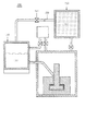
【解決手段】流体を貯蔵するための流体貯蔵タンク110と、流体動圧ベアリング10を収容するための真空容器130と、流体貯蔵タンク110と真空容器130を連結し、流体動圧ベアリング10の微少隙間13に流体を滴下するための流体ディスペンサ140と、流体貯蔵タンク110及び真空容器130に連結され、内部空気を別に排出するためのポンプ160と、流体貯蔵タンク110及び真空容器130を別に加圧するための窒素貯蔵タンク150とを含み、流体貯蔵タンク110は真空容器130より高い圧力の窒素で加圧されることにより、流体が流体ディスペンサ140を通じて、真空容器130に収容された流体動圧ベアリング10に移動して滴下する。
【選択図】図1
Description
110 流体貯蔵タンク
111 流体
120 超音波発生器
130 真空容器
140 流体ディスペンサ
150 窒素貯蔵タンク
151 窒素
160 ポンプ
Claims (11)
- 充填物を貯蔵するための貯蔵手段;
前記充填物が移動するように前記貯蔵手段に連結され、被充填物を収容するための収容手段;
前記貯蔵手段及び前記収容手段に連結され、内部空気を別に排出するための排気手段;及び
前記貯蔵手段及び前記収容手段を別に加圧するための加圧手段を含み、
前記貯蔵手段は前記収容手段より高い圧力で加圧されることにより、前記充填物が前記収容手段に収容された前記被充填物に移動して滴下することを特徴とする、流体動圧ベアリングの流体充填装置。 - 前記加圧手段は、前記貯蔵手段及び前記収容手段に窒素を注入して加圧することを特徴とする、請求項1に記載の流体充填装置。
- 前記充填物に含有された気泡を除去するために、前記貯蔵手段に振動を加えるための加振手段をさらに含むことを特徴とする、請求項2に記載の流体充填装置。
- 流体を貯蔵するための流体貯蔵タンク;
流体動圧ベアリングを収容するための真空容器;
前記流体貯蔵タンクと前記真空容器を連結し、前記流体動圧ベアリングの微少隙間に前記流体を滴下するための流体ディスペンサ;
前記流体貯蔵タンク及び前記真空容器に連結され、内部空気を別に排出するためのポンプ;及び
前記流体貯蔵タンク及び前記真空容器を別に加圧するための窒素貯蔵タンクを含み、
前記流体貯蔵タンクは前記真空容器より高い圧力の窒素で加圧されることにより、前記流体が前記流体ディスペンサを通じて、前記真空容器に収容された前記流体動圧ベアリングに移動して滴下することを特徴とする、流体動圧ベアリングの流体充填装置。 - 前記流体に含有された気泡を除去するために、前記流体貯蔵タンクに超音波を加えるための超音波発生器をさらに含むことを特徴とする、請求項4に記載の流体充填装置。
- 前記ポンプは別途の排気管を介して前記流体貯蔵タンク及び前記真空容器に連結され、前記排気管は開閉のためのスロットルバルブを備えることを特徴とする、請求項4に記載の流体充填装置。
- 前記窒素貯蔵タンクは別途の窒素供給管を介して前記流体貯蔵タンク及び前記真空容器に連結され、前記窒素供給管は開閉のためのスロットルバルブを備えることを特徴とする、請求項4ないし6のいずれか1項に記載の流体充填装置。
- 前記流体動圧ベアリングに滴下した前記流体は、前記窒素貯蔵タンクから供給される前記窒素によって加圧されることにより前記流体動圧ベアリングの前記微少隙間に充填されることを特徴とする、請求項4ないし6のいずれか1項に記載の流体充填装置。
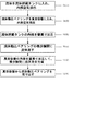
- (A)ポンプを使用して流体貯蔵タンクの内部空気を排出する段階;
(B)真空容器に流体動圧ベアリングを入れ、ポンプを使用して前記真空容器の内部空気を排出する段階;
(C)前記真空容器より圧力が高くなるように、前記流体貯蔵タンクに窒素を注入する段階;
(D)前記流体貯蔵タンクの高圧力を利用して、前記流体を前記流体動圧ベアリングに移動させて滴下させる段階;及び
(E)前記真空容器に窒素を注入して、前記滴下した流体を加圧して充填する段階を含むことを特徴とする、流体動圧ベアリングの流体充填方法。 - 前記(A)段階で、前記内部空気が排出される時、前記流体が振動されることにより、前記流体に含有された気泡が排出されることを特徴とする、請求項9に記載の流体充填方法。
- 前記(D)段階で、前記滴下した流体の一部は毛細管現象によって前記微少隙間に染み込み、残りは前記(E)段階で前記窒素によって加圧されて充填されることを特徴とする、請求項10に記載の流体充填方法。
Applications Claiming Priority (1)
| Application Number | Priority Date | Filing Date | Title |
|---|---|---|---|
| KR1020060024362A KR100807479B1 (ko) | 2006-03-16 | 2006-03-16 | 유체동압베어링의 유체충전장치 및 충전방법 |
Publications (2)
| Publication Number | Publication Date |
|---|---|
| JP2007247902A true JP2007247902A (ja) | 2007-09-27 |
| JP4422737B2 JP4422737B2 (ja) | 2010-02-24 |
Family
ID=38557086
Family Applications (1)
| Application Number | Title | Priority Date | Filing Date |
|---|---|---|---|
| JP2007065528A Expired - Fee Related JP4422737B2 (ja) | 2006-03-16 | 2007-03-14 | 流体動圧ベアリングの流体充填装置及び充填方法 |
Country Status (4)
| Country | Link |
|---|---|
| US (1) | US7694699B2 (ja) |
| JP (1) | JP4422737B2 (ja) |
| KR (1) | KR100807479B1 (ja) |
| CN (1) | CN100494711C (ja) |
Families Citing this family (7)
| Publication number | Priority date | Publication date | Assignee | Title |
|---|---|---|---|---|
| JP4977150B2 (ja) * | 2009-02-04 | 2012-07-18 | アルファナテクノロジー株式会社 | 流体動圧軸受の製造方法 |
| JP5020990B2 (ja) * | 2009-04-07 | 2012-09-05 | アルファナテクノロジー株式会社 | 流体動圧軸受の製造方法および製造装置 |
| DE102012201721A1 (de) * | 2012-02-06 | 2013-08-08 | Schaeffler Technologies AG & Co. KG | Verfahren zum Betrieb einer Wälzlageranordnung und Wälzlagereinrichtung hierzu |
| AT518293B1 (de) * | 2016-02-26 | 2018-05-15 | Minebea Mitsumi Inc | Verfahren zum Befüllen eines fluiddynamischen Lagers mit einem Lagerfluid |
| CN105887198B (zh) * | 2016-06-16 | 2019-01-11 | 江苏振华新云电子有限公司 | 一种清除蓝宝石晶体熔体料中气泡装置及清除方法 |
| CN105865972A (zh) * | 2016-06-22 | 2016-08-17 | 奇瑞汽车股份有限公司 | 一种发动机机油含气量测量设备及其测量方法 |
| CN115614024B (zh) * | 2022-11-07 | 2024-09-06 | 贝兹维仪器(苏州)有限公司 | 一种随钻测井仪密封油填充装置 |
Family Cites Families (17)
| Publication number | Priority date | Publication date | Assignee | Title |
|---|---|---|---|---|
| JPS61128506A (ja) | 1984-11-28 | 1986-06-16 | Mitsubishi Electric Corp | 油入電気機器 |
| US5112142A (en) * | 1987-08-12 | 1992-05-12 | Digital Equipment Corporation | Hydrodynamic bearing |
| US5778948A (en) * | 1994-06-29 | 1998-07-14 | Sankyo Seiki Mfg. Co., Ltd. | Method for inserting a fluid in a bearing device |
| US5601125A (en) * | 1995-07-18 | 1997-02-11 | Seagate Technology, Inc. | Vacuum fill technique for hydrodynamic bearing |
| US5862841A (en) * | 1997-02-20 | 1999-01-26 | Seagate Technology, Inc. | Apparatus for filling a hydrodynamic bearing |
| JPH1140391A (ja) | 1997-07-22 | 1999-02-12 | Toshiba Corp | X線管装置の製造方法およびその製造装置 |
| KR100357638B1 (ko) | 1999-08-31 | 2002-10-25 | 삼성전자 주식회사 | 실리카 솔의 초음파 분산 장치 |
| JP2001165153A (ja) | 1999-12-09 | 2001-06-19 | Citizen Watch Co Ltd | 作動流体注入方法及び作動流体注入装置 |
| US7048444B2 (en) * | 2001-11-13 | 2006-05-23 | Ntn Corporation | Fluid lubricated bearing device |
| US6804987B2 (en) * | 2002-01-03 | 2004-10-19 | Seagate Technology Llc | Apparatus and method for air-contamination detection in disc drive hydrodynamic bearings |
| US6938124B2 (en) | 2002-07-19 | 2005-08-30 | Hewlett-Packard Development Company, L.P. | Hardware assisted communication between processors |
| JP2004176796A (ja) | 2002-11-26 | 2004-06-24 | Tokyo Electric Power Co Inc:The | 潤滑状態管理システム |
| US7344002B2 (en) * | 2003-03-31 | 2008-03-18 | Minebea Co., Ltd. | Method and apparatus for filling the bearing gap of a hydrodynamic bearing with a lubricant |
| JP2005036974A (ja) | 2003-07-02 | 2005-02-10 | Nippon Densan Corp | 流体動圧軸受の製造方法 |
| JP2005114051A (ja) | 2003-10-08 | 2005-04-28 | Nippon Densan Corp | 流体動圧軸受の製造方法及び流体動圧軸受を用いたモータ |
| JP4455004B2 (ja) * | 2003-10-16 | 2010-04-21 | キヤノン株式会社 | 流体軸受装置およびそれを用いたステージ装置 |
| JP4020416B2 (ja) | 2004-10-18 | 2007-12-12 | 日本電産株式会社 | 流体潤滑剤注入装置 |
-
2006
- 2006-03-16 KR KR1020060024362A patent/KR100807479B1/ko not_active Expired - Fee Related
-
2007
- 2007-03-14 JP JP2007065528A patent/JP4422737B2/ja not_active Expired - Fee Related
- 2007-03-16 CN CNB2007100875268A patent/CN100494711C/zh not_active Expired - Fee Related
- 2007-03-16 US US11/723,149 patent/US7694699B2/en not_active Expired - Fee Related
Also Published As
| Publication number | Publication date |
|---|---|
| KR20070094116A (ko) | 2007-09-20 |
| JP4422737B2 (ja) | 2010-02-24 |
| KR100807479B1 (ko) | 2008-02-25 |
| CN101038012A (zh) | 2007-09-19 |
| US20070227616A1 (en) | 2007-10-04 |
| CN100494711C (zh) | 2009-06-03 |
| US7694699B2 (en) | 2010-04-13 |
Similar Documents
| Publication | Publication Date | Title |
|---|---|---|
| JP4422737B2 (ja) | 流体動圧ベアリングの流体充填装置及び充填方法 | |
| CN102725824B (zh) | 改进的超声波清洁液,方法及其设备 | |
| JP2007247895A (ja) | 流体動圧ベアリングの流体充填装置および充填方法 | |
| US20050183906A1 (en) | Lubricating-Fluid Infusion Apparatus | |
| US20090218050A1 (en) | Treatment liquid permeation unit and treating apparatus | |
| JPH05169039A (ja) | 超音波洗浄方法 | |
| JP2010274966A (ja) | 液体充填装置、及び、待機方法 | |
| JPH08273659A (ja) | 電解液含浸方法およびその装置 | |
| JP4525102B2 (ja) | 流体動圧軸受の作動流体注入装置、方法および流体動圧軸受の製造方法 | |
| JP4945923B2 (ja) | ガス圧入装置及びガス圧入方法 | |
| JP2008140964A (ja) | 薬液供給装置および半導体装置の製造方法 | |
| JP2005085978A (ja) | 枚葉式洗浄方法及び洗浄装置 | |
| JP7139150B2 (ja) | 防湿皮膜付プリント回路板の製造方法 | |
| JPH09187603A (ja) | 脱気装置及び超音波洗浄装置の脱気装置 | |
| JP2005098393A (ja) | 流体動圧軸受へのオイル充填方法 | |
| JP4073698B2 (ja) | 油圧ポンプにおける作動油封入システムおよび方法 | |
| JP7469551B1 (ja) | 脱気システム | |
| JP2669054B2 (ja) | 現像装置 | |
| JP2000238279A (ja) | インクカートリッジ | |
| US20050145271A1 (en) | Megasonic cleaning vessel using supercritical CO2 | |
| JP2006247563A (ja) | 洗浄方法及び洗浄装置 | |
| JP2007207991A (ja) | ウェーハ洗浄乾燥装置及びウェーハ洗浄乾燥方法 | |
| JP3678506B2 (ja) | 気液反応方法及び装置 | |
| JP2004150605A (ja) | 流体動圧軸受へのオイル充填方法 | |
| JP4665416B2 (ja) | 液晶注入方法とその装置。 |
Legal Events
| Date | Code | Title | Description |
|---|---|---|---|
| A977 | Report on retrieval |
Free format text: JAPANESE INTERMEDIATE CODE: A971007 Effective date: 20090408 |
|
| A131 | Notification of reasons for refusal |
Free format text: JAPANESE INTERMEDIATE CODE: A131 Effective date: 20090414 |
|
| A521 | Written amendment |
Free format text: JAPANESE INTERMEDIATE CODE: A523 Effective date: 20090713 |
|
| TRDD | Decision of grant or rejection written | ||
| A01 | Written decision to grant a patent or to grant a registration (utility model) |
Free format text: JAPANESE INTERMEDIATE CODE: A01 Effective date: 20091124 |
|
| A01 | Written decision to grant a patent or to grant a registration (utility model) |
Free format text: JAPANESE INTERMEDIATE CODE: A01 |
|
| A61 | First payment of annual fees (during grant procedure) |
Free format text: JAPANESE INTERMEDIATE CODE: A61 Effective date: 20091204 |
|
| FPAY | Renewal fee payment (event date is renewal date of database) |
Free format text: PAYMENT UNTIL: 20121211 Year of fee payment: 3 |
|
| R150 | Certificate of patent or registration of utility model |
Ref document number: 4422737 Country of ref document: JP Free format text: JAPANESE INTERMEDIATE CODE: R150 Free format text: JAPANESE INTERMEDIATE CODE: R150 |
|
| FPAY | Renewal fee payment (event date is renewal date of database) |
Free format text: PAYMENT UNTIL: 20131211 Year of fee payment: 4 |
|
| R250 | Receipt of annual fees |
Free format text: JAPANESE INTERMEDIATE CODE: R250 |
|
| R250 | Receipt of annual fees |
Free format text: JAPANESE INTERMEDIATE CODE: R250 |
|
| R250 | Receipt of annual fees |
Free format text: JAPANESE INTERMEDIATE CODE: R250 |
|
| R250 | Receipt of annual fees |
Free format text: JAPANESE INTERMEDIATE CODE: R250 |
|
| R250 | Receipt of annual fees |
Free format text: JAPANESE INTERMEDIATE CODE: R250 |
|
| R250 | Receipt of annual fees |
Free format text: JAPANESE INTERMEDIATE CODE: R250 |
|
| R250 | Receipt of annual fees |
Free format text: JAPANESE INTERMEDIATE CODE: R250 |
|
| LAPS | Cancellation because of no payment of annual fees |