JP2007282984A - Toy - Google Patents

Toy Download PDF

Info

Publication number
JP2007282984A
JP2007282984A JP2006115671A JP2006115671A JP2007282984A JP 2007282984 A JP2007282984 A JP 2007282984A JP 2006115671 A JP2006115671 A JP 2006115671A JP 2006115671 A JP2006115671 A JP 2006115671A JP 2007282984 A JP2007282984 A JP 2007282984A
Authority
JP
Japan
Prior art keywords
shaft
gear
swinging
attached
head
Prior art date
Legal status (The legal status is an assumption and is not a legal conclusion. Google has not performed a legal analysis and makes no representation as to the accuracy of the status listed.)
Pending
Application number
JP2006115671A
Other languages
Japanese (ja)
Inventor
Yoshinobu Kaneko
義信 金子
Tomohito Nagai
智人 永井
Current Assignee (The listed assignees may be inaccurate. Google has not performed a legal analysis and makes no representation or warranty as to the accuracy of the list.)
GYANGU KK
Tomy Co Ltd
Original Assignee
GYANGU KK
Tomy Co Ltd
Priority date (The priority date is an assumption and is not a legal conclusion. Google has not performed a legal analysis and makes no representation as to the accuracy of the date listed.)
Filing date
Publication date
Application filed by GYANGU KK, Tomy Co Ltd filed Critical GYANGU KK
Priority to JP2006115671A priority Critical patent/JP2007282984A/en
Priority to GB0707372A priority patent/GB2437398A/en
Priority to CNA200710096638XA priority patent/CN101058037A/en
Publication of JP2007282984A publication Critical patent/JP2007282984A/en
Pending legal-status Critical Current

Links

Images

Classifications

    • A—HUMAN NECESSITIES
    • A63—SPORTS; GAMES; AMUSEMENTS
    • A63H—TOYS, e.g. TOPS, DOLLS, HOOPS OR BUILDING BLOCKS
    • A63H13/00—Toy figures with self-moving parts, with or without movement of the toy as a whole
    • A63H13/02—Toy figures with self-moving parts, with or without movement of the toy as a whole imitating natural actions, e.g. catching a mouse by a cat, the kicking of an animal
    • A—HUMAN NECESSITIES
    • A63—SPORTS; GAMES; AMUSEMENTS
    • A63H—TOYS, e.g. TOPS, DOLLS, HOOPS OR BUILDING BLOCKS
    • A63H13/00—Toy figures with self-moving parts, with or without movement of the toy as a whole
    • A—HUMAN NECESSITIES
    • A63—SPORTS; GAMES; AMUSEMENTS
    • A63H—TOYS, e.g. TOPS, DOLLS, HOOPS OR BUILDING BLOCKS
    • A63H29/00—Drive mechanisms for toys in general
    • A63H29/22—Electric drives

Landscapes

  • Toys (AREA)

Abstract

<P>PROBLEM TO BE SOLVED: To provide a moving toy capable of swinging a swinging body by a motor with a small capacity. <P>SOLUTION: This moving toy is provided with a base installed with the motor, a figure main body attached to the base, the swinging body constituted swingably around a shaft extending horizontally, and a power transmission mechanism transmitting a power generated by the motor to the swinging body; is so constituted that the figure main body is moved by swinging the swinging body by a force applied to the swinging body through the power transmission mechanism; and is characterized in that the swinging body is provided with a weight for reducing starting torque. <P>COPYRIGHT: (C)2008,JPO&INPIT

Description

本発明は、動作玩具に関するものである。   The present invention relates to a moving toy.

従来、胴体部に、支軸によって頭部を揺動可能に配設するとともに、支軸の周囲に係合軸を立設し、この係合軸に、胴体部に内装したモータによって回転されるカム歯車をリンクを介して係合軸に連係させ、それによって頭部を揺動させている(例えば、特許文献1)。
特開2003−24654号公報(図2及び図6を参照)
2. Description of the Related Art Conventionally, a head portion is disposed on a body portion so as to be swingable by a support shaft, and an engagement shaft is provided upright around the support shaft, and the engagement shaft is rotated by a motor built in the body portion. The cam gear is linked to the engagement shaft through a link, and thereby the head is swung (for example, Patent Document 1).
Japanese Patent Laying-Open No. 2003-24654 (see FIGS. 2 and 6)

ところで、特許文献1の玩具では、揺動中心となる支軸が頭部の後部に位置しているため、頭部を上動させるためには、容量の大きなモータを必要とする。   By the way, in the toy of patent document 1, since the spindle used as a rocking | swiveling center is located in the rear part of a head, in order to move a head upward, a motor with a big capacity | capacitance is required.

本発明は、かかる問題点を解決するためになされたもので、小さな容量のモータによって揺動体を揺動させることができる動作玩具を提供することを目的としている。   The present invention has been made to solve such a problem, and an object thereof is to provide an operation toy that can swing a swinging body by a small capacity motor.

請求項1記載の動作玩具は、モータが設置されたベースと、前記ベースに付設された形象物主体と、水平に延在する軸を中心として揺動可能に構成された揺動体と、前記モータで発生した動力を前記揺動体へ伝達する動力伝達機構とを備え、前記動力伝達機構を通じて前記揺動体に加えられる力によって当該揺動体が揺動することによって形象物主体が動作するように構成された動作玩具において、前記揺動体には、トルクを軽減させるためのウエイトが設けられていることを特徴とする。ここに「形象物主体」としては、動物模型、自動車模型に限定されず、動作部を有する種々の動作玩具の形象物主体が考えられる。   The operation toy according to claim 1, wherein a base on which a motor is installed, a main body of a figure attached to the base, a swinging body configured to swing about a horizontally extending shaft, and the motor And a power transmission mechanism for transmitting the power generated in step 1 to the rocking body, and the figure object main body is operated by the rocking body rocking by a force applied to the rocking body through the power transmission mechanism. In the above moving toy, the swinging body is provided with a weight for reducing torque. Here, the “principal subject” is not limited to an animal model and an automobile model, and may be a subject subject of various action toys having an action part.

請求項2記載の動作玩具は、請求項1記載の動作玩具において、前記軸と、当該軸を下方から支持し当該軸に摺接する軸受板とは金属で構成されていることを特徴とする。   The motion toy according to claim 2 is the motion toy according to claim 1, wherein the shaft and a bearing plate that supports the shaft from below and is in sliding contact with the shaft are made of metal.

請求項3記載の動作玩具は、請求項2記載の動作玩具において、前記軸の外周には周方向に延在する環状溝が設けられ、前記環状溝の部分で前記軸受板に下方から支持されていることを特徴とする。   The motion toy according to claim 3 is the motion toy according to claim 2, wherein an annular groove extending in a circumferential direction is provided on an outer periphery of the shaft, and the annular groove portion is supported by the bearing plate from below. It is characterized by.

請求項4記載の動作玩具は、請求項1から3いずれか一に記載の動作玩具において、前記揺動体は、前記動力伝達機構を構成する回転体と、ロッド、ワイヤ、リンク又はカムを介して連結されていることを特徴とする。   The action toy according to claim 4 is the action toy according to any one of claims 1 to 3, wherein the swinging body is connected to a rotating body constituting the power transmission mechanism and a rod, a wire, a link, or a cam. It is connected.

請求項5記載の動作玩具は、請求項1から4いずれか一に記載の動作玩具において、前記揺動体は、前記形象物主体の全部又は一部を構成していることを特徴とする。   The moving toy according to claim 5 is the moving toy according to any one of claims 1 to 4, wherein the rocking body constitutes all or a part of the main body of the figure.

本発明によれば、揺動体にウエイトを設けてトルクを小さくなるように構成したので、小さな容量のモータによって揺動体を揺動させることができる。
また、軸および軸受を金属によって形成したものでは、摩擦抵抗を小さくでき、よりトルクを小さくすることができる。
According to the present invention, since the weight is provided on the rocking body to reduce the torque, the rocking body can be rocked by a small capacity motor.
Further, when the shaft and the bearing are made of metal, the frictional resistance can be reduced and the torque can be further reduced.

(第1の実施形態)
1.使用する図の説明
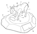
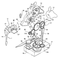
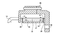
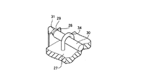
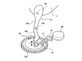
図1は、本発明に係る動作玩具の第1の実施形態を示した外観図、図2は、その動作玩具の駆動部を示した概念的な分解斜視図、図3は、図2におけるIII−III線断面図、図4は、図3における矢視Aの部分斜視図、図5は、図1における矢視Bの脚の駆動機構を示した斜視図である。
(First embodiment)
1. 1 is an external view showing a first embodiment of an action toy according to the present invention, FIG. 2 is a conceptual exploded perspective view showing a drive unit of the action toy, and FIG. 2 is a cross-sectional view taken along line III-III in FIG. 2, FIG. 4 is a partial perspective view taken along arrow A in FIG. 3, and FIG. 5 is a perspective view showing a drive mechanism for the leg shown in FIG.

2.概略説明
第1の実施形態の動作玩具10は、ベース15の上に形象物主体100が設置された構成となっている。
このうち形象物主体100はウマ模型となっていて、その外郭はプラスチックによって形成されている。そして、形象物主体100は、胴11に対して首12が上下に揺動可能に構成され、また、首12に対して頭13が上下に揺動可能に構成されている。さらに、この形象物主体100は、胴11に対して尻尾14が左右に揺動可能に構成され、また、胴11に対して左前脚17aが前後に揺動可能に構成されている。そして、首12、頭13、尻尾14及び左前脚17aは、ベース15内に設置されたソーラモータ16によって駆動されるようになっている。
2. Outline Description The action toy 10 of the first embodiment has a configuration in which a figure main body 100 is installed on a base 15.
Of these, the figure main body 100 is a horse model, and its outline is made of plastic. The figure main body 100 is configured such that the neck 12 can swing up and down with respect to the body 11, and the head 13 can swing up and down with respect to the neck 12. Further, the figure main body 100 is configured such that the tail 14 can swing left and right with respect to the body 11, and the left front leg 17 a can swing back and forth with respect to the body 11. The neck 12, the head 13, the tail 14, and the left front leg 17 a are driven by a solar motor 16 installed in the base 15.

3.キャラクタ及び内部構造
(1)首12及び頭13
首12の外郭と一体的に動作する揺動体12aには金属製の軸19が付設されている。この軸19は揺動体12aの左右両側に延び、胴11の内面に固定された金属製の軸受板20に支持されている。そして、首12は、軸19を中心に上下に揺動可能に構成されている。
ここで、軸19の支持構造について説明すれば、軸19の一方の端部(例えば左側端部)は一方の軸受板20の丸孔に挿入されることによって支持されている。また、軸19の他方の端部(例えば右側端部)の外周には周方向に延在する括れ部つまり環状溝(図示せず)が形成されている。そして、この軸19の他方の端部は他方の軸受板20の丸孔に挿入されることによって支持されている。このとき、環状溝の部分は軸受板20で下方から支持されている。これによって、軸19の軸受板20に対する左右方向の相対移動が防止される。
なお、この実施形態では、丸孔によって軸19を支持したが、円弧状切欠き又はV字状切欠きによって支持してもよい。要は、軸受板28が環状溝31に臨入され、軸19が環状溝の部分にて下方から支持されることである。
3. Character and internal structure (1) Neck 12 and head 13
A metal shaft 19 is attached to the rocking body 12 a that operates integrally with the outer shell of the neck 12. The shaft 19 extends to the left and right sides of the rocking body 12a and is supported by a metal bearing plate 20 fixed to the inner surface of the body 11. The neck 12 is configured to swing up and down around a shaft 19.
Here, the support structure of the shaft 19 will be described. One end portion (for example, the left end portion) of the shaft 19 is supported by being inserted into a round hole of one bearing plate 20. Further, a constricted portion extending in the circumferential direction, that is, an annular groove (not shown) is formed on the outer periphery of the other end portion (for example, the right end portion) of the shaft 19. The other end of the shaft 19 is supported by being inserted into the round hole of the other bearing plate 20. At this time, the portion of the annular groove is supported by the bearing plate 20 from below. Thereby, the relative movement of the shaft 19 in the left-right direction with respect to the bearing plate 20 is prevented.
In this embodiment, the shaft 19 is supported by a round hole. However, the shaft 19 may be supported by an arc-shaped notch or a V-shaped notch. The point is that the bearing plate 28 enters the annular groove 31 and the shaft 19 is supported from below by the annular groove portion.

また、揺動体12aには、上記軸19の近くに、ピン25が付設されている。そして、このピン25には、リンク26の一端部が連結されている。そして、このリンク26に入力がされると、首12が軸19を中心に上下に揺動するようになっている。このリンク26はプラスチックによって形成され、過度の負荷が加わると弾性変形可能となるように屈曲した形状となっている。これによって、首12の揺動中に、人が首12を強制停止させた場合に、内部機構等が破壊されるのが防止される。   Further, a pin 25 is attached to the rocking body 12 a near the shaft 19. The pin 25 is connected to one end of a link 26. When the link 26 is input, the neck 12 swings up and down about the shaft 19. The link 26 is made of plastic and has a bent shape so as to be elastically deformable when an excessive load is applied. This prevents the internal mechanism and the like from being destroyed when a person forcibly stops the neck 12 while the neck 12 is swinging.

揺動体12aの頭部側端部には頭13が上下に揺動可能に取り付けられている。
すなわち、頭13は左半部と右半部の2つのパーツから構成されている。一方、揺動体12aの先端側端部には軸21が付設されている。この軸21は揺動体12aを貫通して左右に突出している。そして、軸21のうちで揺動体12aの左方に突出した軸部分に頭13の左半部が上下に揺動可能に取り付けられ、一方、軸21のうちで揺動体12aの右側に突出した軸部分に頭13の右半部が上下に揺動可能に取り付けられるようになっている。
また、頭13の左半部の内面には、軸21に対して軸芯をずらした位置に、ピン22aが付設されている。一方、揺動体12aには、上記軸21の軸芯を曲率中心とする弧状孔12bが形成されている。そして、頭13の左半部は、ピン22aが弧状孔12bに挿入された状態で、軸21に取り付けられる。
また、頭13の右半部の内面には、軸21に対して軸芯をずらした位置で且つ上記ピン22aの付設位置とは重ならない位置に、ピン22cが付設されている。このピン22cにはリンク23の頭部側端部が係合している。
なお、頭13の左半部及び右半部は、揺動体12aに対する上下の揺動を妨げとならない位置に設けられたピン(図示せず)とピン穴(図示せず)とを嵌合させることによって、相互に組み付けられるようになっている。勿論、頭13の左半部及び右半部は螺着によって相互に組み付けられるものであってもよい。、
A head 13 is attached to the head side end of the rocking body 12a so as to be rockable up and down.
That is, the head 13 is composed of two parts, a left half part and a right half part. On the other hand, a shaft 21 is attached to the end of the swinging body 12a. The shaft 21 penetrates the rocking body 12a and protrudes left and right. The left half of the head 13 is attached to the shaft portion of the shaft 21 that protrudes to the left of the oscillating body 12a so as to be able to oscillate up and down, while the shaft 21 protrudes to the right of the oscillating body 12a. The right half of the head 13 is attached to the shaft portion so as to be swingable up and down.
In addition, a pin 22 a is attached to the inner surface of the left half of the head 13 at a position where the axis is shifted with respect to the shaft 21. On the other hand, the oscillating body 12a is formed with an arc-shaped hole 12b whose center of curvature is the axis of the shaft 21. The left half of the head 13 is attached to the shaft 21 with the pin 22a inserted into the arcuate hole 12b.
Further, a pin 22c is attached to the inner surface of the right half of the head 13 at a position where the axis is shifted with respect to the shaft 21 and does not overlap with the attachment position of the pin 22a. The head side end of the link 23 is engaged with the pin 22c.
In addition, the left half part and the right half part of the head 13 are fitted with a pin (not shown) and a pin hole (not shown) provided at positions that do not hinder vertical swinging with respect to the swinging body 12a. As a result, they can be assembled together. Of course, the left half and the right half of the head 13 may be assembled together by screwing. ,

上記リンク23は上記ピン22bから上記軸19にまで亘って延在する長さ寸法を有している。リンク23には、頭部側端部に二股状係合部23aが形成され、胴部側端部に弧状係合部23bが形成されている。
そして、このリンク23は、中間位置に付設した軸12cを介して、揺動体12aに支持され、軸12cを中心に揺動可能となっている。その際、上記二股状係合部23aの股間と上記ピン22bとが係合状態とされ、上記弧状係合部23bは上記軸19の上に乗った状態とされる。
また、リンク23には、弧状湾曲部の近くに、突起24が付設されている。そして、リンク23は、突起24から入力がなされると、軸12cを中心に揺動する。その結果、頭13が首12に対して上下に揺動することとなる。
The link 23 has a length dimension extending from the pin 22 b to the shaft 19. The link 23 is formed with a bifurcated engagement portion 23a at the head side end and an arcuate engagement portion 23b at the trunk side end.
The link 23 is supported by the swinging body 12a via a shaft 12c attached to an intermediate position, and can swing about the shaft 12c. At that time, the crotch of the bifurcated engagement portion 23a and the pin 22b are engaged, and the arcuate engagement portion 23b is put on the shaft 19.
Further, the link 23 is provided with a protrusion 24 near the arcuate curved portion. The link 23 swings about the shaft 12c when input is made from the protrusion 24. As a result, the head 13 swings up and down with respect to the neck 12.

揺動体12aの胴部側端部にはウエイトW1が設けられている。このウエイトW1は、軸19を中心として揺動する首12及び頭13において、重力に基づく一方向のトルクと他方向のトルクとのバランスを調整するためのものであり、この調整によって、起動時及び揺動時のトルクを減少させることとしている。   A weight W1 is provided at the end of the oscillating body 12a on the trunk side. This weight W1 is for adjusting the balance between the torque in one direction based on gravity and the torque in the other direction on the neck 12 and the head 13 that swing around the shaft 19, and this adjustment makes it possible to The torque at the time of swinging is reduced.

(2)脚17
形象物主体100は、4つの脚17のうち左前脚17aだけが動作可能に構成されている。すなわち、左前脚17aは、図5に示すように、上部脚18a及び下部脚18bの2つのパーツから構成されている。そして、上部脚18aは軸18cを中心に揺動可能に構成されている。また、下部脚18bは軸18dを中心に揺動可能に構成されている。そして、形象物主体100は、下部脚18bが上方に突き上げられたときに、膝上げ動作を行うように構成されている。
(2) Leg 17
The figurative main body 100 is configured such that only the left front leg 17 a among the four legs 17 can be operated. That is, as shown in FIG. 5, the left front leg 17a is composed of two parts, an upper leg 18a and a lower leg 18b. The upper leg 18a is configured to be swingable about a shaft 18c. The lower leg 18b is configured to be swingable about a shaft 18d. The figurative main body 100 is configured to perform a knee lifting operation when the lower leg 18b is pushed upward.

(3)尻尾14
尻尾(揺動体)14は、図2に示すように、支持板27に支持されている。支持板27は、その主面が水平状態となるように胴11に設けられる。具体的には、胴11は左右2つのパーツから構成される。そこで、左右2つのパーツの内面にそれぞれ差込みを形成しておき、その差込みに支持板27を差し込むことによって、支持板27は胴11に固定される。
支持板27の上面の前後位置には、図3に示すように、金属製の軸受板28が付設されている。軸受板28には、図4に示すように、上方に開口する円弧状切欠き29が形成されている。
一方、尻尾14の付け根部分には軸30が付設されている。軸30の外周には、軸受板28に対応する部分に周方向に延在する括れ部つまり環状溝31が形成されている。
そして、軸受板28が環状溝31に臨入され、軸30は環状溝31の部分にて下方から支持されている。
なお、この実施形態では、円弧状切欠き29としたが、丸孔やV字状切欠きであってもよい。要は、軸受板28が環状溝31に臨入され、軸30が環状溝31の部分にて下方から支持されることである。
また、支持板27には、逆U字状の枠34が付設されている。そして、尻尾14の軸30が支持板27から離脱するのを防止している。
(3) Tail 14
The tail (oscillator) 14 is supported by a support plate 27 as shown in FIG. The support plate 27 is provided on the trunk 11 so that its main surface is in a horizontal state. Specifically, the trunk | drum 11 is comprised from two parts on either side. Therefore, the support plate 27 is fixed to the body 11 by forming inserts on the inner surfaces of the two left and right parts and inserting the support plate 27 into the inserts.
As shown in FIG. 3, a metal bearing plate 28 is attached to the front and rear positions of the upper surface of the support plate 27. As shown in FIG. 4, the bearing plate 28 is formed with an arc-shaped notch 29 that opens upward.
On the other hand, a shaft 30 is attached to the base portion of the tail 14. On the outer periphery of the shaft 30, a constricted portion extending in the circumferential direction, that is, an annular groove 31 is formed in a portion corresponding to the bearing plate 28.
The bearing plate 28 enters the annular groove 31, and the shaft 30 is supported by the annular groove 31 from below.
In this embodiment, the arc-shaped notch 29 is used, but it may be a round hole or a V-shaped notch. The point is that the bearing plate 28 enters the annular groove 31 and the shaft 30 is supported by the annular groove 31 from below.
The support plate 27 is provided with an inverted U-shaped frame 34. The shaft 30 of the tail 14 is prevented from being detached from the support plate 27.

また、尻尾14には、ウエイトW2及びW5が付設されている。このウエイトW2及びW5は、尻尾14の重量によって、軸30における尻尾14とは反対側部分が浮いてしまい軸受板34から離れてしまうのを防止する働きをする。また、このウエイトW2及びW5は、軸30を中心として揺動する尻尾14において、重力に基づく一方向のトルクと他方向のトルクとのバランスをも調整している。この調整によって、起動時及び揺動時のトルクを減少させることとしている。なお、特に、軸30の上方に設けられるウエイトW5は尻尾14の揺動速度の調整用のウエイトである。
さらに、ウエイトW2の付設部分近くには水平方向に延在する舌片33が付設されている。そして、尻尾14は、舌片33から入力がなされると、軸30を中心に揺動する。その結果、尻尾14が胴11に対して左右に揺動することとなる。
Further, weights W2 and W5 are attached to the tail 14. The weights W2 and W5 function to prevent the portion of the shaft 30 opposite to the tail 14 from floating due to the weight of the tail 14 and separating from the bearing plate 34. The weights W2 and W5 also adjust the balance between the torque in one direction based on gravity and the torque in the other direction at the tail 14 that swings about the shaft 30. By this adjustment, the torque at the time of starting and swinging is reduced. In particular, a weight W5 provided above the shaft 30 is a weight for adjusting the swing speed of the tail 14.
Further, a tongue piece 33 extending in the horizontal direction is provided near the attachment portion of the weight W2. When the input is made from the tongue piece 33, the tail 14 swings around the shaft 30. As a result, the tail 14 swings left and right with respect to the trunk 11.

4.ベース15及び内部構造
ベース15の表面にはソーラバッテリ64が付設されている。また、ベース64の内部には、制御回路54、ソーラモータ16及び歯車列53とがケース51に収納された状態で設けられている。
制御回路54は、ソーラモータ16の電磁コイルに流す電流を制御するためのものである。また、ソーラモータ16は、永久磁石が付設されたロータ16aと、ロータ16aに対峙して設けられた電磁コイル(図示せず)とを備えており、電磁コイルに流した電流によってロータ16aを回転させるように構成されている。歯車列53は、ソーラモータ16のロータによって駆動されるようになっている。この歯車列53は動力伝達機構の一部を構成する。なお、ソーラモータ16にあっては、ロータ16a側に電磁コイルを設け、ステータ側に永久磁石を設けてもよい。
4). Base 15 and Internal Structure A solar battery 64 is attached to the surface of the base 15. Further, the control circuit 54, the solar motor 16, and the gear train 53 are provided in the case 51 inside the base 64.
The control circuit 54 is for controlling the current flowing through the electromagnetic coil of the solar motor 16. Further, the solar motor 16 includes a rotor 16a provided with a permanent magnet and an electromagnetic coil (not shown) provided to face the rotor 16a, and rotates the rotor 16a by a current passed through the electromagnetic coil. It is configured as follows. The gear train 53 is driven by the rotor of the solar motor 16. The gear train 53 constitutes a part of the power transmission mechanism. In the solar motor 16, an electromagnetic coil may be provided on the rotor 16a side and a permanent magnet may be provided on the stator side.

5.動力伝達機構
動力伝達機構の一部を構成する歯車列53は、互いに平行で鉛直方向に延在する軸を持つ複数の歯車から構成されている。
5). Power Transmission Mechanism The gear train 53 that constitutes a part of the power transmission mechanism is composed of a plurality of gears having shafts that are parallel to each other and extend in the vertical direction.

歯車列53を構成する1つの歯車53aの端面はケース51の表面から露出している。この歯車53aの端面には、図2及び図5に示すように、当該歯車53aの軸芯からずれた位置に2つの突起(カム)55が付設されている。
一方、歯車53aの上方には、軸39を中心に揺動する揺動体37が設けられている。この揺動体37は軸39の両側にまで延在している。
揺動体37の一端部は2股状に分岐しており、一方の分岐部の先端にはピン38が付設されている。そして、ピン38は、左前脚17aの下側に延設した舌片35の丸孔36に挿入されている。他方の分岐部の先端には三角状突起41が付設されている。この三角状突起41は、歯車53aが回転した際、突起55が突き当たる位置に配設される。
揺動体37の他端部にはウエイトW3が設けられる。このウエイトW3は、軸39を中心として揺動する揺動体37において、重力に基づく一方向のトルクと他方向のトルクとのバランスを調整するためのものであり、この調整によって、起動時及び揺動時のトルクを減少させることとしている。
The end face of one gear 53 a constituting the gear train 53 is exposed from the surface of the case 51. As shown in FIGS. 2 and 5, two projections (cams) 55 are attached to the end face of the gear 53a at positions shifted from the axis of the gear 53a.
On the other hand, an oscillating body 37 that oscillates about a shaft 39 is provided above the gear 53a. The rocking body 37 extends to both sides of the shaft 39.
One end of the oscillating body 37 is bifurcated, and a pin 38 is attached to the tip of one branch. And the pin 38 is inserted in the round hole 36 of the tongue piece 35 extended under the left front leg 17a. A triangular protrusion 41 is attached to the tip of the other branch portion. The triangular protrusion 41 is disposed at a position where the protrusion 55 abuts when the gear 53a rotates.
A weight W <b> 3 is provided at the other end of the rocking body 37. This weight W3 is for adjusting the balance between the torque in one direction based on gravity and the torque in the other direction in the swinging body 37 that swings about the shaft 39. The torque during operation is reduced.

また、歯車53を構成し上記歯車53aに噛合する歯車53bの端面もケース51の表面から露出している。この歯車53bの端面には、図示しないが、当該歯車53bの軸芯近くに、凹凸からなる連結部が付設されている。
一方、歯車53bの上方には、形象物主体100の右前脚17bが位置している。この右前脚17b内には、鉛直方向に延在する軸58が挿通されている。そして、軸58の下端部はベース15内に臨んでおり、軸下端には、上記歯車53bの連結部と上方から係合して軸連結する凹凸からなる連結部56が付設されている。これら軸58、連結部56も動力伝達機構の一部を構成する。
Further, the end surface of the gear 53 b that constitutes the gear 53 and meshes with the gear 53 a is also exposed from the surface of the case 51. Although not shown, an end portion of the gear 53b is provided with a connecting portion made of unevenness near the axis of the gear 53b.
On the other hand, the right front leg 17b of the figure main body 100 is located above the gear 53b. A shaft 58 extending in the vertical direction is inserted into the right front leg 17b. A lower end portion of the shaft 58 faces the base 15, and a connecting portion 56 is provided at the lower end of the shaft. The connecting portion 56 is an uneven portion that engages and connects the connecting portion of the gear 53 b from above. The shaft 58 and the connecting portion 56 also constitute a part of the power transmission mechanism.

軸58の上端部は胴11内に臨んでおり、軸上端には歯車59が付設されている。この歯車59には、胴11に設置される歯車列57が連結されている。この歯車列57は、上記軸58に直交する軸に付設され上記歯車59に噛合する歯車57aと、歯車57aと同軸に付設され歯車57aと一体的に回転する歯車57bと、歯車57aの軸に平行な軸に付設され歯車57bに噛合する歯車57cと、歯車57cの軸に平行な軸に付設され歯車57cに噛合する歯車57dと、歯車57dの軸に平行な軸に付設され歯車57cに噛合する歯車57eとから構成されている。これら歯車59及び歯車列57も動力伝達機構の一部を構成する。このように歯車の軸を互いに平行した歯車列で動力伝達を行うことによって、伝達ロスを極力軽減させることができる。つまり、歯車の軸を互いに直交させて動力を伝達すると、その分、動力伝達ロスが生じる。したがって、ここでは、歯車の軸を互いに平行した歯車列で動力伝達を行うようにし、その歯車列を構成する歯車の回転動力によって後述のカム、揺動体等を動作させるようにしている。   An upper end portion of the shaft 58 faces the body 11, and a gear 59 is attached to the upper end of the shaft. A gear train 57 installed on the body 11 is connected to the gear 59. The gear train 57 is attached to a shaft orthogonal to the shaft 58 and meshes with the gear 59, a gear 57b coaxially attached to the gear 57a and rotated integrally with the gear 57a, and a shaft of the gear 57a. A gear 57c attached to the parallel shaft and meshed with the gear 57b; a gear 57d attached to the shaft parallel to the shaft of the gear 57c and meshed with the gear 57c; And a gear 57e. The gear 59 and the gear train 57 also constitute a part of the power transmission mechanism. In this way, transmission loss can be reduced as much as possible by performing power transmission with a gear train in which gear shafts are parallel to each other. That is, if power is transmitted with the gear shafts orthogonal to each other, a power transmission loss is generated accordingly. Therefore, here, power is transmitted by a gear train whose gear shafts are parallel to each other, and a cam, a swinging body, etc., which will be described later, are operated by the rotational power of the gears constituting the gear train.

ここで、歯車57bの端面には、外周面が波形状で首12が下がったときだけ上記突起24と当接可能なカム61が付設されている。このカム61は、歯車57bの回転によって、首12が下がったときだけ、上記突起24と接触し、頭13を上下動させる。このカム61の形状を変えることによって、頭13の動作タイミングを様々に調整できる。例えば、ウマが干し草を食べているような微妙な動作を実現できる。
歯車57cの端面には、当該歯車57cの軸芯からずれた位置に偏心ピン62が付設されている。この偏心ピン62は、上記リンク26の他端部が互いに回り対偶をなすように連結されている。したがって、歯車57bの回転によって、リンク26を介して、首12が上下に揺動することになる。
歯車57dは遊び歯車である。
歯車57eの端面には、当該歯車57eの軸芯からずれた位置に偏心ピン63が付設されている。この偏心ピン63は、歯車57eの回転によって、上記舌片33を叩き、尻尾14を左右に揺動させる。
Here, an end face of the gear 57b is provided with a cam 61 that can come into contact with the protrusion 24 only when the outer peripheral surface is corrugated and the neck 12 is lowered. The cam 61 comes into contact with the protrusion 24 and moves the head 13 up and down only when the neck 12 is lowered by the rotation of the gear 57b. By changing the shape of the cam 61, the operation timing of the head 13 can be variously adjusted. For example, a subtle movement can be realized as if a horse is eating hay.
An eccentric pin 62 is attached to the end face of the gear 57c at a position shifted from the axis of the gear 57c. The eccentric pin 62 is connected so that the other end portions of the link 26 turn around each other to form a pair. Therefore, the neck 12 swings up and down via the link 26 by the rotation of the gear 57b.
The gear 57d is an idle gear.
An eccentric pin 63 is attached to the end face of the gear 57e at a position shifted from the axis of the gear 57e. The eccentric pin 63 hits the tongue 33 and rotates the tail 14 left and right by the rotation of the gear 57e.

(第2の実施形態)
1.使用する図の説明
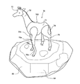
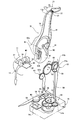
図6および図7は、本発明に係る動作玩具の第2の実施形態を示している。図6は、本発明に係る動作玩具の第2の実施形態を示した外観図、図7は、その動作玩具の駆動部を示した概念的な分解斜視図である。
(Second Embodiment)
1. Description of Figures Used FIG. 6 and FIG. 7 show a second embodiment of the moving toy according to the present invention. FIG. 6 is an external view showing a second embodiment of the action toy according to the present invention, and FIG. 7 is a conceptual exploded perspective view showing a drive unit of the action toy.

2.概略と第1の実施形態との共通点
この動作玩具70の形象物主体700はキリン模型であって、その外郭はプラスチックによって形成されている。そして、形象物主体700は、胴71に対して首72が上下に揺動可能に構成され、また、首72に対して頭73が上下に揺動可能に構成されている。さらに、この形象物主体700は、胴71に対して尻尾74が左右に揺動可能に構成され、また、胴71に対して左前脚75aが前後に揺動可能に構成されている。そして、首72、頭73、尻尾74及び左前脚75aは、ベース75内に設置されたソーラモータ16によって駆動されるようになっている。この点で、第2の実施形態の動作玩具70は第1の実施形態の動作玩具10と共通する。
また、第2の実施形態の動作玩具70は、その他の点でも第1の実施形態と相当な部分で共通する。特に、ベース86内の構成は、第1の実施形態のベース15内の構成と同一である。したがって、第2の実施形態の動作玩具70が第1の実施形態の動作玩具10と共通又は一致する部分は、図1から図5で使用した符号と同一符号を図6及び図7に付し、その説明を適宜省略する。
2. Outline and common points of the first embodiment The figure main body 700 of the moving toy 70 is a giraffe model, and its outline is made of plastic. The main body 700 is configured such that the neck 72 can swing up and down with respect to the body 71, and the head 73 can swing up and down with respect to the neck 72. Further, the figure main body 700 is configured such that the tail 74 can swing left and right with respect to the body 71, and the left front leg 75 a can swing back and forth with respect to the body 71. The neck 72, the head 73, the tail 74, and the left front leg 75a are driven by the solar motor 16 installed in the base 75. In this respect, the motion toy 70 of the second embodiment is common to the motion toy 10 of the first embodiment.
In addition, the operation toy 70 of the second embodiment is common to the first embodiment in other respects. In particular, the configuration in the base 86 is the same as the configuration in the base 15 of the first embodiment. Accordingly, the same reference numerals as those used in FIGS. 1 to 5 are attached to the portions in FIG. 6 and FIG. 7 that are the same as or similar to those of the moving toy 10 of the first embodiment. The description will be omitted as appropriate.

3.相違点
第2の実施形態の動作玩具70は次の点で第1の実施形態の動作玩具10とは相違している。
第1に、首72及び頭73の動作機構が両者で異なり、第2に、第2の実施形態の形象物主体700に設けられる歯車列57には遊び歯車(図2に符号57dで示す歯車)が存在していない点である。
3. Difference The moving toy 70 of the second embodiment is different from the moving toy 10 of the first embodiment in the following points.
First, the operating mechanisms of the neck 72 and the head 73 are different from each other. Second, the gear train 57 provided in the main body 700 of the second embodiment has an idle gear (a gear indicated by 57d in FIG. 2). ) Does not exist.

4.相違点の説明
首72と一体的に動作する揺動体12aには、首72を上下に揺動可能に支持する軸19の近くにピン82aが付設されている。ピン82aには、長孔82bが形成されたレバー82が固定して取り付けられている。レバー82の長孔82bには、歯車57cの端面に付設された偏心ピン62が挿入されている。そして、首72は、歯車57cが回転することによって、胴71に対して一時的に上下に動作するように構成されている。
4). Explanation of Differences The swinging body 12a that operates integrally with the neck 72 is provided with a pin 82a near the shaft 19 that supports the neck 72 so as to swing up and down. A lever 82 having a long hole 82b is fixedly attached to the pin 82a. An eccentric pin 62 attached to the end face of the gear 57c is inserted into the elongated hole 82b of the lever 82. The neck 72 is configured to temporarily move up and down with respect to the body 71 as the gear 57c rotates.

また、軸19には、L字状のレバー80が屈曲部を中心に揺動可能となるように取り付けられている。このレバー80の一端部にはロッド(又はワイヤ)81の一端が連結されている。また、ロッド81の他端は、頭72の内面のピン22に連結されている。そして、頭73は、歯車57bが回転することによって、ロッド81が一時的に押し上げられ、これによって、首72に対して上下に揺動するように構成されている。   Further, an L-shaped lever 80 is attached to the shaft 19 so as to be able to swing around the bent portion. One end of a rod (or wire) 81 is connected to one end of the lever 80. The other end of the rod 81 is connected to the pin 22 on the inner surface of the head 72. The head 73 is configured to swing up and down with respect to the neck 72 by temporarily pushing up the rod 81 as the gear 57 b rotates.

(第3の実施形態)
1.使用する図の説明
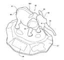
図8および図9は、本発明に係る動作玩具の第3の実施形態を示している。、図8は、本発明に係る動作玩具の第3の実施形態を示した外観図、図9は、その動作玩具の駆動部を示した概念的な分解斜視図である。
(Third embodiment)
1. Description of Figures Used FIG. 8 and FIG. 9 show a third embodiment of the moving toy according to the present invention. FIG. 8 is an external view showing a third embodiment of the action toy according to the present invention, and FIG. 9 is a conceptual exploded perspective view showing a drive unit of the action toy.

2.概略と第1の実施形態との共通点
この動作玩具90の形象物主体900はゾウ模型であって、その外郭はプラスチックによって形成されている。そして、形象物主体900は、胴91に対して頭92が左右に揺動可能に構成され、また、頭92に対して鼻93が上下に揺動可能に構成され、さらに、頭92に対して耳98が前後に揺動可能に構成されている。さらに、この形象物主体900は、胴91に対して尻尾94が左右に揺動可能に構成されている。そして、頭92、鼻93、耳98及び尻尾94は、ベース107内に設置されたソーラモータ16によって駆動されるようになっている。
この第3の実施形態の動作玩具90は、第1の実施形態と相当な部分で共通する。特に、ベース107内の構成は、第1の実施形態のベース15内の構成と同一である。したがって、第3の実施形態の動作玩具90が第1の実施形態の動作玩具10と共通又は一致する部分は、図1から図5で使用した符号と同一符号を図8及び図9に付し、その説明を適宜省略する。
2. Outline and common points of the first embodiment The figure main body 900 of the moving toy 90 is an elephant model, and its outline is made of plastic. The figure main body 900 is configured such that the head 92 can swing left and right with respect to the torso 91, and the nose 93 can swing up and down with respect to the head 92. The ear 98 is configured to be swingable back and forth. Further, the figure main body 900 is configured such that a tail 94 can swing left and right with respect to the trunk 91. The head 92, nose 93, ear 98 and tail 94 are driven by the solar motor 16 installed in the base 107.
The action toy 90 of the third embodiment is common to the first embodiment in a considerable part. In particular, the configuration in the base 107 is the same as the configuration in the base 15 of the first embodiment. Therefore, the same reference numerals as those used in FIGS. 1 to 5 are attached to the parts that are the same as or identical to the action toy 10 of the first embodiment in FIGS. The description will be omitted as appropriate.

3.相違点
(1)頭92
この動作玩具90では、図9に示すように、平面視でコ字状を成す揺動板95が、頭92に設けられている。この揺動板95は、鉛直方向に延在する軸96を中心に揺動可能に胴91に支持されている。この揺動板95は支持部材(図示せず)を介して頭92に取り付けられている。
また、揺動板95には、長孔101aが形成されたリンク101の一端が軸95から偏心した位置に連結されている。
したがって、頭92は、リンク101が動作した際に、揺動板95が軸96を中心に上記支持部材(図示せず)に対して揺動した際に、一体的に左右方向に揺動する。
なお、リンク101は、プラスチックによって形成され、過度の負荷が加わると弾性変形可能となるように屈曲した形状となっている。これによって、頭92の揺動中に頭92を強制停止させた場合に、内部機構等が破壊されるのが防止される。
3. Difference (1) Head 92
In the moving toy 90, as shown in FIG. 9, a swing plate 95 having a U-shape in plan view is provided on the head 92. The swing plate 95 is supported by the body 91 so as to be swingable about a shaft 96 extending in the vertical direction. The swing plate 95 is attached to the head 92 via a support member (not shown).
Further, one end of the link 101 in which the long hole 101 a is formed is connected to the swing plate 95 at a position eccentric from the shaft 95.
Accordingly, when the link 101 is operated, the head 92 integrally swings in the left-right direction when the swing plate 95 swings with respect to the support member (not shown) around the shaft 96. .
The link 101 is made of plastic and has a bent shape so as to be elastically deformable when an excessive load is applied. This prevents the internal mechanism and the like from being destroyed when the head 92 is forcibly stopped while the head 92 is swinging.

(2)耳98
また、この揺動板95の両側部には、鉛直方向に延在する軸97を中心に耳98が揺動可能に支持されている。したがって、耳98は、軸97を中心にして、頭92に対して左右方向に揺動可能となっている。一方の軸97には、右耳と一体的に動作するリンク102の一端が連結されている。また、他方の軸97には、長孔104aが形成され左耳と一体的に動作するリンク104の一端が連結されている。そして、リンク104の長孔104aには、リンク102の他端に付設したピン103が挿入されている。そして、ピン103には剛性の高いワイヤ(又はロッド)121の一端が連結されている。柔軟なワイヤでもよいが、その場合にはばね等の復帰手段が必要となる。
したがって、耳98は、ワイヤ121が駆動された際に、リンク102及び103が軸97を中心に揺動することで、頭92に対して前後に揺動する。
なお、ピン103の動作案内をするガイド孔を設けてもよい。これによって、左右の耳98の動作に変化を持たせることができる。
(2) Ear 98
Further, on both sides of the swing plate 95, ears 98 are swingably supported around a shaft 97 extending in the vertical direction. Therefore, the ear 98 can swing in the left-right direction with respect to the head 92 about the shaft 97. One shaft 97 is connected to one end of a link 102 that operates integrally with the right ear. The other shaft 97 is connected to one end of a link 104 which is formed with a long hole 104a and operates integrally with the left ear. A pin 103 attached to the other end of the link 102 is inserted into the long hole 104 a of the link 104. The pin 103 is connected to one end of a highly rigid wire (or rod) 121. A flexible wire may be used, but in that case, a return means such as a spring is required.
Therefore, the ear 98 swings back and forth with respect to the head 92 by the links 102 and 103 swinging about the shaft 97 when the wire 121 is driven.
A guide hole for guiding the operation of the pin 103 may be provided. Thereby, a change can be given to the operation of the left and right ears 98.

(3)鼻92
また、頭92の基端には金属製の軸99が付設されている。この軸99は鼻(揺動体)92の左右両側に延び、頭92の内面に固定された金属製の軸受板100に支持されている。そして、鼻92は、軸99を中心に上下に揺動可能に構成されている。
ここで、軸99の支持構造について説明すれば、軸99の一方の端部(例えば左側端部)は一方の軸受板100の丸孔に挿入されることによって支持されている。また、軸99の他方の端部(例えば右側端部)の外周には周方向に延在する括れ部つまり環状溝が形成されている。そして、この軸99の他方の端部は他方の軸受板100の丸孔に挿入されることによって支持されている。このとき、環状溝の部分は軸受板100で下方から支持されている。これによって、軸99の軸受板100に対する左右方向の相対移動が防止される。
また、鼻93の基端部は、後方に延設され、その延設部にウエイトW4が配設されている。このウエイトW4は、軸99を中心として揺動する鼻92において、重力に基づく一方向のトルクと他方向のトルクとのバランスを調整するためのものであり、この調整によって、起動時及び揺動時のトルクを減少させることとしている。
さらに、鼻93の軸99から偏心した部分にはワイヤ120の一端が連結されている。したがって、鼻93は、ワイヤ120が駆動された際に、頭92に対して上下に揺動する。
(3) Nose 92
A metal shaft 99 is attached to the base end of the head 92. The shaft 99 extends to the left and right sides of the nose (oscillator) 92 and is supported by a metal bearing plate 100 fixed to the inner surface of the head 92. The nose 92 is configured to be swingable up and down around the shaft 99.
Here, the support structure of the shaft 99 will be described. One end portion (for example, the left end portion) of the shaft 99 is supported by being inserted into a round hole of one bearing plate 100. Further, a constricted portion extending in the circumferential direction, that is, an annular groove is formed on the outer periphery of the other end portion (for example, the right end portion) of the shaft 99. The other end of the shaft 99 is supported by being inserted into the round hole of the other bearing plate 100. At this time, the annular groove portion is supported by the bearing plate 100 from below. Thereby, the relative movement of the shaft 99 with respect to the bearing plate 100 in the left-right direction is prevented.
Moreover, the base end part of the nose 93 is extended rearward, and the weight W4 is arrange | positioned by the extension part. The weight W4 is used to adjust the balance between the torque in one direction based on gravity and the torque in the other direction in the nose 92 that swings around the shaft 99. The torque at the time is to be reduced.
Further, one end of the wire 120 is connected to a portion eccentric from the shaft 99 of the nose 93. Therefore, the nose 93 swings up and down with respect to the head 92 when the wire 120 is driven.

(4)尻尾94
胴91の尻尾94の支持構造は、上記第1の実施形態と同様なので、同一の符号を付して、説明を省略する。但し、この実施形態では、ウエイトW2に、後方に延びる舌片106が形成されている。
(4) Tail 94
Since the support structure of the tail 94 of the trunk 91 is the same as that of the first embodiment, the same reference numerals are given and description thereof is omitted. However, in this embodiment, a tongue piece 106 extending rearward is formed on the weight W2.

(5)動力伝達機構108
軸58の上端部は胴91内に臨んでおり、軸上端には歯車59が付設されている。この歯車59には、胴11に設置される歯車列109が連結されている。この歯車列109は、上記軸58に平行な軸に付設され上記歯車59に噛合する歯車109aと、軸58に平行な軸に付設され歯車109aに噛合する歯車109bと、軸58に平行な軸に付設され歯車109bに噛合する歯車109cと、軸58に平行な軸に付設され歯車109cに噛合する歯車109dとから構成されている。このように歯車の軸を互いに平行した歯車列で動力伝達を行うことによって、伝達ロスを極力軽減させることができる。つまり、歯車の軸を互いに直交させて動力を伝達すると、その分、動力伝達ロスが生じる。したがって、ここでは、歯車の軸を互いに平行した歯車列で動力伝達を行うようにし、その歯車列を構成する歯車の回転動力によって後述のカム、揺動体等を動作させるようにしている。
(5) Power transmission mechanism 108
The upper end portion of the shaft 58 faces the body 91, and a gear 59 is attached to the upper end of the shaft. A gear train 109 installed on the trunk 11 is connected to the gear 59. The gear train 109 includes a gear 109 a attached to an axis parallel to the shaft 58 and meshed with the gear 59, a gear 109 b attached to an axis parallel to the shaft 58 and meshed with the gear 109 a, and an axis parallel to the shaft 58. The gear 109c is engaged with the gear 109b and the gear 109d is engaged with the gear 109c. In this way, transmission loss can be reduced as much as possible by performing power transmission with a gear train in which gear shafts are parallel to each other. That is, if power is transmitted with the gear shafts orthogonal to each other, a power transmission loss is generated accordingly. Therefore, here, power is transmitted by a gear train whose gear shafts are parallel to each other, and a cam, a swinging body, etc., which will be described later, are operated by the rotational power of the gears constituting the gear train.

ここで、歯車109aは遊び歯車である。
歯車109bの端面には、当該歯車109bの軸芯からずれた位置に偏心ピン110が付設されている。この偏心ピン110は、上記リンク101の長孔101aに挿入されている。そして、歯車109bの回転によって、リンク101を介して、揺動板95を軸96を中心に左右に揺動させる。
歯車109cと同じ軸に付設され当該歯車109cと一体的に回転する回転体112には、当該回転体112の軸芯からずれた位置に偏心ピン113が付設されている。この偏心ピン113には、上記ワイヤ120の他端が連結されている。したがって、歯車109cの回転によって、ワイヤ120を介して、鼻93が上下に揺動することになる。
歯車109dと同じ軸に付設され当該歯車109dと一体的に回転する一の回転体115には、当該回転体115の軸芯からずれた位置に偏心ピン116が付設されている。この偏心ピン116には、上記ワイヤ121の他端が連結されている。したがって、歯車109dの回転によって、ワイヤ121を介して、耳98が前後に揺動することになる。
歯車109dと同じ軸に付設され当該歯車109dと一体的に回転する他の回転体117には、当該回転体117の軸芯からずれた位置に突起118が付設されている。この突起118は、歯車109dの回転によって、上記舌片106を叩き、尻尾14を左右に揺動させる。
Here, the gear 109a is an idle gear.
An eccentric pin 110 is attached to the end face of the gear 109b at a position shifted from the axis of the gear 109b. The eccentric pin 110 is inserted into the long hole 101 a of the link 101. Then, the rotation of the gear 109 b causes the swing plate 95 to swing left and right about the shaft 96 via the link 101.
An eccentric pin 113 is attached to the rotating body 112 attached to the same shaft as the gear 109c and rotating integrally with the gear 109c at a position shifted from the axis of the rotating body 112. The eccentric pin 113 is connected to the other end of the wire 120. Accordingly, the rotation of the gear 109c causes the nose 93 to swing up and down via the wire 120.
One rotating body 115 attached to the same shaft as the gear 109d and rotating integrally with the gear 109d is provided with an eccentric pin 116 at a position shifted from the axis of the rotating body 115. The eccentric pin 116 is connected to the other end of the wire 121. Therefore, the ear 98 swings back and forth through the wire 121 by the rotation of the gear 109d.
On another rotating body 117 attached to the same shaft as the gear 109d and rotating integrally with the gear 109d, a protrusion 118 is attached at a position shifted from the axis of the rotating body 117. The protrusion 118 hits the tongue piece 106 by the rotation of the gear 109d and swings the tail 14 sideways.

本発明に係る動作玩具の第1の実施形態を示した外観図である。It is the external view which showed 1st Embodiment of the operation | movement toy based on this invention. 図1の動作玩具の駆動部を示した概念的な分解斜視図である。FIG. 2 is a conceptual exploded perspective view showing a drive unit of the moving toy in FIG. 1. 図2におけるIII−III線断面図である。It is the III-III sectional view taken on the line in FIG. 図3の一部拡大斜視図である。FIG. 4 is a partially enlarged perspective view of FIG. 3. 図1における脚の駆動機構を示した斜視図である。It is the perspective view which showed the drive mechanism of the leg in FIG. 本発明に係る動作玩具の第2の実施形態を示した外観図である。It is the external view which showed 2nd Embodiment of the operation | movement toy based on this invention. 図6の動作玩具の駆動部を示した概念的な分解斜視図である。FIG. 7 is a conceptual exploded perspective view showing a drive unit of the moving toy in FIG. 6. 本発明に係る動作玩具の第3の実施形態を示した外観図である。It is the external view which showed 3rd Embodiment of the operation | movement toy based on this invention. 図8の動作玩具の駆動部を示した概念的な分解斜視図である。FIG. 9 is a conceptual exploded perspective view showing a drive unit of the moving toy in FIG. 8.

符号の説明Explanation of symbols

10,70,90 動作玩具
12a,37 揺動体
14,74,94 尻尾(揺動体)
15,86,107 ベース
16 ソーラモータ
20,28 軸受板
29,29 切欠き
30 軸
31 環状溝
W1,W2,W3 ウエイト
81 ワイヤ
10, 70, 90 Operation toy 12a, 37 Oscillator 14, 74, 94 Tail (oscillator)
15, 86, 107 Base 16 Solar motor 20, 28 Bearing plate 29, 29 Notch 30 Shaft 31 Annular groove W1, W2, W3 Weight 81 Wire

Claims (5)

モータが設置されたベースと、前記ベースに付設された形象物主体と、水平に延在する軸を中心として揺動可能に構成された揺動体と、前記モータで発生した動力を前記揺動体へ伝達する動力伝達機構とを備え、前記動力伝達機構を通じて前記揺動体に加えられる力によって当該揺動体が揺動することによって形象物主体が動作するように構成された動作玩具において、
前記揺動体には、トルクを軽減させるためのウエイトが設けられていることを特徴とする動作玩具。
A base on which a motor is installed, a main body of a figure attached to the base, a swinging body configured to swing around a horizontally extending shaft, and power generated by the motor to the swinging body A power transmission mechanism for transmitting, and an action toy configured such that the main body of the figure is operated by the rocking body swinging by a force applied to the rocking body through the power transmission mechanism;
An operating toy characterized in that the swinging body is provided with a weight for reducing torque.
前記軸と、当該軸を下方から支持し当該軸に摺接する軸受板とは金属で構成されていることを特徴とする請求項1記載の動作玩具。   The moving toy according to claim 1, wherein the shaft and the bearing plate that supports the shaft from below and is in sliding contact with the shaft are made of metal. 前記軸の外周には周方向に延在する環状溝が設けられ、前記環状溝の部分で前記軸受板に下方から支持されていることを特徴とする請求項2記載の動作玩具。   The operation toy according to claim 2, wherein an annular groove extending in a circumferential direction is provided on an outer periphery of the shaft, and the annular groove is supported by the bearing plate from below. 前記揺動体は、前記動力伝達機構を構成する回転体と、ロッド、ワイヤ、リンク又はカムを介して連結されていることを特徴とする請求項1から3いずれか一に記載の動作玩具。   4. The moving toy according to claim 1, wherein the rocking body is connected to a rotating body constituting the power transmission mechanism via a rod, a wire, a link, or a cam. 前記揺動体は、前記形象物主体の全部又は一部を構成していることを特徴とする請求項1から4いずれか一に記載の動作玩具。   The operation rocking toy according to any one of claims 1 to 4, wherein the rocking body constitutes all or part of the main body of the figure.
JP2006115671A 2006-04-19 2006-04-19 Toy Pending JP2007282984A (en)

Priority Applications (3)

Application Number Priority Date Filing Date Title
JP2006115671A JP2007282984A (en) 2006-04-19 2006-04-19 Toy
GB0707372A GB2437398A (en) 2006-04-19 2007-04-17 Toy figure including a swinging portion
CNA200710096638XA CN101058037A (en) 2006-04-19 2007-04-19 action toys

Applications Claiming Priority (1)

Application Number Priority Date Filing Date Title
JP2006115671A JP2007282984A (en) 2006-04-19 2006-04-19 Toy

Publications (1)

Publication Number Publication Date
JP2007282984A true JP2007282984A (en) 2007-11-01

Family

ID=38116855

Family Applications (1)

Application Number Title Priority Date Filing Date
JP2006115671A Pending JP2007282984A (en) 2006-04-19 2006-04-19 Toy

Country Status (3)

Country Link
JP (1) JP2007282984A (en)
CN (1) CN101058037A (en)
GB (1) GB2437398A (en)

Families Citing this family (3)

* Cited by examiner, † Cited by third party
Publication number Priority date Publication date Assignee Title
CN108068116A (en) * 2016-11-10 2018-05-25 深圳光启合众科技有限公司 Robot ear mechanism and robot with same
CN108295484A (en) * 2018-03-08 2018-07-20 广州灵动创想文化科技有限公司 The toy car that component can beat in a kind of traveling
JP6494838B1 (en) * 2018-06-01 2019-04-03 株式会社バンダイ Toy

Family Cites Families (4)

* Cited by examiner, † Cited by third party
Publication number Priority date Publication date Assignee Title
US1898587A (en) * 1931-07-24 1933-02-21 George H Messmore Head movement for a device simulating a dinosaur or other animal
US6769954B2 (en) * 2003-01-06 2004-08-03 Lien Cheng Su Christmas deer toy capable of moving head, neck, and tail
US20040144005A1 (en) * 2003-01-24 2004-07-29 Jean Young Sound and light swinging device
GB2424843A (en) * 2005-04-07 2006-10-11 Packway Ind Ltd Animated figure with weighted pivot for oscillatory movement

Also Published As

Publication number Publication date
GB2437398A (en) 2007-10-24
GB0707372D0 (en) 2007-05-23
CN101058037A (en) 2007-10-24

Similar Documents

Publication Publication Date Title
WO2002036228A1 (en) A motion expressible toy
JP2010247320A (en) Robot hand device
JP4289857B2 (en) Robot toy and toy drive
JP2021137531A (en) Travel toy
GB2437398A (en) Toy figure including a swinging portion
CN101219281B (en) Driving device capable of making sled toy automatically swing and sled toy equipped with same
JP3944939B2 (en) Wire type change mechanism
JP3127376U (en) Seated exercise device
CN101643118B (en) Automatic single/double-twisting universal packaging machine
JP2011156274A (en) Movable performance device for game machine and game machine including the same
JP4283695B2 (en) Traveling toy
CN202214596U (en) Sewing machine
CN219299881U (en) Reciprocating rhythm device
JP6062096B1 (en) Action doll
JP6831647B2 (en) Motion doll
CN200998595Y (en) Mechanical swing toys
JP3165046B2 (en) Driving mechanism of decorative body
US20250099866A1 (en) Doll body motion accessory for recreational vehicles
JPH09109980A (en) Bicycle crank mechanism
JP3461597B2 (en) Legged running model
CN211001612U (en) Running gear with steering function
JP3082471U (en) Motion doll
JP3980599B2 (en) Running model body
JPS637913Y2 (en)
HK1114354A (en) Moving toy