JP2007299570A - Flight control device of ion beam, flight control method of ion beam and dispersed ion analyzer - Google Patents
Flight control device of ion beam, flight control method of ion beam and dispersed ion analyzer Download PDFInfo
- Publication number
- JP2007299570A JP2007299570A JP2006125277A JP2006125277A JP2007299570A JP 2007299570 A JP2007299570 A JP 2007299570A JP 2006125277 A JP2006125277 A JP 2006125277A JP 2006125277 A JP2006125277 A JP 2006125277A JP 2007299570 A JP2007299570 A JP 2007299570A
- Authority
- JP
- Japan
- Prior art keywords
- ion beam
- electrode
- pulse compression
- potential
- ion
- Prior art date
- Legal status (The legal status is an assumption and is not a legal conclusion. Google has not performed a legal analysis and makes no representation as to the accuracy of the status listed.)
- Pending
Links
- 238000010884 ion-beam technique Methods 0.000 title claims abstract description 151
- RZVHIXYEVGDQDX-UHFFFAOYSA-N 9,10-anthraquinone Chemical compound C1=CC=C2C(=O)C3=CC=CC=C3C(=O)C2=C1 RZVHIXYEVGDQDX-UHFFFAOYSA-N 0.000 title claims abstract description 20
- 238000000034 method Methods 0.000 title claims abstract description 11
- 230000006835 compression Effects 0.000 claims abstract description 73
- 238000007906 compression Methods 0.000 claims abstract description 73
- 150000002500 ions Chemical class 0.000 claims description 60
- 239000012491 analyte Substances 0.000 claims description 12
- 238000004458 analytical method Methods 0.000 claims description 12
- 238000004904 shortening Methods 0.000 abstract description 3
- 238000010586 diagram Methods 0.000 description 8
- 238000005259 measurement Methods 0.000 description 8
- 230000005684 electric field Effects 0.000 description 6
- 230000007423 decrease Effects 0.000 description 2
- 230000000694 effects Effects 0.000 description 2
- 238000004969 ion scattering spectroscopy Methods 0.000 description 2
- BGPVFRJUHWVFKM-UHFFFAOYSA-N N1=C2C=CC=CC2=[N+]([O-])C1(CC1)CCC21N=C1C=CC=CC1=[N+]2[O-] Chemical compound N1=C2C=CC=CC2=[N+]([O-])C1(CC1)CCC21N=C1C=CC=CC1=[N+]2[O-] BGPVFRJUHWVFKM-UHFFFAOYSA-N 0.000 description 1
- 230000001174 ascending effect Effects 0.000 description 1
- 238000007796 conventional method Methods 0.000 description 1
- 230000003247 decreasing effect Effects 0.000 description 1
- 238000001514 detection method Methods 0.000 description 1
- 238000007689 inspection Methods 0.000 description 1
- 238000010297 mechanical methods and process Methods 0.000 description 1
- 239000002245 particle Substances 0.000 description 1
- 238000007493 shaping process Methods 0.000 description 1
- 230000001131 transforming effect Effects 0.000 description 1
Images


Landscapes
- Analysing Materials By The Use Of Radiation (AREA)
Abstract
Description
本発明は,パルス化されたイオンビームの飛行状態を制御するためのイオンビームの飛行制御装置,イオンビームの飛行制御方法及び上記制御装置を用いた散乱イオン分析装置に係り,特にパルス状イオンビームの飛行方向の長さを圧縮することで,イオンビームの飛行時間の測定精度を向上させることのできるイオンビームの飛行制御装置及び方法,並びに試料組成の深さ方向の分解能を向上させることのできる散乱イオン分析装置に関するものである。 The present invention relates to an ion beam flight control apparatus for controlling the flight state of a pulsed ion beam, an ion beam flight control method, and a scattered ion analyzer using the control apparatus, and more particularly to a pulsed ion beam. By compressing the length of the flight direction of the ion beam, the ion beam flight control apparatus and method capable of improving the measurement accuracy of the time of flight of the ion beam and the resolution of the sample composition in the depth direction can be improved. The present invention relates to a scattered ion analyzer.
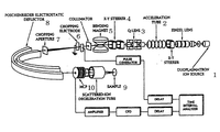
図5は,非特許文献1に示された従来技術にかかる中エネルギー同軸型直衝突イオン散乱分光装置の概念図である。
図において,イオン源1から発生した直流イオンビームは,加速管2やレンズ3,ステアラ4,偏向マグネット5などによりエネルギー付与,軌道調整,整形,不要イオンの除去などの手順を経て,チョッピング電極6に入射される。チョッピング電極6においては,パルス的に変化する電圧が印加されることでビームが進行方向に対して水平方向に軌道を曲げられることになる。したがって,チョッピング電極下流に設置されたチョッピングアパーチヤ7を通り抜けた直流のビームの一部のみがチョッピングアパーチャ7の下流に通過することになり,ビームがパルス化される。
パルス化されたビームはPoschenrieder電極8により収束とパルスの圧縮を経て試料9上に照射され,更に,試料9から発生する散乱イオンはMCP検出器10で捕捉される。その結果,散乱イオンのMCP検出器10上での検出位置と,試料からMCP検出器までの飛行時間とが測定される。
FIG. 5 is a conceptual diagram of a medium energy coaxial direct collision ion scattering spectrometer according to the prior art disclosed in Non-Patent
In the figure, a DC ion beam generated from an
The pulsed beam is irradiated on the
この測定時間はサンプルからMCP検出器10までの距離と散乱イオンのエネルギーにより決まり,上記試料からMCP検出器10まで距離は既知であるため散乱イオンのエネルギーを求め,これにより試料を分析することが可能となる。
しかしながら,上記非特許文献1に記載の従来技術においては,ビームのパルスを圧縮するためにPoschenrieder電極を用いているため装置が非常に大がかりとなる欠点がある。
This measurement time is determined by the distance from the sample to the
However, the conventional technique described in Non-Patent
一方,図6は,特許文献1の従来技術として紹介された散乱イオン分析装置の概念図であり,イオン源31からでたイオンはアパーチャ21と電極22を通過し,加速されてチョッピング電極13に至る。
チョッピング電極13内では,磁石12によって定磁場がかけられていて,イオンビームは図中矢印Cのように軌道を曲げられる。そこで,チョッピング電極13によって電場を形成すると,イオンの進行方向は曲げられ,所定の質量数のイオンのみがイオンビームとして試料5に導入される。
上記チョッピング電極13の電位を変えることで,目的のイオンを偏向させて試料方向へ進行させたり遮断したりできる,いわゆるチョッピングできる構成となっている。
試料の分析原理は,前記非特許文献1に記載されたものと同じである。
On the other hand, FIG. 6 is a conceptual diagram of the scattered ion analyzer introduced as the prior art of
In the chopping electrode 13, a constant magnetic field is applied by the magnet 12, and the ion beam is bent in the orbit as indicated by an arrow C in the figure. Therefore, when an electric field is formed by the chopping electrode 13, the traveling direction of the ions is bent, and only ions having a predetermined mass number are introduced into the
By changing the electric potential of the chopping electrode 13, so-called chopping can be performed, in which target ions can be deflected and advanced toward or away from the sample.
The analysis principle of the sample is the same as that described in
上記特許文献1の図2に記載の散乱イオン分析装置では,加速器により引出されたイオンビームは途中の平行平板電極(チョッピング電極)を通過する。この平行平板電極には,チョッピング電源からの高圧パルスが両電極間に印加されており周期的に変化する強電界がかかっている。従って,イオンビームは電界によって軌道を曲げられるが,所定のパルス電位の時に平行平板電極を通過したイオンビームのみが,下流の試料に導かれることになる。チョッピング電源のパルス出力はチョッピング回路の信号により制御される。
このようにパルス化されたイオンビームがそのまま試料に衝突し散乱され,検出器14で散乱イオンの飛行時間が測定される。
The pulsed ion beam collides with the sample as it is and is scattered, and the detector 14 measures the time of flight of the scattered ions.
ここでビームの長さΔtについて考える。実際にはΔtは1〜5ns程度である。ビームはこの時間の間試料に照射され続け,また散乱はどのタイミングでも起こりえるが,散乱の発生した時間は測定できないため時間分解能には,測定系の分解能などを考慮すると上記Δt以上となる。後述するように,時間幅Δtによる測定エネルギーの誤差ΔEは下式で表すことができる。
ΔE=2(6920.6/L)E√EΔt[s]
これよりエネルギー分解能は距離に反比例し時間分解能に比例することが判る。
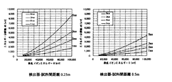
パラメータとしてビーム幅Δtを1〜5ns,L=0.25m,0.5mとし,この式から散乱イオンエネルギーに対するエネルギー分解能を計算した結果を図4に示す。
これによると検出器までの距離Lが0.5m,80keVの場合,ビーム長さが1ns異なるとエネルギー分解能は1keV程度と大きく変わることがわかる。
このようにエネルギー分解能を高めるには,例えば前記特許文献1の図1に記載のチョッパ板を高速で回転させればよいが,このような機械的な方法では高速化に限度がある。
Now consider the beam length Δt. In practice, Δt is about 1 to 5 ns. The beam continues to irradiate the sample during this time, and scattering can occur at any timing. However, since the time when the scattering occurs cannot be measured, the time resolution is greater than Δt in consideration of the resolution of the measurement system. As will be described later, the measurement energy error ΔE due to the time width Δt can be expressed by the following equation.
ΔE = 2 (6920.6 / L) E√EΔt [s]
This shows that the energy resolution is inversely proportional to the distance and proportional to the time resolution.
FIG. 4 shows the result of calculating the energy resolution with respect to the scattered ion energy from this equation, assuming that the beam width Δt is 1 to 5 ns, L = 0.25 m, and 0.5 m as parameters.
According to this, when the distance L to the detector is 0.5 m and 80 keV, the energy resolution changes greatly to about 1 keV when the beam length differs by 1 ns.
In order to increase the energy resolution in this way, for example, the chopper plate described in FIG. 1 of
従って,本発明が目的とするところは,イオンビームの先端及び/もしくは後端にかける電位を変化させることで,イオンビームを圧縮或いは伸張させることのできる飛行イオンビーム制御装置及び方法或いは,上記イオンビームの長さΔtを電子的制御により短くすることで,エネルギー分解能を高めることのできる散乱イオン分析装置を提供することである。 Accordingly, an object of the present invention is to provide a flying ion beam control apparatus and method capable of compressing or expanding an ion beam by changing a potential applied to the front end and / or rear end of the ion beam, or the ion ion beam. It is an object of the present invention to provide a scattered ion analyzer capable of increasing the energy resolution by shortening the beam length Δt by electronic control.
すなわち,上記のように散乱イオン分析装置において,エネルギー分解能を高めるには,測定対象物である試料に入射されるイオンビームの長さΔtを短くすることが有効であり,本発明はそのような目的を,電子制御により達成することのできる散乱イオン分析装置を提供しようとするものである。
また本発明は,上記のような散乱イオン分析装置のみでなく,飛行するイオンビームを飛行中において飛行方向に圧縮することのできるイオンビーム飛行制御装置及び方法を提供する。このイオンビーム飛行制御装置は,上記散乱イオン分析装置はもちろん,それ以外のイオンビームの飛行状態における飛行方向の長さを調整するあらゆる用途に適用可能であいり,イオンビームを圧縮する場合のみでなく,伸張する場合のも適用可能であることは言うまでも無い。
That is, in the scattered ion analyzer as described above, in order to increase the energy resolution, it is effective to shorten the length Δt of the ion beam incident on the sample that is the measurement object. It is an object of the present invention to provide a scattered ion analyzer that can achieve the object by electronic control.
In addition to the scattered ion analyzer as described above, the present invention provides an ion beam flight control apparatus and method capable of compressing a flying ion beam in the flight direction during flight. This ion beam flight control device can be applied not only to the above-mentioned scattered ion analyzer, but also to all other uses for adjusting the length of the flight direction of the ion beam in the flight state, not only for compressing the ion beam. Needless to say, the present invention can also be applied to the case of expansion.
上記目的を達成するべく本発明は,分析対象物に向けて飛行するイオンビームの飛行経路に,上記イオンビームが通過するパルス圧縮電極と,該パルス圧縮電極との間に所定の間隔をあけて上記イオンビームが通過する接地電極を設ける。そして,上記パルス圧縮電極に与える電位を,そこを通過するイオンビームの位置に応じて変化させるようにしたイオンビームの飛行制御装置が提供される。
この発明では,イオンビームを上記電極間を通過する間においてその先端及び/もしくは後端の速度を変化させるものであるので,イオンビームを前後或いはそのいずれかに伸張或いは圧縮させることで,飛行中のイオンビームの長さを変化させることが可能である。
In order to achieve the above object, the present invention provides a pulse compression electrode through which the ion beam passes and a predetermined interval between the pulse compression electrode and the pulse compression electrode through which the ion beam passes toward the analysis object. A ground electrode through which the ion beam passes is provided. An ion beam flight control apparatus is provided in which the potential applied to the pulse compression electrode is changed in accordance with the position of the ion beam passing therethrough.
In the present invention, the speed of the front end and / or the rear end is changed while the ion beam passes between the electrodes. It is possible to change the length of the ion beam.
先端のイオンを減速させると共に,イオンビームの後端を加速させることでイオンビームを圧縮させる具体的態様としては,上記パルス圧縮電極に印加される電圧を,上記イオンビームが該パルス圧縮電極に入射されかつ上記イオンビームの全体が上記パルス圧縮電極の開口部ビーム通路にすべて入射されるまでは第1の電位に維持し,上記イオンビーム先端が上記開口部ビーム通路から出射するまでに上記第1の電位よりも低い第2の電位に変化させるようにし,更に上記パルス圧縮電極に印加される電圧を,上記イオンビームが該パルス圧縮電極の開口部ビーム通路出口よりビーム全体が出射するまでに第2の低電位から上記第2の電位より高い第3の電位にまで上昇させ,上記イオンビーム全体が下流にある接地電極を通過するまで上記第3の電位に維持するようにしたイオンビームの飛行制御装置が挙げられる。
このように構成することで,イオンビームの前端が減速されると共に後端部が加速され,イオンビームの長さΔtを短くすることができる。これを散乱イオン分析装置に適用すれば,エネルギー分解能を高めることのできる。
As a specific mode of compressing the ion beam by decelerating the ions at the tip and accelerating the rear end of the ion beam, the voltage applied to the pulse compression electrode is applied to the pulse compression electrode. The first potential is maintained until the entire ion beam is incident on the opening beam passage of the pulse compression electrode, and the first potential is maintained until the tip of the ion beam is emitted from the opening beam passage. The voltage applied to the pulse compression electrode is changed to a second potential lower than the first potential before the ion beam is emitted from the exit beam passage exit of the pulse compression electrode. From a low potential of 2 to a third potential higher than the second potential and up until the entire ion beam passes through a ground electrode downstream. Flight control system of the ion beam so as to maintain the third potential and the like.
With this configuration, the front end of the ion beam is decelerated and the rear end is accelerated, and the length Δt of the ion beam can be shortened. If this is applied to a scattered ion analyzer, the energy resolution can be increased.
上記したイオンビームの先端を減速させることと,イオンビームの後端部を加速させることの両方を実行すれば更にイオンビームの長さΔtを短くすることができる。
そのための構成としては,上記パルス圧縮電極に与える電位を,上記イオンビームが該パルス圧縮電極の開口部ビーム通路入り口に差し掛かってからビーム全体が上記開口ビーム通路に入射するまでは第1の電位を保ち,ビーム全体が上記開口ビーム通路内にある間に上記第1の電位より低い第2の電位まで低下させ,その後ビーム全体が上記開口ビーム通路出口より出射するまでに上記第2の電位より高い第3の電位に上昇させ,上記イオンビーム先端が上記接地電極の出口に差し掛かるまで上記第3の電位を維持するようにしたイオンビームの飛行制御装置が提供される。
If both decelerating the tip of the ion beam and accelerating the rear end of the ion beam are performed, the length Δt of the ion beam can be further reduced.
For this purpose, the potential applied to the pulse compression electrode is the first potential from when the ion beam reaches the opening beam passage entrance of the pulse compression electrode until the entire beam enters the opening beam passage. Maintained and lowered to a second potential lower than the first potential while the entire beam is in the aperture beam path and then higher than the second potential until the entire beam exits from the aperture beam path exit An ion beam flight control apparatus is provided in which the third potential is raised to a third potential and the third potential is maintained until the tip of the ion beam reaches the exit of the ground electrode.
またこの装置をイオンビームの飛行制御方法として捉えると,分析対象物に向けて照射されたイオンビームの飛行経路に,上記イオンビームが通過するパルス圧縮電極と,該パルス圧縮電極との間に所定の間隔をあけて上記イオンビームが通過する接地電極を設け,上記パルス圧縮電極に印加される電圧を,上記イオンビームが該パルス圧縮電極に入射されかつ上記イオンビームの全体が上記パルス圧縮電極の開口部ビーム通路にすべて入射されるまでは第1の電位に維持し,上記イオンビーム先端が上記開口部ビーム通路から出射するまでに上記第1の電位よりも低い第2の電位に変化させるようにし,上記パルス圧縮電極に印加される電圧を,上記イオンビームが該パルス圧縮電極の開口部ビーム通路出口よりビーム全体が出射するまでに第2の低電位から上記第2の電位より高い 第3の電位にまで上昇させ,上記イオンビーム全体が下流にある接地電極を通過するまで上記第3の電位に維持するようにしたことを特徴とするイオンビームの飛行制御方法が把握される。
作用効果としては,前記イオンビームの飛行制御装置と同様である。
Further, if this apparatus is regarded as a flight control method of an ion beam, a predetermined interval is formed between the pulse compression electrode through which the ion beam passes and a pulse compression electrode on the flight path of the ion beam irradiated toward the analysis object. A ground electrode through which the ion beam passes is provided, and a voltage applied to the pulse compression electrode is set so that the ion beam is incident on the pulse compression electrode and the entire ion beam is applied to the pulse compression electrode. The first potential is maintained until all the light enters the aperture beam path, and the second potential is changed to a second potential lower than the first potential before the ion beam tip exits from the aperture beam path. The voltage applied to the pulse compression electrode is changed until the ion beam is emitted from the beam passage exit of the opening of the pulse compression electrode. The second potential is raised from the second low potential to a third potential higher than the second potential, and is maintained at the third potential until the entire ion beam passes through a ground electrode located downstream. The ion beam flight control method is grasped.
The effect is the same as that of the ion beam flight control device.
上記イオンビームの飛行制御装置の適用例として,典型的には次に記載する散乱イオン分析装置が挙げられる。但し,このイオンビーム飛行制御装置や方法の適用範囲は,上記散乱イオン分析装置に限らず,イオンビームを飛行させて行う各種の検査装置,各種の駆動装置そのほかにも適用可能であることは,いうまでもない。 A typical example of application of the ion beam flight control apparatus is a scattered ion analyzer described below. However, the application range of this ion beam flight control device and method is not limited to the above-mentioned scattered ion analyzer, but can be applied to various inspection devices, various drive devices, etc., which are performed by flying an ion beam. Needless to say.
上記イオンビーム飛行制御装置を適用した散乱イオン分析装置としては,加速器からの入射イオンビームのビーム軸と平行に設置され,パルス電圧を印加される2枚の平行平板電極と,上記平行平板電極の下流に設置されたアパーチヤとを備え,上記アパーチヤによってパルス化された後分析対象物に入射し,分析対象物表面の元素により散乱される該イオンの飛行時間を測定することで,分析対象物の深さ方向の元素組成分析を行う散乱イオン分析装置において,前記分析対象物に向けて飛行するイオンビームの飛行経路に,上記イオンビームが通過するパルス圧縮電極と,該パルス圧縮電極との間に所定の間隔をあけて上記イオンビームが通過する接地電極を設け,上記パルス圧縮電極に与える電位を,そこを通過するイオンビームの位置に応じて変化させるようにしたことを特徴とする散乱イオン分析装置が考えられる。 The scattered ion analyzer to which the ion beam flight control device is applied includes two parallel plate electrodes that are installed in parallel with the beam axis of the incident ion beam from the accelerator and to which a pulse voltage is applied, and An aperture installed downstream, and after being pulsed by the aperture, incident on the analyte and measuring the time of flight of the ions scattered by the elements on the analyte surface. In a scattered ion analyzer that performs an elemental composition analysis in the depth direction, a pulse compression electrode through which the ion beam passes in a flight path of the ion beam flying toward the analysis object, and the pulse compression electrode A ground electrode through which the ion beam passes is provided at a predetermined interval, and the potential applied to the pulse compression electrode is determined by the position of the ion beam passing therethrough. Scattered ions analyzer is considered which is characterized in that so as to vary in accordance with the.
或いは,これを更に具体化させた,加速器からの入射イオンビームのビーム軸と平行に設置され,パルス電圧を印加される2枚の平行平板電極と,上記平行平板電極の下流に設置されたアパーチヤとを備え,上記アパーチヤによってパルス化された後分析対象物に入射し,分析対象物表面の元素により散乱される該イオンの飛行時間を測定することで,分析対象物の深さ方向の元素組成分析を行う散乱イオン分析装置において,前記分析対象物に向けて飛行するイオンビームの飛行経路に,上記イオンビームが通過するパルス圧縮電極と,該パルス圧縮電極との間に所定の間隔をあけて上記イオンビームが通過する接地電極を設け,上記パルス圧縮電極に印加される電圧を,上記イオンビームが該パルス圧縮電極に入射されかつ上記イオンビームの全体が上記パルス圧縮電極の開口部ビーム通路にすべて入射されるまでは第1の電位に維持し,上記イオンビーム先端が上記開口部ビーム通路から出射するまでに上記第1の電位よりも低い第2の電位に変化させるようにし,上記パルス圧縮電極に印加される電圧を,上記イオンビームが該パルス圧縮電極の開口部ビーム通路出口よりビーム全体が出射するまでに第2の低電位から上記第2の電位より高い第3の電位にまで上昇させ,上記イオンビーム全体が下流にある接地電極を通過するまで上記第3の電位に維持するようにした散乱イオン分析装置が考えられる。 Alternatively, two more parallel plate electrodes installed in parallel with the beam axis of the incident ion beam from the accelerator and applied with a pulse voltage, and an aperture installed downstream of the parallel plate electrode, which are further embodied. An element composition in the depth direction of the analyte by measuring the time of flight of the ions incident on the analyte after being pulsed by the aperture and scattered by the elements on the analyte surface In a scattered ion analyzer that performs analysis, a predetermined interval is provided between a pulse compression electrode through which the ion beam passes and a pulse compression electrode on a flight path of the ion beam that is flying toward the analysis object. A ground electrode through which the ion beam passes is provided, and a voltage applied to the pulse compression electrode is set so that the ion beam is incident on the pulse compression electrode and the ion beam is applied. Is maintained at the first potential until all of the beam is incident on the aperture beam path of the pulse compression electrode, and more than the first potential until the ion beam tip exits from the aperture beam path. The voltage applied to the pulse compression electrode is changed from the second low potential until the whole beam is emitted from the exit beam passage exit of the pulse compression electrode. A scattered ion analyzer that can be raised to a third potential higher than the second potential and maintained at the third potential until the entire ion beam passes through a downstream ground electrode can be considered.
本発明は,上記のように構成されているので,イオンビームに速度差をつけ(速度分布をもたせ)イオンビームの長さΔtを電子的制御により短くすることで,簡単にイオンビームの圧縮を行うことができる。この場合,機械的構成によらないので,極めて高速化することができる。またそれによりエネルギー分解能を高めることのできる散乱イオン分析装置を提供することができる。 Since the present invention is configured as described above, it is possible to easily compress the ion beam by adding a velocity difference to the ion beam (providing a velocity distribution) and shortening the ion beam length Δt by electronic control. It can be carried out. In this case, since it does not depend on a mechanical configuration, the speed can be extremely increased. Moreover, the scattered ion analyzer which can improve energy resolution by it can be provided.
以下,本発明を具体化した実施形態に基づいて,本発明を詳しく説明する。
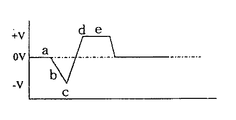
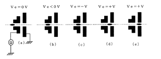
ここに図1は,本発明の一実施形態にかかる散乱イオン分析装置の概念図,図2,図3は,上記散乱イオン分析装置を構成するパルス圧縮電極におけるイオンビームの移動位置と,その時々のパルス圧縮電極への印加電圧の変化を示す概念図である。
図1に示された散乱イオン分析装置では,図示しない加速器により引出されたイオンビームは,途中の平行平板電極41を通過する。この平行平板電極41にはチョッピング電源43からの高圧パルスが両電極間に印加されている。これによって上記平行平板電極41には周期的に変化する強電界が発生する。
平行平板電極を通過するイオンビームは,上記電界によって軌道を曲げられるが,パルス電位が0Vの時はそのまま直進する。実際には0±ΔV程度の電圧印加時のビームが通過することになるためパルスは数ns程度の幅を持つ。
Hereinafter, the present invention will be described in detail based on embodiments embodying the present invention.
Here, FIG. 1 is a conceptual diagram of a scattered ion analyzer according to an embodiment of the present invention, and FIGS. 2 and 3 are positions of the ion beam on the pulse compression electrode constituting the scattered ion analyzer, and sometimes It is a conceptual diagram which shows the change of the applied voltage to the pulse compression electrode.
In the scattered ion analyzer shown in FIG. 1, an ion beam extracted by an accelerator (not shown) passes through a parallel plate electrode 41 in the middle. A high voltage pulse from a chopping
The ion beam passing through the parallel plate electrode is bent in the orbit by the electric field, but goes straight when the pulse potential is 0V. Actually, the beam passes when a voltage of about 0 ± ΔV is applied, so the pulse has a width of about several ns.
上記平行平板電極41を通過したイオンビームは,その下流にあるスリットを備えたアパーチャ45で選別されることになり,パルス電位が0V近辺の短い時間帯に通過したパルスイオンビームのみが,下流に導かれることになる。
上記チョッピング電源43のパルス出力は別に設けた図外の同期回路の信号により制御される。
The ion beam that has passed through the parallel plate electrode 41 is selected by an aperture 45 having a slit downstream thereof, and only the pulse ion beam that has passed through a short time zone in which the pulse potential is near 0 V is downstream. Will be guided.
The pulse output of the chopping
ここでイオンをHe+,エネルギーE0を100keVと仮定すると,ビームの速度は2,188,470m/sであり,1nsあたりのビーム長さは2.19mmである。
なお,この実施形態では,時間分解能が装置の性能に直接関与する。このように,性能の把握を容易とするために,パルス化したビーム長さについては,時間で表している。
このようにパルス化されたイオンビームがそのまま試料47に衝突し散乱され,イオン検出器49で検出される。この時の散乱イオンの飛行時間を測定した場合のエネルギー分解能について考察する。
イオンの速度は
ν=√((2eE)/m) …(1)
と表せる。ここに,e:電荷,E:散乱イオンエネルギー,m:イオン質量である。
Assuming that the ion is He + and the energy E0 is 100 keV, the beam speed is 2,188,470 m / s, and the beam length per ns is 2.19 mm.
In this embodiment, the time resolution is directly related to the performance of the apparatus. As described above, in order to easily understand the performance, the pulsed beam length is expressed in time.
The ion beam thus pulsed collides with the sample 47 as it is and is scattered and detected by the
The velocity of ions is ν = √ ((2eE) / m) (1)
It can be expressed. Here, e: charge, E: scattered ion energy, m: ion mass.
He+のe,mの値を入れると,上式は
ν=6920.6√E[m/s] …(2)
である。ここで試料から検出器までの距離をLとすると,その間の飛行時間は
t=L/ν=L/(6920.6√E)[s] …(3)
となる。エネルギーがΔE大きな粒子の飛行時間は同様に
t´=L/ν´=L/(6920.6√(E+ΔE))[s] …(4)
である。従って,飛行時間の差Δtは
Δt=L/6920.6((1/√E)−(1/(√(E+ΔE))…(5)
である。ここで(5)式を近似すると
Δt=(L/6920.6)・(ΔE/(2E√E) …(6)
となる。時間差は距離およびエネルギー差に比例し,イオンエネルギーの1.5乗に反比例する。
When the values of e and m of He + are entered, the above equation is ν = 69200.6√E [m / s] (2)
It is. Here, when the distance from the sample to the detector is L, the flight time between them is t = L / ν = L / (6920.6√E) [s] (3)
It becomes. Similarly, the flight time of particles with a large energy ΔE is t ′ = L / ν ′ = L / (6920.6√ (E + ΔE)) [s] (4)
It is. Therefore, the difference Δt in flight time is Δt = L / 6920.6 ((1 / √E) − (1 / (√ (E + ΔE))) (5)
It is. When equation (5) is approximated here, Δt = (L / 6920.6) · (ΔE / (2E√E) (6)
It becomes. The time difference is proportional to the distance and the energy difference, and inversely proportional to the ion energy to the power of 1.5.
この近似式は,30keV以上で(5)式に対して3%以下,75keV以上で1%以下の誤差である。
ここでビームの長さΔtと考える。実際には1〜5ns程度である。ビームはこの時間の間試料に照射され続け,また,散乱はどのタイミングでも起こりえるが,散乱の発生した時間は測定できないため,時間分解能は,測定系の分解能などを考慮すると上記Δt以上となる。(6)式を変形すると,時間幅Δtによる測定エネルギーの誤差ΔEは(7)式で表すことができる。
ΔE=2(6920.6/L)E√EΔt[s] …(7)
この式からエネルギー分解能は距離に反比例し時間分解能に比例することが判る。
This approximate expression is an error of 30 keV or more and 3% or less with respect to the expression (5) and 75 keV or more and 1% or less.
Here, the beam length Δt is considered. Actually, it is about 1 to 5 ns. The beam continues to irradiate the sample during this time, and scattering can occur at any timing, but the time at which the scattering has occurred cannot be measured. Therefore, the time resolution is greater than Δt in consideration of the resolution of the measurement system, etc. . By transforming equation (6), the measurement energy error ΔE due to the time width Δt can be expressed by equation (7).
ΔE = 2 (6920.6 / L) E√EΔt [s] (7)
From this equation, it can be seen that the energy resolution is inversely proportional to the distance and proportional to the time resolution.
この式から散乱イオンエネルギーに対するエネルギー分解能を計算しする。パラメータとしてビーム幅Δtを1〜5ns,L=0.25m及び0.5mの2段階とした結果が図4に示されている。
これによると検出器までの距離Lが0.5m,80keVの場合,ビーム長さが1ns異なるとエネルギー分解能は1keV程度変わる。
上記のようにエネルギー分解能が,飛行中のイオンビーム長さによることから,本発明では,以下に述べるように,上記飛行中のイオンビームに電界を作用させて,イオンビームを圧縮しその長さを短くして,エネルギー分解能を向上させる。
The energy resolution for the scattered ion energy is calculated from this equation. FIG. 4 shows the result of setting the beam width Δt as parameters in two stages of 1 to 5 ns, L = 0.25 m, and 0.5 m.
According to this, when the distance L to the detector is 0.5 m and 80 keV, the energy resolution changes by about 1 keV if the beam length differs by 1 ns.
Since the energy resolution depends on the length of the ion beam in flight as described above, the present invention compresses the ion beam by compressing the ion beam by applying an electric field to the ion beam in flight as described below. To improve energy resolution.
すなわち,図1に示すように,アパーチャ45の下流にパルス圧縮電極51およびこれと所定の間隔をあけて接地電極53を設ける。
また,それに対して図2及び図3に示すように,上記エネルギーE0で入射する長さ数nsのイオンビーム先端が,上記パルス圧縮電極51の開口部ビーム通路55の入り口51aに差し掛かってから,イオンビーム全体が開口部ビーム通路55に入射するまで,および,イオンビームがパルス圧縮電極51内に完全に入ってしまうまでは,上記パルス圧縮電極51に印加される電圧を,ずっと0Vの状態(aの状態)に維持する。
イオンビームが上記パルス圧縮電極51内に完全に入ってしまった後に,上記電圧を低下させ(bの状態),ビームの先端が上記パルス圧縮電極51から顔を出すまでの間(イオンビーム全体が開口部ビーム通路55内にすべて収まっている間)に最低の,例えば−100Vまで低下させる(cの状態)。
その後イオンビームの先端が上記パルス圧縮電極51の出口51bから出る直前から,電圧を例えば+100Vまで上昇させ(dの状態),イオンビームのすべてが上記接地電極53内に入りきるまでは,電圧上昇状態を保つ。上昇速度は,イオンビームの長さと同じ程度とする。イオンビームは,上記電圧がマイナスの場合減速し,+の場合加速される。イオンビームが上記接地電極53内に完全に入ってしまった後は,電圧を一定又は低下させる。
最後に,イオンビームが上記接地電極53から出て行くとき(eの状態)に電圧は低下していき,やがて最初の状態に戻る。
なお,上記実施形態では,第3の電位は,第1の電位より高電位としているが,第1の電位より低くしてもよく,負電位とすることも可能である。また,第1の電位は,0電位以外であっても良い。
That is, as shown in FIG. 1, a pulse compression electrode 51 and a
On the other hand, as shown in FIGS. 2 and 3, after the tip of the ion beam having a length of several ns incident with the energy E0 reaches the entrance 51a of the opening beam passage 55 of the pulse compression electrode 51, Until the entire ion beam enters the aperture beam passage 55 and until the ion beam completely enters the pulse compression electrode 51, the voltage applied to the pulse compression electrode 51 is kept at a state of 0V ( a).
After the ion beam has completely entered the pulse compression electrode 51, the voltage is decreased (state b) until the tip of the beam comes out of the pulse compression electrode 51 (the entire ion beam is The voltage is lowered to the lowest value, for example, −100 V (while being all within the aperture beam passage 55) (state c).
Thereafter, immediately before the tip of the ion beam exits from the
Finally, when the ion beam exits from the ground electrode 53 (state e), the voltage decreases and eventually returns to the initial state.
In the above embodiment, the third potential is higher than the first potential, but may be lower than the first potential or may be a negative potential. The first potential may be other than zero potential.
従って,ビームの先端部ではビームエネルギーは100eV減り,後端部では100eV増えることになる。これは,イオンビームの速度が先端部で遅くなり後端部で早くなる,すなわちイオンビーム長が前後に圧縮されることであり,1mイオンビームが進行した場合に,イオンビーム長さは0.9ns短くなる。すなわち,図1におけるLlの距離進行したときにはLl*0.9nsのパルス圧縮が図られることになる。 Accordingly, the beam energy is reduced by 100 eV at the front end of the beam and increased by 100 eV at the rear end. This means that the speed of the ion beam becomes slower at the front end and faster at the rear end, that is, the ion beam length is compressed back and forth, and when the 1 m ion beam travels, the ion beam length is 0. 9ns shorter. That is, when the distance of L1 in FIG. 1 is advanced, pulse compression of L1 * 0.9 ns is achieved.
この時イオンビームは±100V=200Vのエネルギーの広がりを持つことになり,散乱イオンも200eVエネルギー幅が大きくなることになるが,ビーム圧縮の効果でたとえば1ns圧縮されると1keVエネルギー幅が小さくなるため測定の分解能は大幅に向上する。
なお,上記の説明では,パルス圧縮電極と接地電極を1組だけ設けた場合について説明したが,これらの電極の組を複数組設けて,イオンビームを多段に圧縮或いは伸張するようなことも可能である。
以上の説明では,イオンビームの圧縮によるエネルギー分解能向上にだけ着目したが,元の切り出すパルス幅を長くしておき,圧縮により数nsにすることでビーム電流密度を上げ,散乱イオンの収量を増加させるという利用法も考えられることを付記しておく。
At this time, the ion beam has an energy spread of ± 100 V = 200 V, and the scattered ions also have a 200 eV energy width. However, for example, when compressed by 1 ns due to the effect of beam compression, the 1 keV energy width decreases. Therefore, the measurement resolution is greatly improved.
In the above description, the case where only one set of pulse compression electrode and ground electrode is provided has been described. However, a plurality of sets of these electrodes may be provided to compress or expand the ion beam in multiple stages. It is.
In the above explanation, we focused only on improving the energy resolution by compressing the ion beam, but increasing the beam current density and increasing the yield of scattered ions by increasing the original pulse width and setting it to a few ns by compression. It should be noted that there is a possibility of using it.
41…平行平板電極
43…チョッピング電極
45…アパーチャ
47…試料(分析対象物)
49…イオン検出器
51…パルス圧縮電極
51a…出口
53…接地電極
55…開口部ビーム通路
41 ...
49 ... Ion detector 51 ... Pulse compression electrode 51a ...
Claims (5)
上記平行平板電極の下流に設置されたアパーチヤとを備え,
上記アパーチヤによってパルス化された後分析対象物に入射し,分析対象物表面の元素により散乱される該イオンの飛行時間を測定することで,分析対象物の深さ方向の元素組成分析を行う散乱イオン分析装置において,
前記分析対象物に向けて飛行するイオンビームの飛行経路に,上記イオンビームが通過するパルス圧縮電極と,該パルス圧縮電極との間に所定の間隔をあけて上記イオンビームが通過する接地電極を設け,上記パルス圧縮電極に与える電位を,そこを通過するイオンビームの位置に応じて変化させるようにしたことを特徴とする散乱イオン分析装置。 Two parallel plate electrodes installed parallel to the beam axis of the incident ion beam from the accelerator and applied with a pulse voltage;
An aperture installed downstream of the parallel plate electrode,
Scattering that performs elemental composition analysis in the depth direction of the analyte by measuring the time of flight of the ions incident on the analyte after being pulsed by the aperture and scattered by the elements on the analyte surface In ion analyzer,
A pulse compression electrode through which the ion beam passes, and a ground electrode through which the ion beam passes through the pulse compression electrode in a flight path of the ion beam flying toward the analysis object. A scattered ion analyzer, characterized in that the potential applied to the pulse compression electrode is changed in accordance with the position of an ion beam passing therethrough.
上記平行平板電極の下流に設置されたアパーチヤとを備え,
上記アパーチヤによってパルス化された後分析対象物に入射し,分析対象物表面の元素により散乱される該イオンの飛行時間を測定することで,分析対象物の深さ方向の元素組成分析を行う散乱イオン分析装置において,
分析対象物に向けて照射されたイオンビームの飛行経路に,上記イオンビームが通過し開口ビーム通路を形成するパルス圧縮電極と,該パルス圧縮電極との間に所定の間隔をあけて上記イオンビームが通過する接地電極を設け,上記パルス圧縮電極に印加される電圧を,上記イオンビームが該パルス圧縮電極に入射されかつ上記イオンビームの全体が上記パルス圧縮電極の開口部ビーム通路にすべて入射されるまでは第1の電位に維持し,上記イオンビーム先端が上記開口部ビーム通路から出射するまでに上記第1の電位よりも低い第2の電位に変化させるようにし、上記パルス圧縮電極に印加される電圧を,上記イオンビームが該パルス圧縮電極の開口部ビーム通路出口よりビーム全体が出射するまでに第2の低電位から上記第2の電位より高い第3の電位にまで上昇させ,上記イオンビーム全体が下流にある接地電極を通過するまで上記第3の電位に維持するようにしたことを特徴とする散乱イオン分析装置。 Two parallel plate electrodes installed parallel to the beam axis of the incident ion beam from the accelerator and applied with a pulse voltage;
An aperture installed downstream of the parallel plate electrode,
Scattering that performs elemental composition analysis in the depth direction of the analyte by measuring the time of flight of the ions incident on the analyte after being pulsed by the aperture and scattered by the elements on the analyte surface In ion analyzer,
A pulse compression electrode through which the ion beam passes and forms an aperture beam path in the flight path of the ion beam irradiated toward the object to be analyzed, and the ion beam at a predetermined interval between the pulse compression electrode A ground electrode through which the ion beam passes, and the voltage applied to the pulse compression electrode is applied to the pulse compression electrode, and the entire ion beam is incident on the opening beam path of the pulse compression electrode. Until the ion beam tip exits from the aperture beam path, the first potential is changed to a second potential lower than the first potential and applied to the pulse compression electrode. The voltage from the second low potential to the second potential before the ion beam exits from the exit beam passage exit of the pulse compression electrode. High until the third potential is raised, the ion beam across the scattered ion analysis apparatus is characterized in that in order to maintain to the third potential so as to pass through a ground electrode located downstream.
Priority Applications (1)
| Application Number | Priority Date | Filing Date | Title |
|---|---|---|---|
| JP2006125277A JP2007299570A (en) | 2006-04-28 | 2006-04-28 | Flight control device of ion beam, flight control method of ion beam and dispersed ion analyzer |
Applications Claiming Priority (1)
| Application Number | Priority Date | Filing Date | Title |
|---|---|---|---|
| JP2006125277A JP2007299570A (en) | 2006-04-28 | 2006-04-28 | Flight control device of ion beam, flight control method of ion beam and dispersed ion analyzer |
Publications (1)
| Publication Number | Publication Date |
|---|---|
| JP2007299570A true JP2007299570A (en) | 2007-11-15 |
Family
ID=38768901
Family Applications (1)
| Application Number | Title | Priority Date | Filing Date |
|---|---|---|---|
| JP2006125277A Pending JP2007299570A (en) | 2006-04-28 | 2006-04-28 | Flight control device of ion beam, flight control method of ion beam and dispersed ion analyzer |
Country Status (1)
| Country | Link |
|---|---|
| JP (1) | JP2007299570A (en) |
Cited By (2)
| Publication number | Priority date | Publication date | Assignee | Title |
|---|---|---|---|---|
| JP2012099221A (en) * | 2010-10-29 | 2012-05-24 | Ulvac Japan Ltd | Gas cluster ion beam gun, surface analysis device and surface analytical method |
| CN119880972A (en) * | 2025-02-25 | 2025-04-25 | 上海交通大学 | Terahertz driven femtosecond electronic pulse chopping and compressing device |
Citations (8)
| Publication number | Priority date | Publication date | Assignee | Title |
|---|---|---|---|---|
| JPH05273154A (en) * | 1992-03-27 | 1993-10-22 | Shimadzu Corp | Ion scattering spectrometer |
| JPH0666999A (en) * | 1992-08-21 | 1994-03-11 | Ishikawajima Harima Heavy Ind Co Ltd | Pulsing device for low speed positron |
| JPH0743325A (en) * | 1993-07-30 | 1995-02-14 | Shimadzu Corp | Ion scattering spectrometer |
| JPH1116532A (en) * | 1997-06-24 | 1999-01-22 | Shimadzu Corp | Ion scattering spectral apparatus |
| JPH11311700A (en) * | 1999-02-19 | 1999-11-09 | Sumitomo Heavy Ind Ltd | Charged particle beam aggregating method |
| JP2000338300A (en) * | 1999-05-27 | 2000-12-08 | Sumitomo Heavy Ind Ltd | Method and device for bunching charged particle beam |
| JP2002184349A (en) * | 2000-12-14 | 2002-06-28 | Shimadzu Corp | Ion trap type mass spectrometer |
| JP2003151487A (en) * | 2001-11-09 | 2003-05-23 | Shimadzu Corp | Time-of-flight mass spectrometer |
-
2006
- 2006-04-28 JP JP2006125277A patent/JP2007299570A/en active Pending
Patent Citations (8)
| Publication number | Priority date | Publication date | Assignee | Title |
|---|---|---|---|---|
| JPH05273154A (en) * | 1992-03-27 | 1993-10-22 | Shimadzu Corp | Ion scattering spectrometer |
| JPH0666999A (en) * | 1992-08-21 | 1994-03-11 | Ishikawajima Harima Heavy Ind Co Ltd | Pulsing device for low speed positron |
| JPH0743325A (en) * | 1993-07-30 | 1995-02-14 | Shimadzu Corp | Ion scattering spectrometer |
| JPH1116532A (en) * | 1997-06-24 | 1999-01-22 | Shimadzu Corp | Ion scattering spectral apparatus |
| JPH11311700A (en) * | 1999-02-19 | 1999-11-09 | Sumitomo Heavy Ind Ltd | Charged particle beam aggregating method |
| JP2000338300A (en) * | 1999-05-27 | 2000-12-08 | Sumitomo Heavy Ind Ltd | Method and device for bunching charged particle beam |
| JP2002184349A (en) * | 2000-12-14 | 2002-06-28 | Shimadzu Corp | Ion trap type mass spectrometer |
| JP2003151487A (en) * | 2001-11-09 | 2003-05-23 | Shimadzu Corp | Time-of-flight mass spectrometer |
Cited By (2)
| Publication number | Priority date | Publication date | Assignee | Title |
|---|---|---|---|---|
| JP2012099221A (en) * | 2010-10-29 | 2012-05-24 | Ulvac Japan Ltd | Gas cluster ion beam gun, surface analysis device and surface analytical method |
| CN119880972A (en) * | 2025-02-25 | 2025-04-25 | 上海交通大学 | Terahertz driven femtosecond electronic pulse chopping and compressing device |
Similar Documents
| Publication | Publication Date | Title |
|---|---|---|
| DE69935517T2 (en) | Time-of | |
| EP0905743A1 (en) | Ion source and accelerator for improved dynamic range and mass selection in a time of flight mass spectrometer | |
| JP4182844B2 (en) | Mass spectrometer | |
| CN102099892B (en) | TOF mass spectrometer for stigmatic imaging and associated method | |
| JP5723893B2 (en) | Mass spectrometer and ion separation detection method | |
| JP2567736B2 (en) | Ion scattering analyzer | |
| US5164592A (en) | Method and apparatus for mass spectrometric analysis | |
| Ter-Avetisyan et al. | Time resolved corpuscular diagnostics of plasmas produced with high-intensity femtosecond laser pulses | |
| JP4506481B2 (en) | Time-of-flight mass spectrometer | |
| CN103531432A (en) | Pulsed ion source, mass spectrometer and method for generating ions | |
| JP4606270B2 (en) | Time-of-flight measurement device for sample ions, time-of-flight mass spectrometer, time-of-flight mass spectrometry method | |
| JP2007299570A (en) | Flight control device of ion beam, flight control method of ion beam and dispersed ion analyzer | |
| US5182453A (en) | Ion scattering spectrometer | |
| JP2942815B2 (en) | Particle selection method and time-of-flight type selection type particle analyzer | |
| JP3303587B2 (en) | Mass spectrometer and ion source | |
| US20250006483A1 (en) | Method of optimizing geometric and electrostatic parameters of an electrostatic linear ion trap (elit) | |
| JPS61195554A (en) | Time of flight type mass spectrometer | |
| JP5553308B2 (en) | Light element analyzer and analysis method | |
| RU2658293C1 (en) | Time-of-flight plasma ion spectrometer | |
| RU2266587C1 (en) | Ion spectrum measurement process and transit-time ion spectrometer | |
| JP4368698B2 (en) | Sample analyzer and method thereof | |
| US20070057177A1 (en) | Non-linear ion post-focusing apparatus and mass spectrometer using the same | |
| JPH02165038A (en) | Time-of-flight particle analyzer | |
| JP6292565B2 (en) | Particle analysis method and particle analyzer | |
| JPH02158048A (en) | mass spectrometer |
Legal Events
| Date | Code | Title | Description |
|---|---|---|---|
| A621 | Written request for application examination |
Free format text: JAPANESE INTERMEDIATE CODE: A621 Effective date: 20080926 |
|
| A977 | Report on retrieval |
Free format text: JAPANESE INTERMEDIATE CODE: A971007 Effective date: 20110210 |
|
| A131 | Notification of reasons for refusal |
Free format text: JAPANESE INTERMEDIATE CODE: A131 Effective date: 20110215 |
|
| A02 | Decision of refusal |
Free format text: JAPANESE INTERMEDIATE CODE: A02 Effective date: 20110705 |