JP2007503684A - 高圧放電ランプのためのランプベースおよび高圧放電ランプ - Google Patents
高圧放電ランプのためのランプベースおよび高圧放電ランプ Download PDFInfo
- Publication number
- JP2007503684A JP2007503684A JP2006524213A JP2006524213A JP2007503684A JP 2007503684 A JP2007503684 A JP 2007503684A JP 2006524213 A JP2006524213 A JP 2006524213A JP 2006524213 A JP2006524213 A JP 2006524213A JP 2007503684 A JP2007503684 A JP 2007503684A
- Authority
- JP
- Japan
- Prior art keywords
- pressure discharge
- ring
- contact element
- mounting substrate
- discharge lamp
- Prior art date
- Legal status (The legal status is an assumption and is not a legal conclusion. Google has not performed a legal analysis and makes no representation as to the accuracy of the status listed.)
- Pending
Links
Images


Classifications
-
- H—ELECTRICITY
- H01—ELECTRIC ELEMENTS
- H01R—ELECTRICALLY-CONDUCTIVE CONNECTIONS; STRUCTURAL ASSOCIATIONS OF A PLURALITY OF MUTUALLY-INSULATED ELECTRICAL CONNECTING ELEMENTS; COUPLING DEVICES; CURRENT COLLECTORS
- H01R33/00—Coupling devices specially adapted for supporting apparatus and having one part acting as a holder providing support and electrical connection via a counterpart which is structurally associated with the apparatus, e.g. lamp holders; Separate parts thereof
- H01R33/05—Two-pole devices
- H01R33/18—Two-pole devices having only abutting contacts
-
- H—ELECTRICITY
- H01—ELECTRIC ELEMENTS
- H01J—ELECTRIC DISCHARGE TUBES OR DISCHARGE LAMPS
- H01J5/00—Details relating to vessels or to leading-in conductors common to two or more basic types of discharge tubes or lamps
- H01J5/50—Means forming part of the tube or lamps for the purpose of providing electrical connection to it
-
- F—MECHANICAL ENGINEERING; LIGHTING; HEATING; WEAPONS; BLASTING
- F21—LIGHTING
- F21V—FUNCTIONAL FEATURES OR DETAILS OF LIGHTING DEVICES OR SYSTEMS THEREOF; STRUCTURAL COMBINATIONS OF LIGHTING DEVICES WITH OTHER ARTICLES, NOT OTHERWISE PROVIDED FOR
- F21V23/00—Arrangement of electric circuit elements in or on lighting devices
-
- H—ELECTRICITY
- H01—ELECTRIC ELEMENTS
- H01J—ELECTRIC DISCHARGE TUBES OR DISCHARGE LAMPS
- H01J5/00—Details relating to vessels or to leading-in conductors common to two or more basic types of discharge tubes or lamps
- H01J5/50—Means forming part of the tube or lamps for the purpose of providing electrical connection to it
- H01J5/54—Means forming part of the tube or lamps for the purpose of providing electrical connection to it supported by a separate part, e.g. base
-
- H—ELECTRICITY
- H01—ELECTRIC ELEMENTS
- H01J—ELECTRIC DISCHARGE TUBES OR DISCHARGE LAMPS
- H01J61/00—Gas-discharge or vapour-discharge lamps
- H01J61/02—Details
- H01J61/56—One or more circuit elements structurally associated with the lamp
-
- H—ELECTRICITY
- H05—ELECTRIC TECHNIQUES NOT OTHERWISE PROVIDED FOR
- H05K—PRINTED CIRCUITS; CASINGS OR CONSTRUCTIONAL DETAILS OF ELECTRIC APPARATUS; MANUFACTURE OF ASSEMBLAGES OF ELECTRICAL COMPONENTS
- H05K1/00—Printed circuits
- H05K1/02—Details
- H05K1/0213—Electrical arrangements not otherwise provided for
- H05K1/0254—High voltage adaptations; Electrical insulation details; Overvoltage or electrostatic discharge protection ; Arrangements for regulating voltages or for using plural voltages
-
- H—ELECTRICITY
- H05—ELECTRIC TECHNIQUES NOT OTHERWISE PROVIDED FOR
- H05K—PRINTED CIRCUITS; CASINGS OR CONSTRUCTIONAL DETAILS OF ELECTRIC APPARATUS; MANUFACTURE OF ASSEMBLAGES OF ELECTRICAL COMPONENTS
- H05K3/00—Apparatus or processes for manufacturing printed circuits
- H05K3/10—Apparatus or processes for manufacturing printed circuits in which conductive material is applied to the insulating support in such a manner as to form the desired conductive pattern
- H05K3/20—Apparatus or processes for manufacturing printed circuits in which conductive material is applied to the insulating support in such a manner as to form the desired conductive pattern by affixing prefabricated conductor pattern
- H05K3/202—Apparatus or processes for manufacturing printed circuits in which conductive material is applied to the insulating support in such a manner as to form the desired conductive pattern by affixing prefabricated conductor pattern using self-supporting metal foil pattern
-
- F—MECHANICAL ENGINEERING; LIGHTING; HEATING; WEAPONS; BLASTING
- F21—LIGHTING
- F21S—NON-PORTABLE LIGHTING DEVICES; SYSTEMS THEREOF; VEHICLE LIGHTING DEVICES SPECIALLY ADAPTED FOR VEHICLE EXTERIORS
- F21S41/00—Illuminating devices specially adapted for vehicle exteriors, e.g. headlamps
- F21S41/10—Illuminating devices specially adapted for vehicle exteriors, e.g. headlamps characterised by the light source
- F21S41/19—Attachment of light sources or lamp holders
- F21S41/192—Details of lamp holders, terminals or connectors
-
- H—ELECTRICITY
- H01—ELECTRIC ELEMENTS
- H01R—ELECTRICALLY-CONDUCTIVE CONNECTIONS; STRUCTURAL ASSOCIATIONS OF A PLURALITY OF MUTUALLY-INSULATED ELECTRICAL CONNECTING ELEMENTS; COUPLING DEVICES; CURRENT COLLECTORS
- H01R33/00—Coupling devices specially adapted for supporting apparatus and having one part acting as a holder providing support and electrical connection via a counterpart which is structurally associated with the apparatus, e.g. lamp holders; Separate parts thereof
- H01R33/945—Holders with built-in electrical component
-
- H—ELECTRICITY
- H05—ELECTRIC TECHNIQUES NOT OTHERWISE PROVIDED FOR
- H05K—PRINTED CIRCUITS; CASINGS OR CONSTRUCTIONAL DETAILS OF ELECTRIC APPARATUS; MANUFACTURE OF ASSEMBLAGES OF ELECTRICAL COMPONENTS
- H05K2201/00—Indexing scheme relating to printed circuits covered by H05K1/00
- H05K2201/03—Conductive materials
- H05K2201/0332—Structure of the conductor
- H05K2201/0388—Other aspects of conductors
- H05K2201/0394—Conductor crossing over a hole in the substrate or a gap between two separate substrate parts
-
- H—ELECTRICITY
- H05—ELECTRIC TECHNIQUES NOT OTHERWISE PROVIDED FOR
- H05K—PRINTED CIRCUITS; CASINGS OR CONSTRUCTIONAL DETAILS OF ELECTRIC APPARATUS; MANUFACTURE OF ASSEMBLAGES OF ELECTRICAL COMPONENTS
- H05K2201/00—Indexing scheme relating to printed circuits covered by H05K1/00
- H05K2201/09—Shape and layout
- H05K2201/09009—Substrate related
- H05K2201/09063—Holes or slots in insulating substrate not used for electrical connections
-
- H—ELECTRICITY
- H05—ELECTRIC TECHNIQUES NOT OTHERWISE PROVIDED FOR
- H05K—PRINTED CIRCUITS; CASINGS OR CONSTRUCTIONAL DETAILS OF ELECTRIC APPARATUS; MANUFACTURE OF ASSEMBLAGES OF ELECTRICAL COMPONENTS
- H05K2201/00—Indexing scheme relating to printed circuits covered by H05K1/00
- H05K2201/09—Shape and layout
- H05K2201/09209—Shape and layout details of conductors
- H05K2201/09654—Shape and layout details of conductors covering at least two types of conductors provided for in H05K2201/09218 - H05K2201/095
- H05K2201/0969—Apertured conductors
-
- H—ELECTRICITY
- H05—ELECTRIC TECHNIQUES NOT OTHERWISE PROVIDED FOR
- H05K—PRINTED CIRCUITS; CASINGS OR CONSTRUCTIONAL DETAILS OF ELECTRIC APPARATUS; MANUFACTURE OF ASSEMBLAGES OF ELECTRICAL COMPONENTS
- H05K3/00—Apparatus or processes for manufacturing printed circuits
- H05K3/30—Assembling printed circuits with electric components, e.g. with resistors
- H05K3/32—Assembling printed circuits with electric components, e.g. with resistors electrically connecting electric components or wires to printed circuits
- H05K3/325—Assembling printed circuits with electric components, e.g. with resistors electrically connecting electric components or wires to printed circuits by abutting or pinching; Mechanical auxiliary parts therefor
- H05K3/326—Assembling printed circuits with electric components, e.g. with resistors electrically connecting electric components or wires to printed circuits by abutting or pinching; Mechanical auxiliary parts therefor the printed circuit having integral resilient or deformable parts, e.g. tabs or parts of flexible circuits
Landscapes
- Engineering & Computer Science (AREA)
- Microelectronics & Electronic Packaging (AREA)
- General Engineering & Computer Science (AREA)
- Manufacturing & Machinery (AREA)
- Common Detailed Techniques For Electron Tubes Or Discharge Tubes (AREA)
- Fastening Of Light Sources Or Lamp Holders (AREA)
- Connecting Device With Holders (AREA)
- Vessels And Coating Films For Discharge Lamps (AREA)
- Non-Portable Lighting Devices Or Systems Thereof (AREA)
Abstract
Description
このような形式のランプベースは、国際特許第02/27746号パンフレットに開示されている。前掲パンフレットには、高圧放電ランプのためのランプベースが記載されており、ランプベースは、高圧放電ランプの点弧装置または作動機器の電子素子の載設された取付基板を備えている。
本発明の課題は、取付基板上に配置された電子素子との、高圧放電ランプの給電導線の確実なコンタクトを保証する取付基板の配置された、高圧放電ランプのためのランプベースならびに高圧放電ランプを提供することである。
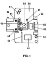
次に図面につき、本発明の実施例を詳しく説明する。
Claims (8)
- 高圧放電ランプのためのランプベースであって、
電子素子(61,62)のための、ランプベース(2)内に配置された取付基板(50)が設けられている形式のものにおいて、
取付基板(50)が、該取付基板(50)に埋め込まれたリング状で金属製のコンタクトエレメント(52)を備えていることを特徴とする、高圧放電ランプのためのランプベース。 - リング状で金属製のコンタクトエレメント(52)の内径が、給電導線(16)の厚さもしくは直径に調和されている、請求項1記載のランプベース。
- リング状で金属製のコンタクトエレメント(52)が、リング開口(53)の領域でホッパ状に形成されている、請求項1記載のランプベース。
- 取付基板(50)が、電気的な絶縁に役立つ開口部(54,55,56)を備えている、請求項1から3までのいずれか1項記載のランプベース。
- 高圧放電ランプであって、
ランプベース(2)と、電子素子(61,62)のための、該ランプベース(2)内に配置された取付基板(50)とが設けられている形式のものにおいて、
取付基板(50)が、該取付基板(50)に埋め込まれたリングディスク状で金属製のコンタクトエレメント(52)を備えていることを特徴とする、高圧放電ランプ。 - 高圧放電ランプの給電導線(16)が、リングディスク状で金属製のコンタクトエレメント(52)のリング開口(53)を通ってガイドされていて、かつリングディスク状で金属製のコンタクトエレメント(52)と導電接続されている、請求項5記載の高圧放電ランプ。
- リングディスク状で金属製のコンタクトエレメント(52)が、リング開口(53)の領域でホッパ状に形成されている、請求項5記載の高圧放電ランプ。
- 取付基板(50)が、電気的な絶縁に役立つ開口部(54,55,56)を備えている、請求項5から7までのいずれか1項記載の高圧放電ランプ。
Applications Claiming Priority (2)
| Application Number | Priority Date | Filing Date | Title |
|---|---|---|---|
| DE10339591A DE10339591A1 (de) | 2003-08-26 | 2003-08-26 | Lampensockel für eine Hockdruckentladungslampe und Hochdruckentladungslampe |
| PCT/DE2004/001786 WO2005022576A2 (de) | 2003-08-26 | 2004-08-09 | Lampensockel für eine hochdruckentladungslampe und hochdruckentladungslampe |
Publications (1)
| Publication Number | Publication Date |
|---|---|
| JP2007503684A true JP2007503684A (ja) | 2007-02-22 |
Family
ID=34202129
Family Applications (1)
| Application Number | Title | Priority Date | Filing Date |
|---|---|---|---|
| JP2006524213A Pending JP2007503684A (ja) | 2003-08-26 | 2004-08-09 | 高圧放電ランプのためのランプベースおよび高圧放電ランプ |
Country Status (9)
| Country | Link |
|---|---|
| EP (1) | EP1658661B1 (ja) |
| JP (1) | JP2007503684A (ja) |
| KR (1) | KR101062077B1 (ja) |
| CN (1) | CN100407514C (ja) |
| AT (1) | ATE412996T1 (ja) |
| DE (2) | DE10339591A1 (ja) |
| ES (1) | ES2313048T3 (ja) |
| TW (1) | TW200510673A (ja) |
| WO (1) | WO2005022576A2 (ja) |
Cited By (1)
| Publication number | Priority date | Publication date | Assignee | Title |
|---|---|---|---|---|
| JP2008541360A (ja) * | 2005-05-09 | 2008-11-20 | パテント−トロイハント−ゲゼルシヤフト フユール エレクトリツシエ グリユーラムペン ミツト ベシユレンクテル ハフツング | ランプベース、及びランプベースを備えた高圧放電ランプ |
Families Citing this family (1)
| Publication number | Priority date | Publication date | Assignee | Title |
|---|---|---|---|---|
| CN100557759C (zh) * | 2007-03-27 | 2009-11-04 | 姚流文 | 高压放电灯 |
Citations (4)
| Publication number | Priority date | Publication date | Assignee | Title |
|---|---|---|---|---|
| JPH10214733A (ja) * | 1997-01-28 | 1998-08-11 | Toyo Denso Co Ltd | 放電灯ユニット |
| JPH118140A (ja) * | 1997-06-16 | 1999-01-12 | Ngk Spark Plug Co Ltd | 高圧トランス |
| JP2001102142A (ja) * | 1999-09-30 | 2001-04-13 | Matsushita Electric Works Ltd | ランプソケット及び放電灯点灯装置 |
| JP2002541619A (ja) * | 1999-03-26 | 2002-12-03 | フォークト エレクトロニック アクチエンゲゼルシャフト | 点弧装置を備えたガス放電ランプソケット |
Family Cites Families (4)
| Publication number | Priority date | Publication date | Assignee | Title |
|---|---|---|---|---|
| US6066921A (en) * | 1995-02-28 | 2000-05-23 | Matsushita Electric Works, Ltd. | Discharge lamp lighting device |
| DE19546797A1 (de) * | 1995-12-14 | 1997-06-19 | Amp Gmbh | Anordnung zur Kontaktierung, insbesondere zur Kontaktierung von Gasentladungslampen |
| DE19831042A1 (de) * | 1998-07-13 | 2000-02-17 | Patent Treuhand Ges Fuer Elektrische Gluehlampen Mbh | Beleuchtungssystem mit einer Hochdruckentladungslampe |
| EP1189314B1 (en) * | 1999-09-30 | 2009-09-09 | Panasonic Electric Works Co., Ltd. | Lamp socket and discharge lamp operating device |
-
2003
- 2003-08-26 DE DE10339591A patent/DE10339591A1/de not_active Withdrawn
-
2004
- 2004-08-09 AT AT04762631T patent/ATE412996T1/de not_active IP Right Cessation
- 2004-08-09 JP JP2006524213A patent/JP2007503684A/ja active Pending
- 2004-08-09 ES ES04762631T patent/ES2313048T3/es not_active Expired - Lifetime
- 2004-08-09 DE DE502004008358T patent/DE502004008358D1/de not_active Expired - Lifetime
- 2004-08-09 EP EP04762631A patent/EP1658661B1/de not_active Expired - Lifetime
- 2004-08-09 CN CN2004800246275A patent/CN100407514C/zh not_active Expired - Fee Related
- 2004-08-09 WO PCT/DE2004/001786 patent/WO2005022576A2/de not_active Ceased
- 2004-08-09 KR KR1020067003629A patent/KR101062077B1/ko not_active Expired - Fee Related
- 2004-08-23 TW TW093125333A patent/TW200510673A/zh unknown
Patent Citations (4)
| Publication number | Priority date | Publication date | Assignee | Title |
|---|---|---|---|---|
| JPH10214733A (ja) * | 1997-01-28 | 1998-08-11 | Toyo Denso Co Ltd | 放電灯ユニット |
| JPH118140A (ja) * | 1997-06-16 | 1999-01-12 | Ngk Spark Plug Co Ltd | 高圧トランス |
| JP2002541619A (ja) * | 1999-03-26 | 2002-12-03 | フォークト エレクトロニック アクチエンゲゼルシャフト | 点弧装置を備えたガス放電ランプソケット |
| JP2001102142A (ja) * | 1999-09-30 | 2001-04-13 | Matsushita Electric Works Ltd | ランプソケット及び放電灯点灯装置 |
Cited By (1)
| Publication number | Priority date | Publication date | Assignee | Title |
|---|---|---|---|---|
| JP2008541360A (ja) * | 2005-05-09 | 2008-11-20 | パテント−トロイハント−ゲゼルシヤフト フユール エレクトリツシエ グリユーラムペン ミツト ベシユレンクテル ハフツング | ランプベース、及びランプベースを備えた高圧放電ランプ |
Also Published As
| Publication number | Publication date |
|---|---|
| DE502004008358D1 (de) | 2008-12-11 |
| KR101062077B1 (ko) | 2011-09-02 |
| CN100407514C (zh) | 2008-07-30 |
| ATE412996T1 (de) | 2008-11-15 |
| DE10339591A1 (de) | 2005-03-24 |
| EP1658661B1 (de) | 2008-10-29 |
| WO2005022576A3 (de) | 2005-09-01 |
| KR20070029615A (ko) | 2007-03-14 |
| WO2005022576A2 (de) | 2005-03-10 |
| CN1842945A (zh) | 2006-10-04 |
| TW200510673A (en) | 2005-03-16 |
| TWI329726B (ja) | 2010-09-01 |
| ES2313048T3 (es) | 2009-03-01 |
| EP1658661A2 (de) | 2006-05-24 |
Similar Documents
| Publication | Publication Date | Title |
|---|---|---|
| US6429591B1 (en) | Lamp socket and discharge lamp operating device | |
| CN100467943C (zh) | 具有变压器的灯座和高压放电灯 | |
| JP2000506673A (ja) | 例えば車両用ヘッドランプ等のガス放電ランプ | |
| JP4915892B2 (ja) | 高圧放電ランプ用のランプ口金および高圧放電ランプ | |
| US6429606B1 (en) | Electronic gas-lighting device | |
| JP2007503684A (ja) | 高圧放電ランプのためのランプベースおよび高圧放電ランプ | |
| JP5841692B2 (ja) | ベース内に接点路を備える放電ランプ | |
| CN100549513C (zh) | 高压放电灯用的灯座和高压放电灯 | |
| JP4709896B2 (ja) | ランプベース、及びランプベースを備えた高圧放電ランプ | |
| CN201222815Y (zh) | 一种紧凑型高强度放电灯触发器及电路板 | |
| CN102612624A (zh) | 高压放电灯 | |
| CN1866638B (zh) | 用于灯的灯座 | |
| CN103975411B (zh) | 高压气体放电灯 | |
| CN101291559B (zh) | 一种紧凑型高强度放电灯触发器及电路板 | |
| JP2007129241A (ja) | 放電灯点灯装置 |
Legal Events
| Date | Code | Title | Description |
|---|---|---|---|
| A621 | Written request for application examination |
Free format text: JAPANESE INTERMEDIATE CODE: A621 Effective date: 20070524 |
|
| A131 | Notification of reasons for refusal |
Free format text: JAPANESE INTERMEDIATE CODE: A131 Effective date: 20090812 |
|
| A601 | Written request for extension of time |
Free format text: JAPANESE INTERMEDIATE CODE: A601 Effective date: 20091002 |
|
| A602 | Written permission of extension of time |
Free format text: JAPANESE INTERMEDIATE CODE: A602 Effective date: 20091009 |
|
| A521 | Request for written amendment filed |
Free format text: JAPANESE INTERMEDIATE CODE: A523 Effective date: 20100201 |
|
| A02 | Decision of refusal |
Free format text: JAPANESE INTERMEDIATE CODE: A02 Effective date: 20100519 |