JP2007507366A - Method for forming a running board with a step board - Google Patents
Method for forming a running board with a step board Download PDFInfo
- Publication number
- JP2007507366A JP2007507366A JP2006529509A JP2006529509A JP2007507366A JP 2007507366 A JP2007507366 A JP 2007507366A JP 2006529509 A JP2006529509 A JP 2006529509A JP 2006529509 A JP2006529509 A JP 2006529509A JP 2007507366 A JP2007507366 A JP 2007507366A
- Authority
- JP
- Japan
- Prior art keywords
- parison
- step plate
- subcavity
- running board
- insert
- Prior art date
- Legal status (The legal status is an assumption and is not a legal conclusion. Google has not performed a legal analysis and makes no representation as to the accuracy of the status listed.)
- Pending
Links
Images





Classifications
-
- B—PERFORMING OPERATIONS; TRANSPORTING
- B29—WORKING OF PLASTICS; WORKING OF SUBSTANCES IN A PLASTIC STATE IN GENERAL
- B29C—SHAPING OR JOINING OF PLASTICS; SHAPING OF MATERIAL IN A PLASTIC STATE, NOT OTHERWISE PROVIDED FOR; AFTER-TREATMENT OF THE SHAPED PRODUCTS, e.g. REPAIRING
- B29C49/00—Blow-moulding, i.e. blowing a preform or parison to a desired shape within a mould; Apparatus therefor
- B29C49/20—Blow-moulding, i.e. blowing a preform or parison to a desired shape within a mould; Apparatus therefor of articles having inserts or reinforcements ; Handling of inserts or reinforcements
-
- B—PERFORMING OPERATIONS; TRANSPORTING
- B29—WORKING OF PLASTICS; WORKING OF SUBSTANCES IN A PLASTIC STATE IN GENERAL
- B29C—SHAPING OR JOINING OF PLASTICS; SHAPING OF MATERIAL IN A PLASTIC STATE, NOT OTHERWISE PROVIDED FOR; AFTER-TREATMENT OF THE SHAPED PRODUCTS, e.g. REPAIRING
- B29C49/00—Blow-moulding, i.e. blowing a preform or parison to a desired shape within a mould; Apparatus therefor
- B29C49/02—Combined blow-moulding and manufacture of the preform or the parison
- B29C49/04—Extrusion blow-moulding
-
- B—PERFORMING OPERATIONS; TRANSPORTING
- B29—WORKING OF PLASTICS; WORKING OF SUBSTANCES IN A PLASTIC STATE IN GENERAL
- B29C—SHAPING OR JOINING OF PLASTICS; SHAPING OF MATERIAL IN A PLASTIC STATE, NOT OTHERWISE PROVIDED FOR; AFTER-TREATMENT OF THE SHAPED PRODUCTS, e.g. REPAIRING
- B29C49/00—Blow-moulding, i.e. blowing a preform or parison to a desired shape within a mould; Apparatus therefor
- B29C49/20—Blow-moulding, i.e. blowing a preform or parison to a desired shape within a mould; Apparatus therefor of articles having inserts or reinforcements ; Handling of inserts or reinforcements
- B29C2049/2017—Blow-moulding, i.e. blowing a preform or parison to a desired shape within a mould; Apparatus therefor of articles having inserts or reinforcements ; Handling of inserts or reinforcements outside the article
-
- B—PERFORMING OPERATIONS; TRANSPORTING
- B29—WORKING OF PLASTICS; WORKING OF SUBSTANCES IN A PLASTIC STATE IN GENERAL
- B29C—SHAPING OR JOINING OF PLASTICS; SHAPING OF MATERIAL IN A PLASTIC STATE, NOT OTHERWISE PROVIDED FOR; AFTER-TREATMENT OF THE SHAPED PRODUCTS, e.g. REPAIRING
- B29C49/00—Blow-moulding, i.e. blowing a preform or parison to a desired shape within a mould; Apparatus therefor
- B29C49/24—Lining or labelling
- B29C2049/2464—Means for verifying or keeping the position of the lining or label, e.g. sensors, or attachment on mould wall
- B29C2049/2472—Means for verifying or keeping the position of the lining or label, e.g. sensors, or attachment on mould wall using vacuum
-
- B—PERFORMING OPERATIONS; TRANSPORTING
- B29—WORKING OF PLASTICS; WORKING OF SUBSTANCES IN A PLASTIC STATE IN GENERAL
- B29C—SHAPING OR JOINING OF PLASTICS; SHAPING OF MATERIAL IN A PLASTIC STATE, NOT OTHERWISE PROVIDED FOR; AFTER-TREATMENT OF THE SHAPED PRODUCTS, e.g. REPAIRING
- B29C49/00—Blow-moulding, i.e. blowing a preform or parison to a desired shape within a mould; Apparatus therefor
- B29C49/42—Component parts, details or accessories; Auxiliary operations
- B29C49/48—Moulds
- B29C49/4802—Moulds with means for locally compressing part(s) of the parison in the main blowing cavity
- B29C2049/4805—Moulds with means for locally compressing part(s) of the parison in the main blowing cavity by closing the mould halves
-
- B—PERFORMING OPERATIONS; TRANSPORTING
- B29—WORKING OF PLASTICS; WORKING OF SUBSTANCES IN A PLASTIC STATE IN GENERAL
- B29C—SHAPING OR JOINING OF PLASTICS; SHAPING OF MATERIAL IN A PLASTIC STATE, NOT OTHERWISE PROVIDED FOR; AFTER-TREATMENT OF THE SHAPED PRODUCTS, e.g. REPAIRING
- B29C49/00—Blow-moulding, i.e. blowing a preform or parison to a desired shape within a mould; Apparatus therefor
- B29C49/42—Component parts, details or accessories; Auxiliary operations
- B29C49/48—Moulds
- B29C49/4802—Moulds with means for locally compressing part(s) of the parison in the main blowing cavity
- B29C49/4812—Moulds with means for locally compressing part(s) of the parison in the main blowing cavity and welding opposite wall parts of the parisons or preforms to each other
-
- B—PERFORMING OPERATIONS; TRANSPORTING
- B29—WORKING OF PLASTICS; WORKING OF SUBSTANCES IN A PLASTIC STATE IN GENERAL
- B29L—INDEXING SCHEME ASSOCIATED WITH SUBCLASS B29C, RELATING TO PARTICULAR ARTICLES
- B29L2031/00—Other particular articles
- B29L2031/30—Vehicles, e.g. ships or aircraft, or body parts thereof
- B29L2031/3005—Body finishings
Landscapes
- Engineering & Computer Science (AREA)
- Manufacturing & Machinery (AREA)
- Mechanical Engineering (AREA)
- Blow-Moulding Or Thermoforming Of Plastics Or The Like (AREA)
- Moulds For Moulding Plastics Or The Like (AREA)
- Vehicle Step Arrangements And Article Storage (AREA)
Abstract
車両に搭載するための成形ランニングボード組立品を製造する方法は、ランニングボードの本体をブロー成形し、ステップ板や装飾片などの追加の部材を1つ以上組み込む各工程を有してなる。この方法は、サブキャビティ内のブロー成形キャビティ中にインサートを配置し、減圧によりインサートを保持し、次いで、パリソンを押し出し、ブロー成形すると同時に、ランニングボードを成形し、インサートを組み込む各工程を含む。 A method of manufacturing a molded running board assembly for mounting on a vehicle includes the steps of blow molding the body of the running board and incorporating one or more additional members such as step plates and decorative pieces. This method includes the steps of placing the insert in a blow molding cavity in the subcavity, holding the insert by vacuum, then extruding and blow molding the parison, simultaneously molding the running board and incorporating the insert.
Description
本発明は、自動車用のランニングボードを製造する方法に関する。本発明は、特に、ステップ板および必要に応じての1つ以上の装飾インサートを含むランニングボードを形成する方法に関する。 The present invention relates to a method of manufacturing a running board for an automobile. In particular, the present invention relates to a method of forming a running board including a step board and optionally one or more decorative inserts.
大型のホイールとタイヤに搭載されたまたは一段と高くされたサスペンション・システムを有する自動車の多くは、車両の床が、車両が走行する路面からかなり高くなっている。そのような車両の多くには、車両に乗り易くするためのステップが設けられている。これらはしばしば、ランニングボードと称される。一般に、ランニングボードは、トラックやスポーツ・ユーティリティー・ビークル(SUV)などに用いられる。ランニングボードは、車両のロッカーパネル区域から外面に突出し、車両の乗り降りを使用とする人の足を支持するのに十分な支持表面区域を与える構造的ステップを提供する。ランニングボードは、ロッカーパネルとは別個の構造体であってもよく、車両の乗り降りのときに、ランニングボードに立つ人の荷重を支持するための構造的支持を必要とする。ランニングボードは、取り付けられたときに、人がランニングボードを用いて、踏む上側支持面を有する。この支持面は、ランニングボードの長手方向に沿って延在するが、比較的狭くてもよい。したがって、人が踏む面は、ステップ・パッドを含むことが望ましい。ステップ・パッドは、人が足に体重をかけたときに、その人の足が支持面から滑らないように役立つ牽引を補助する隆起部分を含んでもよい。このステップ・パッドは、取り付けられたランニングボードに魅力的な外観を与える、隆起・沈下区域、リブなどのパターンを含んでもよい。 Many automobiles with suspension systems mounted on larger wheels and tires or raised higher have the vehicle floor quite high from the road surface on which the vehicle travels. Many of such vehicles are provided with a step for facilitating getting on the vehicle. These are often referred to as running boards. Generally, a running board is used for a track, a sports utility vehicle (SUV), and the like. The running board protrudes outward from the vehicle rocker panel area and provides a structural step that provides sufficient support surface area to support the feet of a person using the vehicle to get on and off. The running board may be a separate structure from the rocker panel and requires structural support to support the load of a person standing on the running board when getting on and off the vehicle. When installed, the running board has an upper support surface that a person steps on using the running board. This support surface extends along the longitudinal direction of the running board, but may be relatively narrow. Therefore, it is desirable that the surface that the person steps on includes a step pad. The step pad may include a raised portion that assists in traction that helps keep the person's foot from slipping off the support surface when the person puts weight on the foot. The step pad may include patterns such as raised and subsidized areas, ribs, etc. that give the attached running board an attractive appearance.
ランニングボードは、車両の前後のホイール間に延在する、よく見える外面を有する。ランニングボードとランニングボードが取り付けられた車両の外観を向上させるために、1つ以上の装飾片を含むことがしばしば望ましい。この装飾片は、ランニングボードの部分に沿って延在していてよい。 The running board has a well visible outer surface that extends between the front and rear wheels of the vehicle. It is often desirable to include one or more decorative pieces to improve the appearance of the running board and the vehicle to which the running board is attached. The decorative piece may extend along a portion of the running board.
ブロー成形法は、中空構造体を持つ商品を製造する非常に費用効率の高い方法であり、ランニングボードなどの、構造強度を必要とする商品を製造するのに使用できる。したがって、そのようなランニングボードを形成するためにブロー成形法を使用することが望ましい。 The blow molding method is a very cost-effective method of producing a product with a hollow structure and can be used to produce a product that requires structural strength, such as a running board. Therefore, it is desirable to use a blow molding method to form such a running board.
外観、構造強度および滑り防止特性の所望の基準の全てを満たすために、ランニングボード組立品は、複数の部品を含んでもよい。これらの部品としては、ランニングボード自体、ステップ・パッドおよび1つ以上の装飾片が挙げられる。 In order to meet all of the desired criteria of appearance, structural strength and anti-slip properties, the running board assembly may include multiple parts. These parts include the running board itself, step pads and one or more decorative pieces.
自動車組立工場に出荷するために自動車部品供給者による製造のためにこれらの構成部材の全てを含む副組立品を形成することが望ましいであろう。ランニングボード副組立品は、自動車組立工場で、車両に取り付けられる。 It would be desirable to form a subassembly that includes all of these components for manufacture by an auto parts supplier for shipment to an automobile assembly plant. The running board subassembly is attached to the vehicle at the automobile assembly plant.
したがって、そのような副組立品のための構成部材を製造し、商業的かつ経済的な方式で副組立品を形成する必要性がある。 Accordingly, there is a need to manufacture components for such subassemblies and form the subassemblies in a commercial and economical manner.
本発明によれば、ランニングボードおよびインサートのランニングボード組立品を製造する方法は、それぞれ成形キャビティを有する補完的成形型部材を提供する工程を有してなる。成形型部材の少なくとも1つは、成形型部材のキャビティ内に少なくとも1つのインサート用サブキャビティを有する。この方法は、インサートを提供する工程を含む。この方法はさらに、インサートをサブキャビティ中に挿入し、サブキャビティを減圧してインサートを適所に保持する各工程を含む。次いで、パリソンを成形型部材の間に押し出す。成形型部材を閉じ、パリソンを成形型部材の閉じたキャビティ内で膨張させて、ランニングボードを成形すると同時に、インサートとランニングボードを一体化して、ランニングボード組立品を製造する。 In accordance with the present invention, a method for manufacturing a running board and an insert running board assembly includes providing complementary mold members each having a molding cavity. At least one of the mold members has at least one insert subcavity within the cavity of the mold member. The method includes providing an insert. The method further includes the steps of inserting the insert into the subcavity and depressurizing the subcavity to hold the insert in place. The parison is then extruded between the mold members. The mold member is closed and the parison is expanded in the closed cavity of the mold member to mold the running board, and at the same time, the insert and the running board are integrated to produce a running board assembly.
本発明のある態様によれば、インサートはステップ板である。 According to one aspect of the invention, the insert is a step plate.
本発明の別の態様によれば、インサートは装飾片である。 According to another aspect of the invention, the insert is a decorative piece.
本発明の特に好ましい実施の形態によれば、ステップ板は、パリソンとの熱結合に適合した成形用滑り防止材料から形成される。本発明のさらに好ましい態様において、本発明の方法は、パリソンが成形用ステップ板と接触して、ステップ板の温度を成形に適した温度まで上昇させるようにパリソンを膨張させる工程を含む。その方法はさらに、パリソンを膨張させて、成形用ステップ板をサブキャビティ内の成形パターンに押し付けて、ステップ板の表面を成形すると同時に、ステップ板を、パリソンから形成されるランニングボードに組み込む工程を含む。 According to a particularly preferred embodiment of the invention, the step plate is formed from a molding anti-slip material adapted for thermal bonding with the parison. In a further preferred embodiment of the present invention, the method of the present invention comprises the step of inflating the parison so that the parison is in contact with the molding step plate and the temperature of the step plate is raised to a temperature suitable for molding. The method further includes the step of inflating the parison and pressing the molding step plate against the molding pattern in the subcavity to mold the surface of the step plate while simultaneously incorporating the step plate into a running board formed from the parison. Including.
本発明のさらに別の態様によれば、ステップ板は、金属材料から形成されていてよく、そのステップ板は、少なくとも1つの鍵形リブを含む。本発明のこの態様の好ましい実施の形態によれば、本発明の方法は、鍵形リブが、成形されたパリソン内に封入されるようにパリソンを金属製ステップ板に対してブロー成形する工程を含む。 According to yet another aspect of the invention, the step plate may be formed from a metallic material, the step plate including at least one key-shaped rib. According to a preferred embodiment of this aspect of the invention, the method of the invention comprises the step of blow molding the parison against a metal step plate such that the key-shaped rib is enclosed within the molded parison. Including.
本発明の別の態様によれば、インサートは、パリソンと熱結合できない装飾片である。本発明のこの態様の好ましい実施の形態において、サブキャビティは、パリソンが膨張した際に、パリソンの一部分がアンダーカット中に流入するように、サブキャビティの周囲の少なくとも一部分の周りにアンダーカットを含む。 According to another aspect of the invention, the insert is a decorative piece that cannot be thermally bonded to the parison. In a preferred embodiment of this aspect of the invention, the subcavity includes an undercut around at least a portion of the circumference of the subcavity such that when the parison is expanded, a portion of the parison flows during the undercut. .
本発明の好ましい実施の形態の以下の説明および以下の図面を参照して、本発明の様々な他の態様と目的が理解されるであろう。 Various other aspects and objectives of the present invention will be understood with reference to the following description of preferred embodiments of the invention and the following drawings.
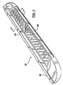
図1は、概して20で表示されたランニングボード組立品を示している。ランニングボード組立品は、ランニングボード22、ステップ・パッド24および装飾片26を有してなる。
FIG. 1 shows a running board assembly, generally designated 20. The running board assembly includes a running
ランニングボード22は上側支持面30を有する。ステップ・パッド24は、本発明の方法にしたがって支持面30に付着される。この方法を、以下により詳しく説明する。ランニングボード22は、ブロー成形法により形成される。図2をよく見ると、ランニングボードは、複数の凹部32を含むのが分かるであろう。これらの凹部は、公知の方式によりブロー成形型内で移動部材により形成される。凹部32は、パリソンの内面を反対の部分と接触させて、複数のリブを形成する。これらのリブによって、必要とされる構造要件を満たすように、ブロー成形されたランニングボードに構造強度が与えられる。ランニングボード22に十分な強度を与えるために、どのようなパターンのリブを形成してもよい。
The running
ここで、本発明の方法を、図4から11を参照して、より詳しく説明する。図4は、ブロー成形型40を示している。ブロー成形型は、第1の成形半型または成形部材42および補完的な成形半型または成形部材44を含む。成形半型42および44は、それぞれ、ラム46および48によって互いに向かったり離れたり移動可能なものとして図示されている。成形半型42および44の各々は、それぞれ、供給導管50および52を有する。供給導管50および52は、必要に応じて、冷却用流体を供給する。さらに、供給導管52は、以下により詳しく説明するように、真空源も含む。
The method of the present invention will now be described in more detail with reference to FIGS. FIG. 4 shows a
成形半型42および44の各々は、成形キャビティを含む。図4において、成形半型44内のキャビティ60のみが見えている。成形キャビティ60は、ランニングボードの一部分の形状を決定し、支持面30の全てではないかもしれないが、相当な部分を成形するのに必要な構造を含む。成形半型44内の成形キャビティ60はサブキャビティ62も含む。サブキャビティ62は、ステップ・パッドの上面となるものの上に所望のパターンを成形するための構造を含む。
Each of the
本発明のこの態様によれば、本発明の方法は、成形用ステップ板70を提供し、パリソン72を押し出す各工程を含む。パリソン72は、公知の押出ヘッドから押し出されたものであってよい。
In accordance with this aspect of the present invention, the method of the present invention includes the steps of providing a forming
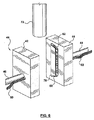
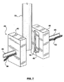
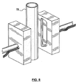
図5は、ステップ板70の成形半型42および44の間の位置への移動を示している。図6は、成形用ステップ板70の、成形半型44のキャビティ60中への移動を示している。図7は、サブキャビティ62内に完全に入ったステップ板70の最終位置を示している。図4,5,6および7に示したようなステップ板70の移動は、プログラム可能なロボット・アームを用いて実施するのが最も容易である。ステップ板70の供給源は、1つ以上のロボット・アームにより掴まれ、取り出される場所に配置されていてよい。ロボット・アームは、成形用ステップ板70を、それがサブキャビティ62内に配置されるまで移動させる。ロボット・アームが成形用ステップ板70をサブキャビティ62内に一旦配置したら、供給導管52から利用できる減圧をサブキャビティ62に適用し、それにより、成形用ステップ板70は、サブキャビティ62内に保持され、精確に位置決めされる。次いで、ロボット・アームは、もはや成形半型42および44の間に位置しないように引っ込められる。この操作が完了したときに、図7および8に示したように、パリソン72が押し出されて、成形半型の間に延在する。図8はパリソンの押出しの完了を示しており、これらの成形半型は今では、パリソンの周りに閉じられる準備ができている。
FIG. 5 shows the movement of the
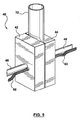
図9は、適切な圧力下でブロー成形用ガスを適用するのに準備ができている、閉じたブロー成形型を形成する成形半型42および44の閉塞を示している。
FIG. 9 shows the closure of
本発明のこの実施の形態において、成形用ステップ板70は、成形半型42内で熱成形される材料であって、パリソン72の材料と相溶性であり、よってこれらの材料が互いに融着して、適切な圧力および温度下で一体構造を形成する材料から製造される。
In this embodiment of the invention, the
サブキャビティ62に適用される減圧は主に、成形用ステップ板70を適所に保持することを意図したものである。成形用ステップ板の温度が、その成形温度に近い温度まで上げられていない場合、真空の力のみの下では、ステップ板70は実質的に成形されない。しかしながら、ブロー成形用ガスがパリソン72の内部に供給されたときに、パリソンは、成形可能な温度であり、パリソンは、成形型40内で膨張させられる。パリソンが膨張するときに、パリソンの一部分が成形用ステップ板70と接触する。これにより、熱がパリソンの壁部から成形用ステップ板70へと伝達される。さらに、パリソン72が膨張し続けるにつれ、パリソンは成形用ステップ板70に相当な圧力を加え、このステップ板をサブキャビティ62内に含まれるパターンに押し付ける。
The reduced pressure applied to the
ブロー成形圧が十分であることが好ましい。ブロー成形圧が約90psi(約620kPa)以上であることが最も好ましい。 It is preferred that the blow molding pressure is sufficient. Most preferably, the blow molding pressure is about 90 psi (about 620 kPa) or higher.
図4に示したような成形用ステップ板70は、成形用プラスチックの比較的薄い細長い一片である。このプラスチック片は、約1から1.5ミリメートル厚であってよい。サブキャビティ62は、プラスチック片の厚さほど深くないことが好ましい。1から1.5ミリメートル厚の細長い一片について、キャビティは、約0.5ミリメートルの深さのものであってよい。このとは、成形が完了した際に、ステップが、成形された支持面30から上方に約0.5ミリメートル以上だけ隆起しており、一方で、ステップ板の残りの部分は、その下にあり、パリソンの壁部中に組み込まれている。これが図2に示されている。
The
ブロー成形圧が解放された後、典型的なブロー成形法では、成形型40は冷却され、開かれる。開かれた成形型が図10に示されている。ここで、ランニングボード組立品20は、ばり取りの準備ができている状態で成形半型から取り出されたものとして示されている。
After the blow molding pressure is released, in a typical blow molding process, the
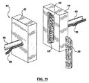
成形されたランニングボード組立品20を取り出した後、このランニングボード組立品を所望のようにばり取りし、成形型から取り外す。これが図11に示されている。
After the molded running
図1に示したランニングボード組立品20は、ステップ・パッド24を含む。ステップ・パッド24は、ブロー成形プロセス中に行われる、ステップ・パッド24とランニングボード22との間の熱融着によって、ランニングボード組立品20に組み込まれる。本発明の代わりの態様によれば、ステップ・パッドは、成形用材料またはランニングボードの材料と熱融着する材料からなっている必要はない。
The running
図12は、ステップ・パッド124を示している。ステップ・パッド124は細長い金属片である。この金属片は、一方の面には隆起パターン125を、他方の面には少なくとも1つ、好ましくは複数の長手方向に延在する鍵形リブ128を含む。
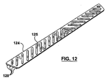
FIG. 12 shows the
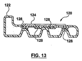
図13は、ランニングボード組立品120を断面で示している。ランニングボード組立品120は、ブロー成形中にランニングボード122に組み込まれたステップ・パッド124を含む。
FIG. 13 shows the running
図12および13に示したランニングボード組立品120を製造する方法は、図4から11に示した方法と似ている。本発明のこの態様によれば、金属製ステップ・パッド124が、成形型140の一方の成形半型144内のサブキャビティ162内に配置される。
The method of manufacturing the running
ステップ・パッド124は、貯蔵場所から得て、コンピュータ制御されたロボット・アームによりサブキャビティ162中に配置してよい。ステップ・パッド124がサブキャビティ162内に一旦配置されたら、次いで、サブキャビティ162に減圧を適用して、このステップ・パッドを適所に保持する。
The
減圧によってステップ・パッドが適所に一旦保持されたら、次いで、パリソン72が成形半型142および144の間に押し出され、成形型が閉じられ、パリソンの内部にブロー成形圧が加えられる。ブロー成形圧下でパリソンが膨張するにつれ、パリソンの壁部の一部分が、複数の鍵形リブ128を含むステップ・パッド124の面に接触する。ステップ・パッド124の隆起部分125は、サブキャビティ162の面を圧迫する。
Once the step pad is held in place by depressurization, the
図13を参照すると、パリソンの壁部がブロー成形圧下でリブ128に押し付けられるにつれ、その壁部の一部分がリブの周りに流れ込むのが観察される。各リブは実質的に鍵形である。これによって、パリソンの壁部内に埋め込まれるリブの部分は、アンダーカットまたは幅の小さい部分を有することを意味する。図13に示した本発明の好ましい実施の形態において、リブはT字形である。成形型が冷却されながらパリソンの壁部が固化するときに、パリソンの壁部の冷却されたプラスチックがリブのアンダーカットまたは薄い領域中に延在し、それによって、ランニングボードが形成されたときに、ステップ・パッド124をランニングボード組立品120中に永久的に組み込む。それゆえ、成形型が開いたときに、排出される部品は、ステップ・パッド124が一体化されたランニングボード組立品120である。
Referring to FIG. 13, as the parison wall is pressed against the
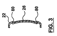
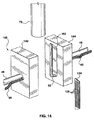
ここで、図1,2,3および15を参照する。図示したように、ランニングボード組立品20は装飾片26を含む。この装飾片は、ランニングボード22が形成されるときにパリソン72と熱融着できる成形用プラスチックであってよい。あるいは、装飾片26は、ランニングボード22と熱融着しない材料から製造してもよい。この点に関して、装飾片26は、ステップ・パッド124と類似の金属片であってよい。
Reference is now made to FIGS. As shown, the running
装飾片26はインサートの形態にある。このインサートは、ステップ板70またはステップ・パッド124と類似の様式で成形半型43内に配置されてよい。これを実施するために、別個のサブキャビティ263がある。サブキャビティ263は、サブキャビティ62と同じ成形半型内、または他の成形半型内のいずれかにある。装飾片26には、ステップ・パッド124のリブ128と類似の保持手段を使用してもよいが、代わりの保持システムが、図3および15の拡大図に示されている。
The
装飾片26が中に配置され、減圧に維持されるサブキャビティ263は、サブキャビティ263の周辺の周りに延在するアンダーカット264を含むことが都合よい。ステップ・パッド24またはステップ・パッド124、および1つ以上の装飾片26の両方を含むランニングボード組立品は、図4から11に関して説明した方法を用いて形成してもよい。パリソンの壁部が装飾片26に向かって膨張させられるにつれ、パリソンからの材料が装飾片26の面に対して押し付けられる。ブロー成形圧下では、パリソンの材料の小さな部分80がアンダーカット中に押し込められる。その結果、パリソンのその部分が装飾片26の他方の面に隣接している。成形プロセスが完了した際に、装飾片26がランニングボード組立品20中に永久的に保持されるように、装飾片26を収容するサブキャビティの周囲に沿って十分な長さのアンダーカットが提供される。実際に、パリソンの材料の部分80が装飾片26の周囲の縁の実質的に全ての周りに流動するように、アンダーカットがサブキャビティの実質的に周囲に亘って延在することが最も好ましい。これによって、実際に、装飾片26が永久的に額縁様式で保持される。
Conveniently, the
装飾片26は、パリソンの冷却された材料によって保持される。それゆえ、装飾片26は、任意の所望の材料から製造されてもよい。その材料としては、ランニングボード22の材料と相溶性ではない金属またはプラスチックや、ランニングボード22の材料と相溶性である材料が挙げられる。
The
上述したように説明してきたが、本発明の好ましい実施の形態には、様々な態様がある。先の説明は説明としてのみ捉えるべきであり、本発明の完全な範囲は、添付の特許請求の範囲を参照して判断すべきである。 As described above, the preferred embodiment of the present invention has various aspects. The foregoing description should be taken as illustrative only, and the full scope of the present invention should be determined with reference to the appended claims.
20,120 ランニングボード組立品
22 ランニングボード
24,124 ステップ・パッド
26 装飾片
30 支持面
32 凹部
40 ブロー成形型
42,44 成形半型
50,52 供給導管
60 成形キャビティ
62,162,263 サブキャビティ
70 ステップ板
72 パリソン
20, 120
Claims (17)
それぞれ成形キャビティを有する補完的成形部材であって、少なくとも一方が、当該成形部材のキャビティ内に少なくとも1つのサブキャビティを有する成形部材を提供し、
インサートを提供し、
該インサートを前記サブキャビティ内に挿入し、
該サブキャビティに減圧を適用して、前記インサートを適所に保持し、
前記成形部材の間にパリソンを押し出し、
前記成形部材を閉じ、
前記キャビティ内で前記パリソンを膨張させて、前記ランニングボートを成形すると同時に、前記インサートおよび該ランニングボードを一体化させる、
各工程を有してなる方法。 In a method of manufacturing a running board and an insert running board assembly,
Providing complementary molded members each having a molded cavity, at least one of which has at least one subcavity within the cavity of the molded member;
Providing inserts,
Inserting the insert into the subcavity;
Applying a vacuum to the subcavity to hold the insert in place;
Extrude the parison between the molded members,
Closing the molded member,
Inflating the parison in the cavity to mold the running boat and simultaneously integrate the insert and the running board;
A method comprising each step.
Applications Claiming Priority (2)
| Application Number | Priority Date | Filing Date | Title |
|---|---|---|---|
| US10/673,316 US7332120B2 (en) | 2003-09-30 | 2003-09-30 | Method for molding running board with step plate |
| PCT/CA2004/001645 WO2005030469A1 (en) | 2003-09-30 | 2004-09-08 | Method for molding running board with step plate |
Publications (1)
| Publication Number | Publication Date |
|---|---|
| JP2007507366A true JP2007507366A (en) | 2007-03-29 |
Family
ID=34376585
Family Applications (1)
| Application Number | Title | Priority Date | Filing Date |
|---|---|---|---|
| JP2006529509A Pending JP2007507366A (en) | 2003-09-30 | 2004-09-08 | Method for forming a running board with a step board |
Country Status (6)
| Country | Link |
|---|---|
| US (1) | US7332120B2 (en) |
| EP (1) | EP1667835A4 (en) |
| JP (1) | JP2007507366A (en) |
| BR (1) | BRPI0414829A (en) |
| CA (1) | CA2535831A1 (en) |
| WO (1) | WO2005030469A1 (en) |
Families Citing this family (27)
| Publication number | Priority date | Publication date | Assignee | Title |
|---|---|---|---|---|
| US8879856B2 (en) | 2005-09-27 | 2014-11-04 | Qualcomm Incorporated | Content driven transcoder that orchestrates multimedia transcoding using content information |
| WO2007147236A1 (en) | 2006-06-21 | 2007-12-27 | Salflex Polymers Ltd. | Running board for vehicle |
| USD596098S1 (en) * | 2009-01-20 | 2009-07-14 | Li-Yue Huang-Tsai | Running board |
| USD596097S1 (en) * | 2009-01-20 | 2009-07-14 | Li-Yue Huang-Tsai | Running board |
| TWM397891U (en) * | 2010-07-01 | 2011-02-11 | wei-jun Qiu | Surface layer structure of a hollow air-blow molding box |
| CZ201143A3 (en) * | 2011-01-27 | 2012-09-26 | Barum Continental Spol. S R. O. | Device for casting gypsum core segment of tire mold and process for producing thereof |
| US20140099454A1 (en) * | 2011-06-07 | 2014-04-10 | Salflex Polymers Limited | Hollow Article With Internal Structural Members |
| US9493646B2 (en) | 2012-04-13 | 2016-11-15 | Ticona Llc | Blow molded thermoplastic composition |
| US9676338B2 (en) * | 2012-05-31 | 2017-06-13 | Metelix Products Inc. | Reinforced blow moulded vehicle running board and method of making same |
| US20140265055A1 (en) * | 2013-03-16 | 2014-09-18 | Chien-Min Hsiao | Hollow box with identification member and device for making the same |
| USD842791S1 (en) * | 2015-06-30 | 2019-03-12 | Winbo-Dongjian Automotive Technology Co., Ltd. | Shark running board |
| USD807804S1 (en) * | 2016-01-12 | 2018-01-16 | Winbo-Dongjian Auto Accessories Manufacturing Co., Ltd. | Auto running board |
| US9707898B1 (en) * | 2016-07-11 | 2017-07-18 | Ford Global Technologies, Llc | Extruded multi-layer molded running board |
| USD805986S1 (en) * | 2016-10-04 | 2017-12-26 | Razer Auto, Inc. | Running board for vehicle |
| US10202011B2 (en) * | 2016-10-26 | 2019-02-12 | Macneil Ip Llc | Two shot injection molded vehicle hitch step |
| USD840309S1 (en) * | 2016-12-07 | 2019-02-12 | Winbo-Dongjian Automotive Technology Co., Ltd. | Running board |
| USD839810S1 (en) * | 2017-03-29 | 2019-02-05 | Shu-Ling Chen | Step for a truck |
| USD875014S1 (en) * | 2017-03-29 | 2020-02-11 | Shu-Ling Chen | Step for a truck |
| US10604076B2 (en) | 2018-01-25 | 2020-03-31 | Westin Automotive Products, Inc. | Running board for vehicles |
| USD867252S1 (en) * | 2018-01-25 | 2019-11-19 | Westin Automotive Products, Inc. | Running board for vehicles |
| USD868661S1 (en) * | 2018-09-27 | 2019-12-03 | M2 Distribution Ltd. | Running board |
| US10518727B1 (en) * | 2018-09-28 | 2019-12-31 | GM Global Technology Operations LLC | Step assembly for energy absorption |
| US10464491B1 (en) | 2018-10-09 | 2019-11-05 | Macneil Ip Llc | Trailer hitch step assembly |
| US11541815B2 (en) * | 2019-05-17 | 2023-01-03 | Vintech Industries, Inc. | Hybrid running board |
| USD954625S1 (en) * | 2019-11-04 | 2022-06-14 | Winbo-Dongjian Automotive Technology Co., Ltd. | Running board |
| US11975687B2 (en) * | 2021-05-19 | 2024-05-07 | Ford Global Technologies, Llc | Vehicle running board and running board manufacturing method |
| USD1076744S1 (en) * | 2025-01-16 | 2025-05-27 | Xiamen Liaojicheng E-commerce Co., Ltd. | Car bumper protector |
Citations (10)
| Publication number | Priority date | Publication date | Assignee | Title |
|---|---|---|---|---|
| JPS52128668U (en) * | 1976-03-29 | 1977-09-30 | ||
| JPS52121663A (en) * | 1976-04-07 | 1977-10-13 | Nippon Petrochemicals Co Ltd | Method of producing antiskid thermoplastic resin molded article |
| JPS61148019A (en) * | 1984-12-21 | 1986-07-05 | Kyoraku Co Ltd | Plastic hollow body by bow molding |
| JPS61246036A (en) * | 1985-04-24 | 1986-11-01 | Kyoraku Co Ltd | Manufacture of plastic hollow body |
| JPS6456524A (en) * | 1987-08-28 | 1989-03-03 | Excel Corp | Pressure-resistant hollow molded product and its manufacture |
| JPH07125056A (en) * | 1993-11-05 | 1995-05-16 | Futaba Kagaku:Kk | In-mold molded product and molding thereof |
| JPH08268057A (en) * | 1995-03-28 | 1996-10-15 | Hayashi Gijutsu Kenkyusho:Kk | Method for molding sun visor with mirror and sun visor |
| JP2002512144A (en) * | 1998-04-21 | 2002-04-23 | エアロクイップ コーポレーション | Car running board |
| JP2002192605A (en) * | 2000-12-25 | 2002-07-10 | Dainippon Printing Co Ltd | Blow molding simultaneous decoration method |
| JP2003251684A (en) * | 2002-02-28 | 2003-09-09 | Kyoraku Co Ltd | Blow molding method for resin hollow molded products |
Family Cites Families (14)
| Publication number | Priority date | Publication date | Assignee | Title |
|---|---|---|---|---|
| DE2210693A1 (en) * | 1972-03-06 | 1973-09-13 | Daimler Benz Ag | Blown plastics container - for fastening in or on metal fuel container, for equalisation |
| US4246734A (en) * | 1978-10-18 | 1981-01-27 | K & M Plastics Inc. | Fold down multi-purpose vehicle seat back core with inmolded metal reenforcing member |
| DE3314682A1 (en) * | 1983-04-22 | 1984-10-25 | Gebr. Happich Gmbh, 5600 Wuppertal | PROFILE BAR, IN PARTICULAR FOR VEHICLES, AND METHOD FOR PRODUCING THE SAME AND DEVICE FOR CARRYING OUT THE METHOD |
| JPS60234823A (en) * | 1984-05-08 | 1985-11-21 | Ishikawajima Harima Heavy Ind Co Ltd | Method for mounting internal insert in blow molding |
| US4664958A (en) * | 1985-10-18 | 1987-05-12 | Owens-Illinois, Inc. | Hollow plastic container having an insert |
| JPH0628897B2 (en) * | 1986-06-30 | 1994-04-20 | 東燃化学株式会社 | Method for manufacturing automobile bumper |
| JPS63159031A (en) * | 1986-12-24 | 1988-07-01 | Ikeda Bussan Co Ltd | Manufacture of internal trim parts |
| US4877147A (en) * | 1988-08-01 | 1989-10-31 | Ford Motor Company | Tank comprising embedded flanged conduit |
| WO1995013938A1 (en) | 1993-11-19 | 1995-05-26 | Cambridge Industries, Inc. | Blow molded structural interior automotive parts |
| US5658027A (en) * | 1995-10-03 | 1997-08-19 | Ford Global Tech Inc | Blow molded vehicle bumper system in method |
| EP0791450A1 (en) * | 1996-02-23 | 1997-08-27 | Lear Corporation | Method and apparatus for joining carpet and plastic |
| US6536844B2 (en) * | 1999-11-18 | 2003-03-25 | Moeller Marine Products | Blow-molded seat assembly and method of making same |
| JP2003236920A (en) | 2002-02-13 | 2003-08-26 | Yazaki:Kk | Method of welding insert parts to blow molding |
| US6688680B1 (en) * | 2002-12-17 | 2004-02-10 | Bayer Polymers Llc | Molded cross vehicle beam |
-
2003
- 2003-09-30 US US10/673,316 patent/US7332120B2/en not_active Expired - Lifetime
-
2004
- 2004-09-08 CA CA002535831A patent/CA2535831A1/en not_active Abandoned
- 2004-09-08 WO PCT/CA2004/001645 patent/WO2005030469A1/en not_active Ceased
- 2004-09-08 BR BRPI0414829-0A patent/BRPI0414829A/en not_active Application Discontinuation
- 2004-09-08 JP JP2006529509A patent/JP2007507366A/en active Pending
- 2004-09-08 EP EP04761808A patent/EP1667835A4/en not_active Withdrawn
Patent Citations (10)
| Publication number | Priority date | Publication date | Assignee | Title |
|---|---|---|---|---|
| JPS52128668U (en) * | 1976-03-29 | 1977-09-30 | ||
| JPS52121663A (en) * | 1976-04-07 | 1977-10-13 | Nippon Petrochemicals Co Ltd | Method of producing antiskid thermoplastic resin molded article |
| JPS61148019A (en) * | 1984-12-21 | 1986-07-05 | Kyoraku Co Ltd | Plastic hollow body by bow molding |
| JPS61246036A (en) * | 1985-04-24 | 1986-11-01 | Kyoraku Co Ltd | Manufacture of plastic hollow body |
| JPS6456524A (en) * | 1987-08-28 | 1989-03-03 | Excel Corp | Pressure-resistant hollow molded product and its manufacture |
| JPH07125056A (en) * | 1993-11-05 | 1995-05-16 | Futaba Kagaku:Kk | In-mold molded product and molding thereof |
| JPH08268057A (en) * | 1995-03-28 | 1996-10-15 | Hayashi Gijutsu Kenkyusho:Kk | Method for molding sun visor with mirror and sun visor |
| JP2002512144A (en) * | 1998-04-21 | 2002-04-23 | エアロクイップ コーポレーション | Car running board |
| JP2002192605A (en) * | 2000-12-25 | 2002-07-10 | Dainippon Printing Co Ltd | Blow molding simultaneous decoration method |
| JP2003251684A (en) * | 2002-02-28 | 2003-09-09 | Kyoraku Co Ltd | Blow molding method for resin hollow molded products |
Also Published As
| Publication number | Publication date |
|---|---|
| BRPI0414829A (en) | 2006-11-14 |
| WO2005030469A1 (en) | 2005-04-07 |
| EP1667835A1 (en) | 2006-06-14 |
| US20050067741A1 (en) | 2005-03-31 |
| EP1667835A4 (en) | 2009-05-13 |
| US7332120B2 (en) | 2008-02-19 |
| CA2535831A1 (en) | 2005-04-07 |
Similar Documents
| Publication | Publication Date | Title |
|---|---|---|
| US7332120B2 (en) | Method for molding running board with step plate | |
| JP4819674B2 (en) | Interior panel for vehicle and method for manufacturing the same | |
| US5122320A (en) | Process for producing a multilayer article | |
| KR960017225A (en) | Automotive interior parts and manufacturing method | |
| CN101203404A (en) | Method for manufacturing an interior trim part comprising a determined surface and/or a determined color profile and article obtained thereby | |
| KR20010031760A (en) | Molded polyolefin and polyphenyloxide products and method for production | |
| US20010000736A1 (en) | Decorative component, process of manufacturing a decorative component, and process of using a decorative component as a piece of internal trim of a vehicle | |
| PT821643E (en) | PROCESS FOR FORMING ARTICLES WITH CONTROLLED THICKNESS LAYERS | |
| EP0702621B1 (en) | Apparatus for producing a thermoplastic article having an undercut cross section | |
| JP2005125736A (en) | Interior with foam layer | |
| JP2000218684A (en) | Blow molding method for resin hollow molded products | |
| JP3444409B2 (en) | Method for producing blow-molded article having decorative layer and blow-molding mold | |
| JP2932454B2 (en) | Composite molded article and method for producing the same | |
| JP2004074660A (en) | Hinge structure of blow molded product with skin | |
| KR100538157B1 (en) | The method for manufacturing and apparatus for catapulting and molding insert cloth | |
| US5207969A (en) | Process of producing blow molded article | |
| JP2005047161A (en) | Decorative molded product and its manufacturing method | |
| JP3839135B2 (en) | Resin molded body, method for manufacturing the same, and manufacturing apparatus therefor | |
| JP3448914B2 (en) | Manufacturing method of assist grip | |
| CN113520123A (en) | Anti-skid cup mat with hard material coated by elastomer material and manufacturing method thereof | |
| JP3693790B2 (en) | Manufacturing method of resin molded body and manufacturing apparatus therefor | |
| JP3917477B2 (en) | Method for producing plastic molded body having skin material and mold used for the method | |
| TWM397891U (en) | Surface layer structure of a hollow air-blow molding box | |
| JP2003245934A5 (en) | ||
| US20080224342A1 (en) | Method For Forming Two-Tone Parts For Automotive Interior Applications |
Legal Events
| Date | Code | Title | Description |
|---|---|---|---|
| A621 | Written request for application examination |
Free format text: JAPANESE INTERMEDIATE CODE: A621 Effective date: 20070904 |
|
| A977 | Report on retrieval |
Free format text: JAPANESE INTERMEDIATE CODE: A971007 Effective date: 20100225 |
|
| A131 | Notification of reasons for refusal |
Free format text: JAPANESE INTERMEDIATE CODE: A131 Effective date: 20100302 |
|
| A601 | Written request for extension of time |
Free format text: JAPANESE INTERMEDIATE CODE: A601 Effective date: 20100602 |
|
| A602 | Written permission of extension of time |
Free format text: JAPANESE INTERMEDIATE CODE: A602 Effective date: 20100609 |
|
| A02 | Decision of refusal |
Free format text: JAPANESE INTERMEDIATE CODE: A02 Effective date: 20110201 |