JP2008024142A - Braking force control device - Google Patents
Braking force control device Download PDFInfo
- Publication number
- JP2008024142A JP2008024142A JP2006198524A JP2006198524A JP2008024142A JP 2008024142 A JP2008024142 A JP 2008024142A JP 2006198524 A JP2006198524 A JP 2006198524A JP 2006198524 A JP2006198524 A JP 2006198524A JP 2008024142 A JP2008024142 A JP 2008024142A
- Authority
- JP
- Japan
- Prior art keywords
- braking force
- speed
- vehicle
- pitching
- master cylinder
- Prior art date
- Legal status (The legal status is an assumption and is not a legal conclusion. Google has not performed a legal analysis and makes no representation as to the accuracy of the status listed.)
- Pending
Links
Images
Landscapes
- Regulating Braking Force (AREA)
Abstract
【課題】制動時のピッチングを制動力制御によって効果的に抑制する制動力制御装置を提供することを課題とする。
【解決手段】運転者による制動操作に基づいて車両に作用する制動力を制御する制動力制御装置1であって、制動力の増加速度を求める制動力増加速度手段3,5を備え、制動力増加速度手段3,5で求めた制動力増加速度が車両のピッチング方向の共振周波数に基づいて設定される所定増加速度範囲内になった場合に制動力増加速度が所定増加速度範囲外になるように制動力を制御することを特徴とする。
【選択図】図1An object of the present invention is to provide a braking force control device that effectively suppresses pitching during braking by braking force control.
A braking force control apparatus (1) for controlling a braking force acting on a vehicle based on a braking operation by a driver, comprising braking force increasing speed means (3, 5) for determining an increasing speed of the braking force. When the braking force increasing speed obtained by the increasing speed means 3 and 5 is within a predetermined increasing speed range set based on the resonance frequency in the pitching direction of the vehicle, the braking force increasing speed is out of the predetermined increasing speed range. And controlling the braking force.
[Selection] Figure 1
Description
本発明は、運転者による制動操作に基づいて車両に作用する制動力を制御する制動力制御装置に関する。 The present invention relates to a braking force control device that controls a braking force acting on a vehicle based on a braking operation by a driver.
運転者によるブレーキ操作により車両を急制動したときには、車両ではフロント側に荷重移動が起こり、フロント側が沈むとともにリヤ側が上がる大きなピッチングが発生する場合がある。このような場合、車両の乗員は、不快感を受け、乗心地が低下する。そこで、このようなピッチングを抑制するための様々な方法が提案されている。特許文献1に記載の制動力制御装置では、車両の減速度に基づいて推定されたピッチ角速度(ピッチング状態量)に応じて前輪の制動力を低下させることにより、ピッチングを抑制している。特に、この制動力制御装置では、ピッチング状態量が大きい場合には小さい場合に比べて前輪の制動力の低下量を多くしている。
タイヤと路面間の摩擦係数は、車速が低くなるほど高くなり、車両が止まる寸前が最も高くなる。そのため、ウォーキング速度(極低速)で走行中に急制動したときには、車両に非常に大きな制動加速度が発生し、車両の減速度が大きくなる。この大きな減速度により、車両のピッチ角が非常に大きくなり、過大なピッチングとなる。このような過大なピッチングが発生した場合には、上記した制動力制御装置のように前輪の制動力を低下させるだけではその過大なピッチングを抑制する効果が十分に得られない。 The coefficient of friction between the tire and the road surface increases as the vehicle speed decreases, and is highest immediately before the vehicle stops. Therefore, when the vehicle is suddenly braked while running at a walking speed (very low speed), a very large braking acceleration is generated in the vehicle, and the deceleration of the vehicle increases. Due to this large deceleration, the pitch angle of the vehicle becomes very large, resulting in excessive pitching. When such an excessive pitching occurs, the effect of suppressing the excessive pitching cannot be sufficiently obtained only by reducing the braking force of the front wheels as in the above-described braking force control device.
そこで、本発明は、制動時のピッチングを制動力制御によって効果的に抑制する制動力制御装置を提供することを課題とする。 Then, this invention makes it a subject to provide the braking force control apparatus which suppresses the pitching at the time of braking effectively by braking force control.
本発明に係る制動力制御装置は、運転者による制動操作に基づいて車両に作用する制動力を制御する制動力制御装置であって、制動力の増加速度を求める制動力増加速度手段を備え、制動力増加速度手段で求めた制動力増加速度が車両のピッチング方向の共振周波数に基づいて設定される所定増加速度範囲内になった場合に制動力増加速度が所定増加速度範囲外になるように制動力を制御することを特徴とする。 A braking force control device according to the present invention is a braking force control device that controls a braking force that acts on a vehicle based on a braking operation by a driver, and includes a braking force increase speed unit that determines an increase rate of the braking force, When the braking force increasing speed obtained by the braking force increasing speed means falls within a predetermined increasing speed range set based on the resonance frequency in the pitching direction of the vehicle, the braking force increasing speed is out of the predetermined increasing speed range. The braking force is controlled.
この制動力制御装置では、制動力増加速度手段により、制動力の増加速度を求める。車両の前後軸方向の制動力によって発生する減速度(制動力増加速度)が車両のピッチング方向の共振周波数と一致すると、車両の前後軸方向の荷重が変動し、さらに、車両のピッチングがオーバシュートし、車両に過大なピッチングが発生する。ピッチング方向の共振周波数は車両によって決まっているので、過大なピッチングが発生する可能性のある制動力増加速度(減速度)の範囲を車両ピッチング共振周波数に基づいて設定することができる。そこで、制動力制御装置では、制動力増加速度が過大なピッチングを発生する可能性のある所定の増加速度範囲内になった場合(つまり、ピッチング共振周波数になった場合)、制動力増加速度が所定の増加速度範囲外になるように制動力を制御する。制動力増加速度がその所定の増加速度範囲外になると、車両のピッチング方向の共振が抑制あるいは発生しなくなり、制動時のピッチングを効果的に抑制することができる。これによって、車両の乗員は過大なピッチングによる不快感を受けなくなり、乗心地が向上する。 In this braking force control device, the braking force increasing speed means obtains the braking force increasing speed. When the deceleration (braking force increasing speed) generated by the braking force in the longitudinal direction of the vehicle coincides with the resonance frequency in the pitching direction of the vehicle, the load in the longitudinal direction of the vehicle fluctuates and the pitching of the vehicle overshoots. In addition, excessive pitching occurs in the vehicle. Since the resonance frequency in the pitching direction is determined by the vehicle, the range of the braking force increase speed (deceleration) in which excessive pitching may occur can be set based on the vehicle pitching resonance frequency. Therefore, in the braking force control device, when the braking force increasing speed is within a predetermined increasing speed range in which excessive pitching may occur (that is, when the pitching resonance frequency is reached), the braking force increasing speed is increased. The braking force is controlled so as to be out of the predetermined increase speed range. When the braking force increase speed is outside the predetermined increase speed range, resonance in the pitching direction of the vehicle is not suppressed or generated, and pitching during braking can be effectively suppressed. As a result, the vehicle occupant is not subject to discomfort due to excessive pitching, and the riding comfort is improved.
なお、制動力増加速度は、運転者による操作が入力されるブレーキペダルから制動力を出力する車輪までの制動系における様々なパラメータの増加速度であり、制動力によって車両に発生する車両の減速度も含むものとする。制動力増加速度手段は、センサによって制動力増加速度(減速度)を直接検出する手段でもよいし、あるいは、センサによって制動力に関する値(例えば、マスタシリンダの油圧、ブレーキペダルの踏力、ブレーキペダルのストローク)を検出し、その検出値から演算によって制動力増加速度を求める手段でもよい。 The braking force increasing speed is an increasing speed of various parameters in the braking system from the brake pedal to which the operation by the driver is input to the wheel that outputs the braking force, and the deceleration of the vehicle generated in the vehicle by the braking force. Shall also be included. The braking force increase speed means may be a means for directly detecting the braking force increase speed (deceleration) by a sensor, or a value related to the braking force (for example, master cylinder hydraulic pressure, brake pedal depression force, brake pedal Stroke) may be detected, and the braking force increase speed may be obtained by calculation from the detected value.
本発明の上記制動力制御装置では、制動力増加速度が所定増加速度範囲内になった場合に制動力増加速度が大きくなるように制動力を制御する構成としてもよい。 The braking force control apparatus according to the present invention may be configured to control the braking force so that the braking force increase speed increases when the braking force increase speed falls within a predetermined increase speed range.
この制動力制御装置では、制動力増加速度が所定の増加速度範囲内になった場合、制動力増加速度を大きくして所定の増加速度範囲外になるように制動力を制御する。このように、制動力増加速度を大きくするために制動力を増加した場合、運転者のブレーキ操作に対して大きな制動力(ひいては、減速度)を確保しつつ、ピッチングを効果的に抑制することができる。 In this braking force control apparatus, when the braking force increase speed falls within a predetermined increase speed range, the braking force is controlled so that the braking force increase speed is increased to be outside the predetermined increase speed range. In this way, when the braking force is increased to increase the braking force increase speed, the pitching is effectively suppressed while ensuring a large braking force (and hence deceleration) for the driver's braking operation. Can do.
本発明の上記制動力制御装置では、制動力増加速度が所定増加速度範囲内になった場合に制動力増加速度が小さくなるように制動力を制御する構成としてもよい。 The braking force control apparatus of the present invention may be configured to control the braking force so that the braking force increase rate becomes smaller when the braking force increase rate falls within a predetermined increase rate range.
この制動力制御装置では、制動力増加速度が所定の増加速度範囲内になった場合、制動力増加速度を小さくして所定の増加速度範囲外になるように制動力を制御する。このように、制動力増加速度を小さくするために制動力を減少した場合でも、ピッチングを効果的に抑制することができる。 In this braking force control device, when the braking force increase speed falls within a predetermined increase speed range, the braking force is controlled so that the braking force increase speed is reduced to be out of the predetermined increase speed range. Thus, even when the braking force is decreased in order to reduce the braking force increase speed, the pitching can be effectively suppressed.
本発明の上記制動力制御装置では、車速を検出する車速検出手段を備え、車速検出手段で検出した車速が所定車速以下の場合に制動力増加速度が所定増加速度範囲外になるように制動力を制御する構成としてもよい。 The braking force control device of the present invention includes vehicle speed detection means for detecting the vehicle speed, and the braking force is increased so that the braking force increase speed is out of the predetermined increase speed range when the vehicle speed detected by the vehicle speed detection means is equal to or lower than the predetermined vehicle speed. It is good also as a structure which controls.
この制動力制御装置では、車速検出手段により、車速を検出する。そして、制動力制御装置では、車速が所定車速以下かつ制動力増加速度が所定の増加速度範囲内になった場合、制動力増加速度が所定の増加速度範囲外になるように制動力を制御する。タイヤと路面間の摩擦係数は車速が低くなるほど高くなるので、低速走行中に制動したときには車両に非常に大きな減速度が発生し、過大なピッチングとなる。つまり、低速ほど、大きなピッチングが発生する可能性がある。所定車速は、タイヤと路面との摩擦係数と車速との関係などを考慮して設定され、制動中に大きなピッチングが発生する可能性がある低速域を判定するための車速閾値である。したがって、この制動力制御装置では、大きなピッチングが発生する可能性がある低速のみで制動力制御を行うので、不要な場面でピッチングを抑制するための制動力制御を行わない。 In this braking force control device, the vehicle speed is detected by the vehicle speed detection means. The braking force control device controls the braking force so that the braking force increase speed is out of the predetermined increase speed range when the vehicle speed is equal to or lower than the predetermined vehicle speed and the braking force increase speed is within the predetermined increase speed range. . Since the coefficient of friction between the tire and the road surface increases as the vehicle speed decreases, a very large deceleration occurs in the vehicle when braking during low-speed traveling, resulting in excessive pitching. That is, there is a possibility that a larger pitching occurs at a lower speed. The predetermined vehicle speed is set in consideration of the relationship between the friction coefficient between the tire and the road surface and the vehicle speed, and is a vehicle speed threshold value for determining a low speed range in which a large pitching may occur during braking. Therefore, in this braking force control device, the braking force control is performed only at a low speed at which a large pitching may occur. Therefore, the braking force control for suppressing the pitching is not performed in an unnecessary scene.
本発明は、制動力増加速度が車両のピッチング方向の共振周波数と一致しないように制動力制御を行うことにより、制動時のピッチングを効果的に抑制することができる。 The present invention can effectively suppress pitching during braking by controlling the braking force so that the braking force increase speed does not coincide with the resonance frequency in the pitching direction of the vehicle.
以下、図面を参照して、本発明に係る制動力制御装置の実施の形態を説明する。 Embodiments of a braking force control device according to the present invention will be described below with reference to the drawings.
本実施の形態では、本発明に係る制動力制御装置を、運転者のブレーキ操作に対して制動力(ブレーキ油圧)を任意に制御することができる制動力制御装置に適用する。本発明に係る制動力制御装置は、ブレーキアクチュエータによって各輪のホイールシリンダの油圧を制御することによって制動力を変化させる。本実施の形態には、ピッチングを抑制するための油圧制御(制動力制御)の違いにより2つの実施の形態があり、第1の実施の形態が加圧制御によってピッチングを抑制する形態であり、第2の実施の形態が減圧制御によってピッチングを抑制する形態である。なお、制動力制御装置は、車両挙動安定化などのシステムの一部として組み込まれる装置でもよいし、あるいは、装置単体でもよい。 In the present embodiment, the braking force control device according to the present invention is applied to a braking force control device that can arbitrarily control a braking force (brake hydraulic pressure) with respect to a driver's braking operation. The braking force control apparatus according to the present invention changes the braking force by controlling the hydraulic pressure of the wheel cylinder of each wheel by a brake actuator. In this embodiment, there are two embodiments due to the difference in hydraulic control (braking force control) for suppressing pitching, and the first embodiment is a mode for suppressing pitching by pressurization control, The second embodiment is a mode in which pitching is suppressed by pressure reduction control. Note that the braking force control device may be a device incorporated as a part of a system such as vehicle behavior stabilization, or may be a single device.
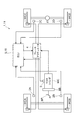
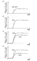
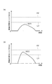
図1〜図3を参照して、第1の実施の形態に係る制動力制御装置1について説明する。図1は、本実施の形態に係る制動力制御装置の構成図である。図2は、マスタシリンダ圧、ホイールシリンダ圧の時間変化を示すグラフであり、(a)が昇圧速度が車両ピッチング共振周波数に相当する昇圧速度範囲より低い場合(通常制動の場合)であり、(b)が昇圧速度が車両ピッチング共振周波数に相当する昇圧速度範囲内の場合(急制動の場合)であり、(c)が昇圧速度が車両ピッチング共振周波数に相当する昇圧速度範囲内のときに加圧制御を行った場合であり、(d)が昇圧速度が車両ピッチング共振周波数に相当する昇圧速度範囲内のときに減圧制御を行った場合である。図3は、マスタシリンダの昇圧速度の時間変化を示すグラフであり、(a)が昇圧速度が車両ピッチング共振周波数に相当する昇圧速度範囲より低い場合(通常制動の場合)であり、(b)が昇圧速度が車両ピッチング共振周波数に相当する昇圧速度範囲内の場合(急制動の場合)である。 With reference to FIGS. 1-3, the braking force control apparatus 1 which concerns on 1st Embodiment is demonstrated. FIG. 1 is a configuration diagram of a braking force control apparatus according to the present embodiment. FIG. 2 is a graph showing temporal changes in the master cylinder pressure and the wheel cylinder pressure, where (a) is a case where the boosting speed is lower than the boosting speed range corresponding to the vehicle pitching resonance frequency (in the case of normal braking). b) is the case where the boosting speed is within the boosting speed range corresponding to the vehicle pitching resonance frequency (in the case of sudden braking), and (c) is added when the boosting speed is within the boosting speed range corresponding to the vehicle pitching resonance frequency. This is a case where pressure control is performed, and (d) is a case where pressure reduction control is performed when the pressure increase speed is within the pressure increase speed range corresponding to the vehicle pitching resonance frequency. FIG. 3 is a graph showing the change over time in the boosting speed of the master cylinder, where (a) is when the boosting speed is lower than the boosting speed range corresponding to the vehicle pitching resonance frequency (in the case of normal braking), (b) Is when the boosting speed is within the boosting speed range corresponding to the vehicle pitching resonance frequency (in the case of sudden braking).
制動力制御装置1は、通常、運転者のブレーキ操作に応じて制動力を制御する。さらに、制動力制御装置1は、過大なピッチングが生じていると予測した場合、ピッチングを抑制するために制動力増加速度が大きくなるように制動力を制御する。そのために、制動力制御装置1は、車輪速センサ2A,2B,2C,2D、マスタシリンダ圧センサ3、ブレーキアクチュエータ4及びECU[Electronic Control Unit]5を備えている。なお、本実施の形態では、車輪速センサ2A,2B,2C,2D及びECU5における処理が特許請求の範囲に記載する車速検出手段に相当し、マスタシリンダ圧センサ3及びECU5における処理が特許請求の範囲に記載する制動力増加速度手段に相当する。
The braking force control device 1 normally controls the braking force according to the driver's braking operation. Furthermore, when it is predicted that excessive pitching has occurred, the braking force control apparatus 1 controls the braking force so that the braking force increase rate is increased in order to suppress pitching. For this purpose, the braking force control device 1 includes
車輪速センサ2A,2B,2C,2Dは、各輪に設けられ、車輪の回転速度を検出するセンサである。車輪速センサ2A,2B,2C,2Dでは、車輪の回転速度を検出し、その検出値を車輪速信号としてECU5に送信する。
マスタシリンダ圧センサ3は、マスタシリンダMCに設けられ、マスタシリンダMCの油圧を検出するセンサである。マスタシリンダ圧センサ3は、マスタシリンダ圧を検出し、その検出値を油圧信号としてECU5に送信する。マスタシリンダ圧は、ブレーキペダルBPの踏力がブレーキブースタBBで増幅され、その増幅された踏力がマスタシリンダMCで変換された油圧であるので、運転者によるブレーキ操作量を示す。通常制御の場合、運転者のブレーキ操作に応じた制動力が発生するので、マスタシリンダ圧に応じた制動力が発生する。
The master
ブレーキアクチュエータ4は、マスタシリンダMCと各輪のホイールシリンダWCA,WCB,WCC,WCDとを連結する油圧配管上に設けられ、マスタシリンダMCからの油圧が入力され、ホイールシリンダWCA,WCB,WCC,WCDへ出力する油圧を調整するアクチュエータである。ブレーキアクチュエータ4では、ECU5からの制御電流に応じてアクチュエータを作動させ、ホイールシリンダWCA,WCB,WCC,WCDに所定の油圧をそれぞれ発生させる。 The brake actuator 4 is provided on a hydraulic pipe that connects the master cylinder MC and the wheel cylinders WCA, WCB, WCC, WCD of each wheel, and the hydraulic pressure from the master cylinder MC is input to the wheel cylinders WCA, WCB, WCC, It is an actuator that adjusts the hydraulic pressure output to the WCD. The brake actuator 4 operates the actuator in accordance with the control current from the ECU 5 to generate predetermined hydraulic pressures in the wheel cylinders WCA, WCB, WCC, WCD, respectively.
ECU5は、CPU[Central Processing Unit]、ROM[ReadOnly Memory]、RAM[Random Access Memory]などからなり、制動力制御装置1を統括制御する電子制御ユニットである。ECU5では、一定時間毎に、各センサ2A,2B,2C,2D,3から検出信号を受信し、各検出信号に基づいてブレーキアクチュエータ4を制御する。
The ECU 5 is an electronic control unit that includes a CPU [Central Processing Unit], a ROM [Read Only Memory], a RAM [Random Access Memory], and the like, and performs overall control of the braking force control apparatus 1. The ECU 5 receives detection signals from the
ECU5では、各輪の車輪速信号に示される検出値から各輪の車輪速をそれぞれ演算する。さらに、ECU5では、各輪の車輪速から車体速を演算する。また、ECU5では、油圧信号に示されるマスタシリンダ圧の一定時間毎の変化からマスタシリンダの昇圧速度を演算する。この昇圧速度は、運転者によるブレーキ操作量の増加速度に相当する。通常制御の場合、運転者のブレーキ操作に応じた制動力が発生するので、この昇圧速度は制動力の増加速度にも相当する。 The ECU 5 calculates the wheel speed of each wheel from the detected value indicated by the wheel speed signal of each wheel. Further, the ECU 5 calculates the vehicle body speed from the wheel speed of each wheel. Further, the ECU 5 calculates the pressure increase speed of the master cylinder from the change of the master cylinder pressure indicated by the oil pressure signal at regular intervals. This pressure increase speed corresponds to an increase speed of the brake operation amount by the driver. In the case of normal control, a braking force corresponding to the driver's braking operation is generated, so this pressure increase speed also corresponds to an increasing speed of the braking force.
ECU5では、一定時間毎に、車体速が低速判定車体速より低いか否かを判定する。低速判定車体速は、制動中に大きなピッチングが発生する可能性がある低速域を判定するための車速閾値であり、例えば、ウォーキング速度程度の数km/hである。低速判定車体速は、タイヤと路面との摩擦係数と車速との関係などを考慮し、実験やシミュレーションによって予め設定される。なお、この低速か否かの判定では、車速が0km/hの場合は除き、車両が走行している状態で低速判定車体速より低い車速を低速と判定する。 The ECU 5 determines whether the vehicle body speed is lower than the low speed determination vehicle body speed at regular time intervals. The low speed determination vehicle body speed is a vehicle speed threshold value for determining a low speed range in which large pitching may occur during braking, and is, for example, several km / h, which is about the walking speed. The low speed determination vehicle body speed is set in advance by experiments and simulations in consideration of the relationship between the friction coefficient between the tire and the road surface and the vehicle speed. In the determination of whether or not the vehicle speed is low, a vehicle speed lower than the low speed determination vehicle body speed is determined as a low speed while the vehicle is running, except when the vehicle speed is 0 km / h.
ECU5では、車体速が低速判定車体速より低い場合、マスタシリンダの昇圧速度が下限昇圧速度LVと上限昇圧速度HVとの範囲内になったか否かを判定する(図3参照)。下限昇圧速度LVと上限昇圧速度HVとの範囲は、過大なピッチングが発生する可能性のあるマスタシリンダの昇圧速度(ひいては、制動力増加速度)の範囲である。制動力によって発生する減速度(制動力増加速度)が車両ピッチング共振周波数と一致すると、車両に過大なピッチングが発生する。車両ピッチング共振周波数は車両によって決まっているので、過大なピッチングが発生する可能性のある制動力増加速度は車両ピッチング共振周波数から設定することができる。そこで、下限昇圧速度LVと上限昇圧速度HVは、車両によって決まっている車両ピッチング共振周波数に相当する昇圧速度を中心として、判定範囲をある程度確保するために下限側と上限側にそれぞれ設定される。 In the ECU 5, when the vehicle body speed is lower than the low speed determination vehicle body speed, it is determined whether or not the boost speed of the master cylinder is within the range between the lower limit boost speed LV and the upper limit boost speed HV (see FIG. 3). The range between the lower limit boosting speed LV and the upper limit boosting speed HV is the range of the boosting speed (and hence the braking force increasing speed) of the master cylinder in which excessive pitching may occur. If the deceleration generated by the braking force (braking force increasing speed) matches the vehicle pitching resonance frequency, excessive pitching occurs in the vehicle. Since the vehicle pitching resonance frequency is determined by the vehicle, the braking force increase speed at which excessive pitching may occur can be set from the vehicle pitching resonance frequency. Therefore, the lower limit boosting speed LV and the upper limit boosting speed HV are set on the lower limit side and the upper limit side, respectively, in order to ensure a certain determination range around the boosting speed corresponding to the vehicle pitching resonance frequency determined by the vehicle.
通常の制動の場合、図2(a)に示すようにマスタシリンダ圧MP1は比較的緩やかな勾配で増加し、図3(a)に示すようにマスタシリンダの昇圧速度MV1は下限昇圧速度LVより小さくなる。この場合、制動力によって発生する減速度が車両ピッチング共振周波数と一致しないので、乗員が不快を感じるような大きなピッチングは発生しない。しかし、急な制動の場合、図2(b)に示すようにマスタシリンダ圧MP2は急な勾配で増加し、図3(b)に示すようにマスタシリンダの昇圧速度MV2は下限昇圧速度LVと上限昇圧速度HVとの範囲内に入る。この場合、制動力によって発生する減速度が車両ピッチング共振周波数と一致し、乗員が不快を感じるような過大なピッチングが発生する。 In the case of normal braking, the master cylinder pressure MP1 increases with a relatively gentle slope as shown in FIG. 2 (a), and the master cylinder pressure increase speed MV1 is higher than the lower limit pressure increase speed LV as shown in FIG. 3 (a). Get smaller. In this case, the deceleration generated by the braking force does not coincide with the vehicle pitching resonance frequency, so that a large pitching that causes the passenger to feel uncomfortable does not occur. However, in the case of sudden braking, the master cylinder pressure MP2 increases with a steep slope as shown in FIG. 2 (b), and the master cylinder boosting speed MV2 is equal to the lower limit boosting speed LV as shown in FIG. 3 (b). It falls within the range of the upper limit boosting speed HV. In this case, the deceleration generated by the braking force coincides with the vehicle pitching resonance frequency, and excessive pitching that causes the passenger to feel uncomfortable occurs.
車体速が低速判定車体速より低い場合又はマスタシリンダの昇圧速度が下限昇圧速度LVと上限昇圧速度HVとの範囲外の場合、ECU5では、目標油圧として基準油圧を設定する。基準油圧は、運転者のブレーキ操作に応じたマスタシリンダ圧である。 When the vehicle body speed is lower than the low speed determination vehicle body speed, or when the boosting speed of the master cylinder is outside the range between the lower limit boosting speed LV and the upper limit boosting speed HV, the ECU 5 sets the reference hydraulic pressure as the target hydraulic pressure. The reference hydraulic pressure is a master cylinder pressure corresponding to the driver's brake operation.
車体速が低速判定車体速より低くかつマスタシリンダの昇圧速度が下限昇圧速度LVと上限昇圧速度HVとの範囲内の場合、ECU5では、目標油圧として基準油圧に加圧分油圧を加算した油圧を設定する。加圧分油圧は、ホイールシリンダ圧をマスタシリンダ圧から嵩上げしてホイールシリンダ圧の昇圧速度(ひいては、制動力増加速度)を大きくし、制動力増加速度を車両ピッチング共振周波数と一致しないようにするための油圧である。加圧分油圧は、下限昇圧速度LVと上限昇圧速度HVとの速度範囲幅を考慮して一定量として予め設定されてもよいし、あるいは、マスタシリンダ圧と上限昇圧速度HVとの差から可変量として設定されてもよい。 When the vehicle body speed is lower than the low-speed determination vehicle body speed and the boost speed of the master cylinder is within the range between the lower limit boost speed LV and the upper limit boost speed HV, the ECU 5 uses a hydraulic pressure obtained by adding the pressurized hydraulic pressure to the reference hydraulic pressure as the target hydraulic pressure. Set. The pressurized hydraulic pressure increases the wheel cylinder pressure from the master cylinder pressure to increase the wheel cylinder pressure increasing speed (and thus the braking force increasing speed) so that the braking force increasing speed does not coincide with the vehicle pitching resonance frequency. For hydraulics. The pressurized hydraulic pressure may be set in advance as a constant amount in consideration of the speed range width between the lower limit boost speed LV and the upper limit boost speed HV, or may be variable based on the difference between the master cylinder pressure and the upper limit boost speed HV. It may be set as a quantity.
目標油圧が基準油圧の場合、図2(a)に示すように、ホイールシリンダ圧WP1は、マスタシリンダ圧MP1と同圧であり、マスタシリンダ圧MP1と同じ勾配で増加する。目標油圧が(基準油圧+加圧分油圧)の場合、図2(c)に示すように、ホイールシリンダ圧WP2は、マスタシリンダ圧MP2から加圧され、マスタシリンダ圧MP2より急な勾配で増加する。これによって、制動力増加速度は、マスタシリンダ圧の昇圧速度より大きくなり、車両ピッチング共振周波数を超える。 When the target hydraulic pressure is the reference hydraulic pressure, as shown in FIG. 2A, the wheel cylinder pressure WP1 is the same as the master cylinder pressure MP1, and increases with the same gradient as the master cylinder pressure MP1. When the target hydraulic pressure is (reference hydraulic pressure + pressurized hydraulic pressure), as shown in FIG. 2 (c), the wheel cylinder pressure WP2 is pressurized from the master cylinder pressure MP2 and increases at a steeper slope than the master cylinder pressure MP2. To do. As a result, the braking force increasing speed becomes larger than the master cylinder pressure increasing speed and exceeds the vehicle pitching resonance frequency.
目標油圧を設定すると、ECU5では、目標油圧になるように、ブレーキアクチュエータ4を作動させる目標電流を設定する。そして、ECU5では、目標電流になるように、ブレーキアクチュエータ4に制御電流を供給する。 When the target hydraulic pressure is set, the ECU 5 sets a target current for operating the brake actuator 4 so as to reach the target hydraulic pressure. Then, the ECU 5 supplies a control current to the brake actuator 4 so that the target current is obtained.
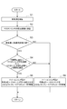
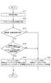
図1を参照して、制動力制御装置1の動作について説明する。特に、ECU5における処理について図4のフローチャートに沿って説明する。図4は、第1の実施の形態に係るECUにおける処理の流れを示すフローチャートである。 The operation of the braking force control device 1 will be described with reference to FIG. In particular, the processing in the ECU 5 will be described along the flowchart of FIG. FIG. 4 is a flowchart showing a process flow in the ECU according to the first embodiment.
各車輪速センサ2A,2B,2C,2Dでは、各輪の回転速度を検出し、各車輪速信号をECU5に送信している。マスタシリンダ圧センサ3では、マスタシリンダMCの油圧を検出し、油圧信号をECU5に送信している。
Each
一定時間毎に、ECU5では、各車輪速センサ2A,2B,2C,2Dからの車輪速信号を受信し、各輪の車輪速を演算し、さらに、車体速を演算する(S1)。また、ECU5では、マスタシリンダ圧センサ3からの油圧信号を受信し、マスタシリンダの昇圧速度を演算する(S2)。
At regular intervals, the ECU 5 receives wheel speed signals from the
ECU5では、車体速が低速判定車体速より低いか否かを判定する(S3)。S3にて車体が低速判定車体速より低いと判定した場合、ECU5では、マスタシリンダの昇圧速度が下限昇圧速度より高くかつ上限昇圧速度より低いか否かを判定する(S4)。 The ECU 5 determines whether the vehicle body speed is lower than the low speed determination vehicle body speed (S3). When it is determined in S3 that the vehicle body is lower than the low speed determination vehicle body speed, the ECU 5 determines whether or not the boosting speed of the master cylinder is higher than the lower limit boosting speed and lower than the upper limit boosting speed (S4).
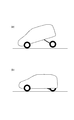
S4にてマスタシリンダの昇圧速度が下限昇圧速度より高くかつ上限昇圧速度より低いと判定した場合(つまり、車両に過大なピッチングが発生すると予測した場合)、ECU5では、目標油圧に(マスタシリンダ圧+加圧分油圧)を設定し、目標油圧になるようにブレーキアクチュエータ4に制御電流を供給する(S5)。すると、ブレーキアクチュエータ4では、その制御電流に応じて作動し、各輪のホイールシリンダWCA,WCB,WCC,WCDで目標油圧に相当する油圧を発生させる。これによって、各輪のホイールシリンダWCA,WCB,WCC,WCDでは、油圧がマスタシリンダ圧より加圧され、昇圧速度がマスタシリンダMCの昇圧速度より大きくなる。そのため、制動力増加速度(車両の減速度)も大きくなり、車両ピッチング共振周波数を超え、車両に過大なピッチングが発生しない。この場合、図6(a)に示すように車両が過大なピッチング状態になることなく、図6(b)に示すように車両のピッチングが極力抑制された状態となる。 When it is determined in S4 that the boosting speed of the master cylinder is higher than the lower limit boosting speed and lower than the upper limit boosting speed (that is, when it is predicted that excessive pitching will occur in the vehicle), the ECU 5 sets the target hydraulic pressure (master cylinder pressure). (+ Pressurized hydraulic pressure) is set, and a control current is supplied to the brake actuator 4 so as to reach the target hydraulic pressure (S5). Then, the brake actuator 4 operates according to the control current, and generates a hydraulic pressure corresponding to the target hydraulic pressure in the wheel cylinders WCA, WCB, WCC, WCD of each wheel. As a result, in the wheel cylinders WCA, WCB, WCC, and WCD of each wheel, the hydraulic pressure is increased from the master cylinder pressure, and the pressure increase speed is greater than the pressure increase speed of the master cylinder MC. Therefore, the braking force increase speed (vehicle deceleration) also increases, exceeds the vehicle pitching resonance frequency, and excessive pitching does not occur in the vehicle. In this case, the vehicle is not excessively pitched as shown in FIG. 6 (a), and the vehicle's pitching is suppressed as much as possible as shown in FIG. 6 (b).
S3にて車体速が低速判定車体速以上と判定した場合あるいはS4にてマスタシリンダの昇圧速度が下限昇圧速度以下又は上限昇圧速度以上と判定した場合(つまり、車両に過大なピッチングが発生しないと予測した場合)、ECU5では、目標油圧にマスタシリンダ圧を設定し、目標油圧になるようにブレーキアクチュエータ4に制御電流を供給する(S6)。すると、ブレーキアクチュエータ4では、その制御電流に応じて作動し、各輪のホイールシリンダWCA,WCB,WCC,WCDで目標油圧に相当する油圧を発生させる。これによって、各輪のホイールシリンダWCA,WCB,WCC,WCDでは、油圧がマスタシリンダ圧となり、昇圧速度がマスタシリンダMCの昇圧速度と同等となる。 If it is determined in S3 that the vehicle body speed is greater than or equal to the low vehicle speed, or if it is determined in S4 that the boosting speed of the master cylinder is less than the lower limit boosting speed or greater than the upper limit boosting speed (that is, if excessive pitching does not occur in the vehicle) When predicted, the ECU 5 sets the master cylinder pressure as the target hydraulic pressure, and supplies a control current to the brake actuator 4 so as to reach the target hydraulic pressure (S6). Then, the brake actuator 4 operates according to the control current, and generates a hydraulic pressure corresponding to the target hydraulic pressure in the wheel cylinders WCA, WCB, WCC, WCD of each wheel. As a result, in the wheel cylinders WCA, WCB, WCC, and WCD of each wheel, the hydraulic pressure becomes the master cylinder pressure, and the pressure increase speed becomes equal to the pressure increase speed of the master cylinder MC.
この制動力制御装置1によれば、車両に過大なピッチングが発生すると予測した場合にはマスタシリンダ圧に対して加圧してホイールシリンダの昇圧速度を更に上げ、制動力増加速度が車両ピッチング共振周波数から外れるようにすることにより、車両のピッチング方向の共振が抑制あるいは発生しなくなり、ピッチングを効果的に抑制することができる。これによって、車両の乗員は過大なピッチングによる不快感を受けなくなり、乗心地が向上する。 According to this braking force control device 1, when it is predicted that excessive pitching will occur in the vehicle, the pressure increase of the wheel cylinder is further increased by applying pressure to the master cylinder pressure, and the braking force increasing speed is determined by the vehicle pitching resonance frequency. By deviating from the above, resonance in the pitching direction of the vehicle is suppressed or not generated, and pitching can be effectively suppressed. As a result, the vehicle occupant is not subject to discomfort due to excessive pitching, and the riding comfort is improved.
また、制動力制御装置1では、ピッチングを抑制するためにブレーキ油圧を加圧するので、通常より大きな制動力を確保でき、運転者のブレーキ操作に対して十分な減速度を発生させることができる。また、制動力制御装置1では、低速走行時にのみピッチングを抑制するための制動力制御を行うので、過大ピッチングが発生しない車速域において不要な制動力制御を行わない。 Moreover, in the braking force control apparatus 1, since brake hydraulic pressure is pressurized in order to suppress pitching, a braking force larger than usual can be ensured and sufficient deceleration can be generated for the driver's braking operation. Further, since the braking force control device 1 performs the braking force control for suppressing the pitching only at the time of low speed traveling, the unnecessary braking force control is not performed in the vehicle speed range where the excessive pitching does not occur.
図1〜図3を参照して、第2の実施の形態に係る制動力制御装置11について説明する。なお、制動力制御装置11は、第1の実施の形態に係る制動力制御装置1と同様の構成については同一の符号を付し、その説明を省略する。 With reference to FIGS. 1-3, the braking force control apparatus 11 which concerns on 2nd Embodiment is demonstrated. Note that the braking force control device 11 is given the same reference numeral for the same configuration as the braking force control device 1 according to the first embodiment, and a description thereof is omitted.
制動力制御装置11は、制動力制御装置1と比較すると、ピッチングを抑制するために制動力増加速度が小さくなるように制動力を制御する。したがって、制動力制御装置11では、ECUにおける一部の処理とその一部の処理に応じたブレーキアクチュエータの動作が制動力制御装置1と異なる。制動力制御装置11は、車輪速センサ2A,2B,2C,2D、マスタシリンダ圧センサ3、ブレーキアクチュエータ4及びECU15を備えている。
Compared with the braking force control device 1, the braking force control device 11 controls the braking force so that the braking force increase rate becomes smaller in order to suppress pitching. Therefore, in the braking force control device 11, a part of the processing in the ECU and the operation of the brake actuator corresponding to the part of the processing are different from the braking force control device 1. The braking force control device 11 includes
ECU15は、第1の実施の形態に係るECU5と比較すると、ピッチングを抑制する際の目標油圧の設定処理だけが異なる。具体的には、車体速が低速判定車体速より低くかつマスタシリンダの昇圧速度が下限昇圧速度LVと上限昇圧速度HVとの範囲内の場合、ECU15では、目標油圧として基準油圧から減圧分油圧を減算した油圧を設定する。減圧分油圧は、ホイールシリンダ圧をマスタシリンダ圧から嵩下げしてホイールシリンダ圧の昇圧速度(ひいては、制動力増加速度)を小さくし、制動力増加速度を車両ピッチング共振周波数と一致しないようにするための油圧である。減圧分油圧は、下限昇圧速度LVと上限昇圧速度HVとの速度範囲を考慮して一定量として予め設定されてもよいし、あるいは、マスタシリンダ圧と下限昇圧速度LVとの差から可変量として設定されてもよい。 The ECU 15 differs from the ECU 5 according to the first embodiment only in the target oil pressure setting process when suppressing pitching. Specifically, when the vehicle body speed is lower than the low speed determination vehicle body speed and the boosting speed of the master cylinder is within the range between the lower limit boosting speed LV and the upper limit boosting speed HV, the ECU 15 changes the reduced hydraulic pressure from the reference hydraulic pressure as the target hydraulic pressure. Set the subtracted hydraulic pressure. The reduced hydraulic pressure reduces the wheel cylinder pressure from the master cylinder pressure to reduce the wheel cylinder pressure increasing speed (and hence the braking force increasing speed) so that the braking force increasing speed does not coincide with the vehicle pitching resonance frequency. For hydraulics. The reduced hydraulic pressure may be set in advance as a constant amount in consideration of the speed range between the lower limit boost speed LV and the upper limit boost speed HV, or as a variable quantity based on the difference between the master cylinder pressure and the lower limit boost speed LV. It may be set.
目標油圧が(基準油圧−減圧分油圧)の場合、図2(d)に示すように、ホイールシリンダ圧WP3は、マスタシリンダ圧MP2より減圧され、マスタシリンダ圧MP2より緩やか勾配で増加する。これによって、制動力増加速度は、マスタシリンダ圧の昇圧速度より小さくなり、車両ピッチング共振周波数を下回る。 When the target oil pressure is (reference oil pressure-reduced pressure oil pressure), as shown in FIG. 2D, the wheel cylinder pressure WP3 is reduced from the master cylinder pressure MP2 and increases with a gentler gradient than the master cylinder pressure MP2. As a result, the braking force increasing speed becomes smaller than the master cylinder pressure increasing speed and is lower than the vehicle pitching resonance frequency.
図1を参照して、制動力制御装置11の動作について説明する。特に、ECU15における処理について図5のフローチャートに沿って説明する。図5は、第2の実施の形態に係るECUにおける処理の流れを示すフローチャートである。 The operation of the braking force control device 11 will be described with reference to FIG. In particular, the processing in the ECU 15 will be described along the flowchart of FIG. FIG. 5 is a flowchart showing a flow of processing in the ECU according to the second embodiment.
各車輪速センサ2A,2B,2C,2D及びマスタシリンダ圧センサ3では、第1の実施の形態と同様の動作を行う。また、ECU15では、S11〜S14までの処理については第1の実施の形態のS1〜S4までと同様の処理を行う。
The
S14にてマスタシリンダの昇圧速度が下限昇圧速度より高くかつ上限昇圧速度より低いと判定した場合、ECU15では、目標油圧に(マスタシリンダ圧−減圧分油圧)を設定し、目標油圧になるようにブレーキアクチュエータ4に制御電流を供給する(S15)。すると、ブレーキアクチュエータ4では、その制御電流に応じて作動し、各輪のホイールシリンダWCA,WCB,WCC,WCDで目標油圧に相当する油圧を発生させる。これによって、各輪のホイールシリンダWCA,WCB,WCC,WCDでは、油圧がマスタシリンダ圧より減圧され、昇圧速度がマスタシリンダMCの昇圧速度より小さくなる。そのため、制動力増加速度(車両の減速度)も小さくなり、車両ピッチング共振周波数を下回り、車両に過大なピッチングが発生しない。この場合も、第1の実施の形態と同様に、図6(a)に示すように車両が過大なピッチング状態になることなく、図6(b)に示すように車両のピッチングが極力抑制された状態となる。 When it is determined in S14 that the boosting speed of the master cylinder is higher than the lower limit boosting speed and lower than the upper limit boosting speed, the ECU 15 sets (master cylinder pressure minus reduced pressure hydraulic pressure) as the target hydraulic pressure so that the target hydraulic pressure is reached. A control current is supplied to the brake actuator 4 (S15). Then, the brake actuator 4 operates according to the control current, and generates a hydraulic pressure corresponding to the target hydraulic pressure in the wheel cylinders WCA, WCB, WCC, WCD of each wheel. As a result, in the wheel cylinders WCA, WCB, WCC, and WCD of each wheel, the hydraulic pressure is reduced from the master cylinder pressure, and the pressure increase speed becomes smaller than the pressure increase speed of the master cylinder MC. As a result, the braking force increase speed (vehicle deceleration) also becomes smaller, lower than the vehicle pitching resonance frequency, and excessive pitching does not occur in the vehicle. In this case as well, as in the first embodiment, the vehicle is not pitched excessively as shown in FIG. 6A, and the vehicle pitching is suppressed as much as possible as shown in FIG. 6B. It becomes a state.
S13にて車体速が低速判定車体速以上と判定した場合あるいはS14にてマスタシリンダの昇圧速度が下限昇圧速度以下又は上限昇圧速度以上と判定した場合、ECU15では第1の実施の形態のS16と同様の処理を行い、ブレーキアクチュエータ4でも第1の実施の形態と同様の動作を行う。 When it is determined at S13 that the vehicle body speed is greater than or equal to the low vehicle speed determination, or when it is determined at S14 that the boosting speed of the master cylinder is equal to or lower than the lower limit boosting speed or greater than or equal to the upper limit boosting speed, the ECU 15 The same processing is performed, and the brake actuator 4 performs the same operation as in the first embodiment.
この制動力制御装置11によれば、車両に過大なピッチングが発生すると予測した場合にはマスタシリンダ圧に対して減圧してホイールシリンダの昇圧速度を下げ、制動力増加速度が車両ピッチング共振周波数から外れるようにすることにより、第1の実施の形態と同様の効果を奏する。また、制動力制御装置11でも、低速走行時にのみピッチングを抑制するための制動力制御を行うので、第1の実施の形態と同様の効果を奏する。 According to this braking force control device 11, when it is predicted that excessive pitching will occur in the vehicle, the pressure increase rate of the wheel cylinder is reduced by reducing the pressure against the master cylinder pressure, and the braking force increase rate is determined from the vehicle pitching resonance frequency. By deviating, the same effect as the first embodiment can be obtained. Also, the braking force control device 11 performs the braking force control for suppressing the pitching only at the time of low-speed traveling, and thus has the same effect as the first embodiment.
以上、本発明に係る実施の形態について説明したが、本発明は上記実施の形態に限定されることなく様々な形態で実施される。 As mentioned above, although embodiment which concerns on this invention was described, this invention is implemented in various forms, without being limited to the said embodiment.
例えば、本実施の形態ではブレーキアクチュエータによってブレーキ油圧を任意に制御することにより制動力を変化させる構成としたが、ブレーキアシストのようにブレーキ油圧を加圧するなどの他の手段でもよい。また、本実施の形態では制動力を変化させるためにブレーキアクチュエータによってホイールシリンダの油圧を制御する構成としたが、ブレーキブースタによってマスタシリンダの油圧を変化させるなどの他の構成としてもよい。 For example, in the present embodiment, the braking force is changed by arbitrarily controlling the brake hydraulic pressure by the brake actuator. However, other means such as pressurizing the brake hydraulic pressure like a brake assist may be used. Further, in the present embodiment, the configuration is such that the hydraulic pressure of the wheel cylinder is controlled by the brake actuator in order to change the braking force, but other configurations such as changing the hydraulic pressure of the master cylinder by the brake booster may be used.
また、本実施の形態では制動力の増加速度としてマスタシリンダの油圧を検出し、マスタシリンダの昇圧速度を演算する構成としたが、センサによってブレーキペダルのストロークや踏力などの制動力に関する他の量を検出し、その変化速度を演算する構成としてもよいし、あるいは、センサによって制動力に関する量の増加速度を直接検出する構成としてもよい。 In the present embodiment, the master cylinder hydraulic pressure is detected as the braking force increase speed, and the master cylinder pressure increase speed is calculated. However, other amounts related to the braking force such as the stroke of the brake pedal and the pedaling force are detected by the sensor. It is good also as a structure which detects this, and calculates the change speed, or it is good also as a structure which detects directly the increase speed of the quantity regarding a braking force with a sensor.
また、本実施の形態では低速走行中かつブレーキ昇圧速度が車両ピッチング共振周波数に相当する範囲内であった場合にピッチングを抑制するための制動力制御を行う構成としたが、他の車速領域でもピッチングが発生する場合には他の車速領域でもピッチングを抑制するための制動力制御を行ってもよい。 In this embodiment, the braking force control is performed to suppress the pitching when the vehicle is traveling at a low speed and the brake boosting speed is within the range corresponding to the vehicle pitching resonance frequency. When pitching occurs, braking force control for suppressing pitching may be performed in other vehicle speed regions.
1,11…制動力制御装置、2A,2B,2C,2D…車輪速センサ、3…マスタシリンダ圧センサ、4…ブレーキアクチュエータ、5,15…ECU
DESCRIPTION OF SYMBOLS 1,11 ... Braking force control apparatus, 2A, 2B, 2C, 2D ... Wheel speed sensor, 3 ... Master cylinder pressure sensor, 4 ... Brake actuator, 5, 15 ... ECU
Claims (4)
制動力の増加速度を求める制動力増加速度手段を備え、
前記制動力増加速度手段で求めた制動力増加速度が車両のピッチング方向の共振周波数に基づいて設定される所定増加速度範囲内になった場合に制動力増加速度が所定増加速度範囲外になるように制動力を制御することを特徴とする制動力制御装置。 A braking force control device for controlling a braking force acting on a vehicle based on a braking operation by a driver,
A braking force increasing speed means for obtaining an increasing speed of the braking force;
When the braking force increasing speed obtained by the braking force increasing speed means falls within a predetermined increasing speed range set based on the resonance frequency in the pitching direction of the vehicle, the braking force increasing speed is out of the predetermined increasing speed range. A braking force control device characterized by controlling braking force.
前記車速検出手段で検出した車速が所定車速以下の場合に制動力増加速度が所定増加速度範囲外になるように制動力を制御することを特徴とする請求項1〜請求項3のいずれか1項に記載する制動力制御装置。
Vehicle speed detection means for detecting the vehicle speed,
The braking force is controlled such that the braking force increase speed is outside a predetermined increasing speed range when the vehicle speed detected by the vehicle speed detecting means is equal to or lower than a predetermined vehicle speed. The braking force control apparatus described in the item.
Priority Applications (1)
| Application Number | Priority Date | Filing Date | Title |
|---|---|---|---|
| JP2006198524A JP2008024142A (en) | 2006-07-20 | 2006-07-20 | Braking force control device |
Applications Claiming Priority (1)
| Application Number | Priority Date | Filing Date | Title |
|---|---|---|---|
| JP2006198524A JP2008024142A (en) | 2006-07-20 | 2006-07-20 | Braking force control device |
Publications (1)
| Publication Number | Publication Date |
|---|---|
| JP2008024142A true JP2008024142A (en) | 2008-02-07 |
Family
ID=39115226
Family Applications (1)
| Application Number | Title | Priority Date | Filing Date |
|---|---|---|---|
| JP2006198524A Pending JP2008024142A (en) | 2006-07-20 | 2006-07-20 | Braking force control device |
Country Status (1)
| Country | Link |
|---|---|
| JP (1) | JP2008024142A (en) |
Cited By (6)
| Publication number | Priority date | Publication date | Assignee | Title |
|---|---|---|---|---|
| JP2013154801A (en) * | 2012-01-31 | 2013-08-15 | Nissan Motor Co Ltd | Control device of vehicle |
| JP2014108733A (en) * | 2012-12-03 | 2014-06-12 | Nissan Motor Co Ltd | Braking/driving force control device for vehicle |
| USD844722S1 (en) | 2017-11-10 | 2019-04-02 | Karsten Manufacturing Corporation | Golf club head |
| USD892954S1 (en) | 2019-01-17 | 2020-08-11 | Karsten Manufacturing Corporation | Golf club head |
| USD930095S1 (en) | 2020-01-31 | 2021-09-07 | Karsten Manufacturing Corporation | Golf club head |
| CN113944711A (en) * | 2020-07-17 | 2022-01-18 | 丰田自动车株式会社 | Brake pad state estimation device and brake pad state estimation method |
-
2006
- 2006-07-20 JP JP2006198524A patent/JP2008024142A/en active Pending
Cited By (7)
| Publication number | Priority date | Publication date | Assignee | Title |
|---|---|---|---|---|
| JP2013154801A (en) * | 2012-01-31 | 2013-08-15 | Nissan Motor Co Ltd | Control device of vehicle |
| JP2014108733A (en) * | 2012-12-03 | 2014-06-12 | Nissan Motor Co Ltd | Braking/driving force control device for vehicle |
| USD844722S1 (en) | 2017-11-10 | 2019-04-02 | Karsten Manufacturing Corporation | Golf club head |
| USD892954S1 (en) | 2019-01-17 | 2020-08-11 | Karsten Manufacturing Corporation | Golf club head |
| USD930095S1 (en) | 2020-01-31 | 2021-09-07 | Karsten Manufacturing Corporation | Golf club head |
| CN113944711A (en) * | 2020-07-17 | 2022-01-18 | 丰田自动车株式会社 | Brake pad state estimation device and brake pad state estimation method |
| CN113944711B (en) * | 2020-07-17 | 2024-02-06 | 丰田自动车株式会社 | Brake pad state estimating device and brake pad state estimating method |
Similar Documents
| Publication | Publication Date | Title |
|---|---|---|
| CN107709125B (en) | Acceleration and deceleration control device | |
| JP6842568B2 (en) | Brake device for saddle-riding vehicles | |
| US10926794B2 (en) | Vehicular behavior control apparatus | |
| JP5405441B2 (en) | Vehicle control device | |
| JP5850186B2 (en) | Vehicle center-of-gravity state determination device and vehicle behavior control system | |
| JP5471078B2 (en) | Vehicle motion control device | |
| JP5431745B2 (en) | Vehicle motion control device | |
| CN111016883B (en) | Vehicle brake control device | |
| JP5999047B2 (en) | Vehicle control device | |
| JP6672769B2 (en) | Braking force control device | |
| JP6213020B2 (en) | Vehicle control device | |
| US20110264349A1 (en) | Travel controlling apparatus of vehicle | |
| JP2011105096A (en) | Vehicle dynamics control device | |
| JP2007008450A (en) | Method for adjusting driving dynamics of automobile | |
| JP2008024142A (en) | Braking force control device | |
| JP5333245B2 (en) | Vehicle behavior control device | |
| JP2005271821A (en) | Vehicular behavior control device | |
| KR20160049213A (en) | Braking pressure control apparatus and method for vehicle | |
| JP2003519590A (en) | Method for improving the steerability and / or running stability of a vehicle when traveling on a curve | |
| US20140142831A1 (en) | Braking force control system for vehicle | |
| KR100774122B1 (en) | Vehicle stability control method | |
| JP5209589B2 (en) | Brake hydraulic pressure control device for vehicles | |
| JP4634952B2 (en) | Brake control device for motorcycle | |
| JP5573384B2 (en) | Vehicle travel control apparatus and method | |
| JP6094307B2 (en) | Brake control device for vehicle |