JP2008024176A - Shock absorption structure for vehicles - Google Patents
Shock absorption structure for vehicles Download PDFInfo
- Publication number
- JP2008024176A JP2008024176A JP2006199603A JP2006199603A JP2008024176A JP 2008024176 A JP2008024176 A JP 2008024176A JP 2006199603 A JP2006199603 A JP 2006199603A JP 2006199603 A JP2006199603 A JP 2006199603A JP 2008024176 A JP2008024176 A JP 2008024176A
- Authority
- JP
- Japan
- Prior art keywords
- damper
- vehicle
- vehicle body
- shock absorbing
- support member
- Prior art date
- Legal status (The legal status is an assumption and is not a legal conclusion. Google has not performed a legal analysis and makes no representation as to the accuracy of the status listed.)
- Pending
Links
Images



Classifications
-
- B—PERFORMING OPERATIONS; TRANSPORTING
- B60—VEHICLES IN GENERAL
- B60G—VEHICLE SUSPENSION ARRANGEMENTS
- B60G2204/00—Indexing codes related to suspensions per se or to auxiliary parts
- B60G2204/10—Mounting of suspension elements
- B60G2204/12—Mounting of springs or dampers
- B60G2204/128—Damper mount on vehicle body or chassis
-
- B—PERFORMING OPERATIONS; TRANSPORTING
- B60—VEHICLES IN GENERAL
- B60G—VEHICLE SUSPENSION ARRANGEMENTS
- B60G2204/00—Indexing codes related to suspensions per se or to auxiliary parts
- B60G2204/10—Mounting of suspension elements
- B60G2204/12—Mounting of springs or dampers
- B60G2204/129—Damper mount on wheel suspension or knuckle
-
- B—PERFORMING OPERATIONS; TRANSPORTING
- B60—VEHICLES IN GENERAL
- B60G—VEHICLE SUSPENSION ARRANGEMENTS
- B60G2204/00—Indexing codes related to suspensions per se or to auxiliary parts
- B60G2204/10—Mounting of suspension elements
- B60G2204/12—Mounting of springs or dampers
- B60G2204/13—Mounting of springs or dampers with the spring, i.e. coil spring, or damper horizontally mounted
-
- B—PERFORMING OPERATIONS; TRANSPORTING
- B60—VEHICLES IN GENERAL
- B60G—VEHICLE SUSPENSION ARRANGEMENTS
- B60G2204/00—Indexing codes related to suspensions per se or to auxiliary parts
- B60G2204/10—Mounting of suspension elements
- B60G2204/15—Mounting of subframes
-
- B—PERFORMING OPERATIONS; TRANSPORTING
- B60—VEHICLES IN GENERAL
- B60G—VEHICLE SUSPENSION ARRANGEMENTS
- B60G2204/00—Indexing codes related to suspensions per se or to auxiliary parts
- B60G2204/40—Auxiliary suspension parts; Adjustment of suspensions
- B60G2204/421—Pivoted lever mechanisms for mounting suspension elements, e.g. Watt linkage
-
- B—PERFORMING OPERATIONS; TRANSPORTING
- B60—VEHICLES IN GENERAL
- B60G—VEHICLE SUSPENSION ARRANGEMENTS
- B60G2206/00—Indexing codes related to the manufacturing of suspensions: constructional features, the materials used, procedures or tools
- B60G2206/01—Constructional features of suspension elements, e.g. arms, dampers, springs
- B60G2206/60—Subframe construction
- B60G2206/604—Subframe construction with two parallel beams connected by cross members
Landscapes
- Body Structure For Vehicles (AREA)
- Vehicle Body Suspensions (AREA)
- Fluid-Damping Devices (AREA)
Abstract
【課題】衝撃が入力されたときの車体の変形および振動を抑制すると共に、車体の車幅方向スペースを大きく確保する。
【解決手段】往復動によって衝撃を吸収する前後の各ダンパ20,21が、前後方向に伸ばした状態で水平に配置され、その前後方向一端部がジョイントを介して車体に取り付けられたサブフレーム10bに連結される。車輪支持部材13が、サスペンションアーム14、15等によって上下方向に揺動可能として車体に支持される。この車輪支持部材13の上下動が、連結ロッド51、揺動レバー50を介して、前記前後方向に伸ばした状態で水平に配置されたダンパ20、21の他端部に伝達される。ダンパ20、21は、車両衝突時の過大な衝撃により破断されて油路を開き衝撃吸収能力を増加させるヒューズバルブを持つ。
【選択図】図2An object of the present invention is to suppress deformation and vibration of a vehicle body when an impact is input, and to secure a large space in the vehicle width direction of the vehicle body.
Sub-frames 10b in which front and rear dampers 20 and 21 absorbing shocks by reciprocating motion are horizontally arranged in a state of extending in the front-rear direction, and one end in the front-rear direction is attached to the vehicle body via a joint. Connected to The wheel support member 13 is supported by the vehicle body so as to be swingable in the vertical direction by the suspension arms 14 and 15. This vertical movement of the wheel support member 13 is transmitted via the connecting rod 51 and the swing lever 50 to the other ends of the dampers 20 and 21 that are horizontally disposed in the state of extending in the front-rear direction. The dampers 20 and 21 have a fuse valve that is broken by an excessive impact at the time of a vehicle collision and opens an oil passage to increase the shock absorbing capacity.
[Selection] Figure 2
Description
本発明は、ダンパによって車体に入力される衝撃を吸収するようにした車両用衝撃吸収構造に関するものである。 The present invention relates to an impact absorbing structure for a vehicle that absorbs an impact input to a vehicle body by a damper.
車両、特に自動車においては、車輪が取付けられる車輪支持部材が、サスペンションアームを介して車体に上下動可能に支持されている。そして、走行に伴って入力される上下方向の衝撃を吸収するために、ダンパが用いられている。このダンパは、サスペンションダンパと呼ばれて、特許文献1に示すように、ほぼ上下方向に伸ばした状態で、その下端部が車輪支持部材あるいはサスペンションアームに連結される一方、その上端部が車体に形成されたサスペンションタワー部に連結される。そして、ダンパは、その周囲を取り巻くように配設されたサスペンションスプリングによって伸び方向に付勢されている。
ところで、車体は共振モードを有しているが、ダンパの取付部となるサスペンションタワー部は、共振される車体の腹部分(変形され易い部分)に位置されることになる。したがって、車輪支持部材を介して衝撃が入力されたときに、車体が曲げ変形やねじり変形され易いものとなり、このことは、操縦安定性を阻害したり振動発生の原因となる。また、サスペンションタワー部は、かなり大きな容積を占めると共に、少なからず車幅方向内方側に大きく張り出した構造とされるために、車室を狭めたり、エンジン等の各種装備品を配設するスペースを大きく犠牲にしている存在となっている。 By the way, although the vehicle body has a resonance mode, the suspension tower portion serving as the attachment portion of the damper is located at the belly portion (the portion that is easily deformed) of the vehicle body to be resonated. Therefore, when an impact is input through the wheel support member, the vehicle body is easily bent or torsionally deformed, which hinders steering stability or causes vibration. In addition, the suspension tower occupies a considerably large volume and has a structure that protrudes to the inner side in the vehicle width direction, so it is a space for narrowing the passenger compartment and installing various equipment such as engines. Has become a great sacrifice.
本発明は以上のような事情を勘案してなされたもので、その目的は、ダンパの配設態様を工夫することにより、衝撃が入力されたときの車体の変形および振動を抑制すると共に、車体の車幅方向スペースを大きく確保できるようにした車両用衝撃吸収構造を提供することにある。 The present invention has been made in view of the circumstances as described above, and its object is to devise the arrangement of the damper to suppress deformation and vibration of the vehicle body when an impact is input, An object of the present invention is to provide a shock absorbing structure for a vehicle that can secure a large space in the vehicle width direction.
前記目的を達成するため、本発明にあっては次のような解決手法を採択してある。すなわち、特許請求の範囲における請求項1に記載のように、
往復動される衝撃吸収用のダンパによって車体に入力される衝撃を吸収するようにした車両用衝撃吸収構造において、
前記ダンパが、車体前後方向に伸ばした状態で、その前後方向一端部が車体に連結され、
サスペンションアームによって上下方向に揺動可能として車体に支持された車輪支持部材が、連結機構を介して前記ダンパの前後方向他端部に連結され、
前記連結機構は、前記車輪支持部材の上下動を前記ダンパの往復動として伝達するように設定されている、
ようにしてある。
In order to achieve the above object, the following solution is adopted in the present invention. That is, as described in claim 1 in the claims,
In the shock absorbing structure for a vehicle that absorbs the shock input to the vehicle body by a shock absorbing damper that is reciprocated,
With the damper extending in the longitudinal direction of the vehicle body, one end in the longitudinal direction is connected to the vehicle body,
A wheel support member supported by the vehicle body so as to be swingable in the vertical direction by the suspension arm is connected to the other end in the front-rear direction of the damper via a connection mechanism,
The coupling mechanism is set to transmit the vertical movement of the wheel support member as a reciprocating movement of the damper.
It is like that.
上記解決手法によれば、ダンパは前後方向でもって衝撃を吸収することになるが、車体は前後方向の強度(剛性)が大きいために、ダンパに衝撃が入力されたときに車体の大きな変形や振動発生がしにくいものとなり、乗り心地の改善や操縦安定性向上を図ることができる。また、従来必要であった大きな容積を占めるサスペンションタワー部が不用になるため、この分車幅方向のスペースを拡大することができる。 According to the above solution, the damper absorbs the impact in the front-rear direction. However, since the vehicle body has high strength (rigidity) in the front-rear direction, when the impact is input to the damper, Vibrations are less likely to occur, improving ride comfort and handling stability. In addition, since the suspension tower that occupies a large volume, which has been necessary in the past, is unnecessary, the space in the vehicle width direction can be expanded.
上記解決手法を前提とした好ましい態様は、特許請求の範囲における請求項2以下に記載のとおりである。すなわち、
前記ダンパの前後方向一端部が、車体に取付けられるサブフレームに連結されている、ようにしてある(請求項2対応)。この場合、ダンパの車体への取付けを、サブフレームの車体への取付けを利用して行うことができ、生産性向上を図る上で好ましいものとなる。また、強度的に優れたサブフレームを利用したダンパの取付けにより、NVHの改善の上でも好ましいものとなる。
A preferred mode based on the above solution is as described in claim 2 and the following claims. That is,
One end of the damper in the front-rear direction is connected to a subframe attached to the vehicle body (corresponding to claim 2). In this case, the damper can be attached to the vehicle body by utilizing the attachment of the subframe to the vehicle body, which is preferable for improving productivity. In addition, it is preferable to improve NVH by attaching a damper using a subframe having excellent strength.
前記ダンパが、所定以上の大きな衝撃が入力されたときに破断されて該大きな衝撃を吸収するためのヒューズバルブを備えている、ようにしてある(請求項3対応)。この場合、前後方向の衝突時におけるような大きな衝撃が入力されたときに、ダンパによって衝撃を吸収させることが可能となる。 The damper is provided with a fuse valve that is broken when a large impact greater than a predetermined value is input to absorb the large impact (corresponding to claim 3). In this case, when a large impact is input as in the front-rear direction collision, the impact can be absorbed by the damper.
前記ダンパが、シリンダと、該シリンダ内に摺動自在に嵌合されたピストンと、該ピストンに一体化されて該シリンダの外部に延在するピストンロッドとを有して、該ピストンロッドの該シリンダに対する往復動によって衝撃を吸収するように設定されており、
前記ヒューズバルブが、前記シリンダまたはピストンに設けられている、
ようにしてある(請求項4対応)。この場合、ダンパとして、サスペンションダンパとして従来使用されてきた汎用品を利用しつつ、衝突時における大きな衝撃を吸収することができる。
The damper includes a cylinder, a piston slidably fitted in the cylinder, and a piston rod integrated with the piston and extending to the outside of the cylinder. It is set to absorb the impact by reciprocating movement with respect to the cylinder,
The fuse valve is provided in the cylinder or piston;
(Corresponding to claim 4). In this case, a large impact at the time of a collision can be absorbed while using a general-purpose product that has been conventionally used as a suspension damper.
前記連結機構が、一端部が前記車輪支持部材に連結され、他端部が前記ダンパに連結されたリンク機構によって構成されている、ようにしてある(請求項5対応)。この場合、車輪支持部材の上下動を、リンク機構によって、直接かつ確実にダンパを往復動させる動きとして伝達することができる。 The connection mechanism is configured by a link mechanism having one end connected to the wheel support member and the other end connected to the damper (corresponding to claim 5). In this case, the vertical movement of the wheel support member can be transmitted as a movement of reciprocating the damper directly and reliably by the link mechanism.
前記連結機構が、一端部が前記サスペンションアームに連結され、他端部が前記ダンパに連結されたリンク機構によって構成されている、ようにしてある(請求項6対応)。この場合、車輪支持部材の上下動を、サスペンションアームを介して、リンク機構という簡単な構成によって、ダンパを往復動させる動きとして伝達することができる。 The connection mechanism is configured by a link mechanism having one end connected to the suspension arm and the other end connected to the damper (corresponding to claim 6). In this case, the vertical movement of the wheel support member can be transmitted through the suspension arm as a movement for reciprocating the damper with a simple structure called a link mechanism.
前記サブフレームが、車幅方向に延びる前後一対の横フレーム部を有し、
前記ダンパの一端部が前記一対の横フレーム部の一方に連結され、
前記ダンパの他端部が、前記一対の横フレーム部の他方に臨んでいる、
ようにしてある(請求項7対応)。この場合、前後方向の衝突時に、ダンパを強度的に優れた横フレーム部に前後方向から当接させて、衝突時の大きな衝撃を効果的に吸収させることができる。
The sub-frame has a pair of front and rear horizontal frame portions extending in the vehicle width direction;
One end portion of the damper is connected to one of the pair of horizontal frame portions,
The other end of the damper faces the other of the pair of horizontal frame portions,
(Corresponding to claim 7). In this case, at the time of the collision in the front-rear direction, the damper can be brought into contact with the lateral frame portion excellent in strength from the front-rear direction to effectively absorb a large impact at the time of the collision.
前記ダンパの前後方向一端部が、車体に取付けられるサブフレームに連結され、 前記サスペンションアームの車幅方向内端部が前記サブフレームに連結され、
前記ダンパを伸び方向に付勢するサスペンションスプリングが、該ダンパを取り巻くように配設され、
前記連結機構が、前記サブフレームに揺動可能に取付けられると共にその一端部が前記ダンパの他端部に連結された揺動レバーと、該揺動レバーの他端部を前記車輪支持部材またはサスペンションアームに連結する連結ロッドと、を備えている、
ようにしてある(請求項8対応)。この場合、サスペンションアーム、ダンパとサスペンションスプリングとのセット体、さらには連結機構があらかじめ組み込まれたサブフレームを車体に組み付けることが可能となり、生産性向上の上で極めて好ましいものとなる。
One end portion in the front-rear direction of the damper is connected to a subframe attached to a vehicle body, and an inner end portion in the vehicle width direction of the suspension arm is connected to the subframe,
A suspension spring for urging the damper in the extending direction is disposed so as to surround the damper,
The coupling mechanism is swingably attached to the subframe and has one end connected to the other end of the damper, and the other end of the swing lever is connected to the wheel support member or the suspension. A connecting rod connected to the arm,
This is done (corresponding to claim 8). In this case, a suspension arm, a set body of a damper and a suspension spring, and a subframe in which a coupling mechanism is incorporated in advance can be assembled to the vehicle body, which is extremely preferable in terms of productivity improvement.
前記揺動レバーは、その揺動中心から前記ダンパの他端部との連結部までの長さが、その揺動中心から前記連結ロッドとの連結部までの長さよりも長くなるように設定されている、ようにしてある(請求項9対応)。この場合、ダンパの往復ストロークを極力大きくして、衝撃を効果的に吸収する上で好ましいものとなる。 The swing lever is set such that the length from the swing center to the connecting portion with the other end of the damper is longer than the length from the swing center to the connecting portion with the connecting rod. (Corresponding to claim 9). In this case, it is preferable to increase the reciprocating stroke of the damper as much as possible to effectively absorb the impact.
本発明によれば、衝撃が入力されたときの車体の変形および振動を抑制できると共に、車体の車幅方向スペースを大きく確保できる。 According to the present invention, it is possible to suppress deformation and vibration of the vehicle body when an impact is input, and to secure a large space in the vehicle width direction of the vehicle body.
図1において、自動車1の車体は、いわゆるモノコック構造とされて、車室2の左右底部において前後方向に伸びる強度部材としてのサイドシル3と、各サイドシル3の前端部から前方へ伸びる左右一対のフロントフレーム4と、各サイドシル3の後端部から後方へ伸びる左右一対のリアフレーム5とを有する。
In FIG. 1, the body of the automobile 1 has a so-called monocoque structure, and a side sill 3 as a strength member extending in the front-rear direction at the left and right bottoms of the passenger compartment 2 and a pair of left and right fronts extending forward from the front end of each side sill 3 It has a
フロントフレーム4に対しては前サブフレーム10が取付けられ、リアフレーム5に対しては後サブフレーム11が取付けられている。各サブフレーム10、11はそれぞれ、既知のように、ゴムブッシュ等を介してフレーム4あるいは5に固定されている。
A
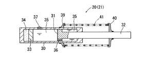
前サブフレーム10には、左右一対の前ダンパ20が取付けられ、後サブフレーム11には、左右一対の後ダンパ21が取付けられている。各ダンパ20,21は同様に構成されているので、前ダンパ20に着目して、その一例について図4を参照しつつ説明する。図4において、30はシリンダで、シリンダ30内にはピストン31が摺動自在に嵌合されている。ピストン31に一体化されたピストンロッド32が、シリンダ30の一端部を液密に貫通してシリンダ30の外部に延在されている。また、シリンダ30内には、ピストンロッド32とは反対側において、フリーピストン33が摺動自在に嵌合されている。
A pair of left and right
シリンダ30内は、フリーピストン33とシリンダ30の底部との間に、所定圧力のガスが充填されたガス室34とされ、シリンダ30内のうちガス室34以外の部分は、オイルが充満されたオイル室35とされている。そして、ピストン31には、ピストン31のシリンダ30に対する摺動に応じてオイルが行き来して衝撃吸収を行うためのオリフィス36が形成されている。このオリフィス36は、後述するように、走行中に生じる車輪の上下動に伴う衝撃を吸収するのに適したものに設定されている。また、シリンダ30の側壁には、ヒューズバルブ37が設けられている。このヒューズバルブ37は、前後方向の衝突時などの極めて大きな衝撃が入力されたときに破断されて、オイル室35内のオイルを外部へ逃がすことにより、衝撃吸収作用を行うようになっている。
The inside of the
シリンダ30の外壁には、スプリング受け39が固定される一方、ピストンロッド32の先端部付近にはスプリング受け40が固定されている。そして、両スプリング受け39と40との間に、前ダンパ20を取り巻くように配設されたコイルスプリングからなるサスペンションスプリング41が張設されている。このサスペンションスプリング41によって、前ダンパ20は、常時伸び方向に付勢されている。
A
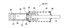
図5は、図4の変形例を示すものであり、ヒューズバルブ37を、ピストン31に設けたものである。すなわち、前後方向の衝突時のような極めて大きな衝撃が入力されたときに、ヒューズバルブ37が破断されて、ピストン31によって画成された2つのオイル室35同士が大きな有効開口面積でもって連通されて、大きな衝撃が吸収されることになる。なお、図4,図4の場合共に、オリフィス36としては、ダンパ20(21)の伸び方向用と縮み方向用とで同じような衝撃吸収を行うように設定されいるが、例えば伸び方向専用のオリフィスと縮方向専用のオリフィスを設けたものであってもよい。また、図4、図5の例では、いわゆる単筒式とした場合が示されるが、複筒式等、従来サスペンションダンパとして使用されてきた各種形式のダンパを用いることができる(ただし、前後方向の衝突時のような大きな衝撃吸収を行うためには、汎用品のサスペンションダンパに対してヒューズバルブ37を別途設ければよい)。
FIG. 5 shows a modification of FIG. 4, in which a
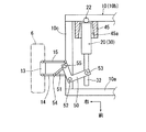
次に、図2,図6,図7を参照しつつ、前サブフレーム10に着目して、前ダンパ20の配設態様や、前輪6と前ダンパ20との連結態様等について説明する。なお、図1では簡略化のためにサブフレーム10,11を省略してある。また、後サブフレーム11についても実質的に同様に構成されているものである。
Next, with reference to FIGS. 2, 6, and 7, focusing on the
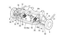
まず、前サブフレーム10は、車幅方向に伸びる前フレーム部10a、後フレーム部10bと、前後のフレーム部10aと10bとの車幅方向端部同士を連結する前後方向に伸びる左右一対の横フレーム部10c、10dとを有して、平面視において、周囲が閉じられた枠形状を構成している。このような前サブフレーム10は、金属製とされて、剛性が十分に大きいものとされている。
First, the
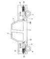
図2は、前サブフレーム10に対して組付られた左右一対の前ダンパ20と、左右の前輪6との連結態様の全体を示すものである。この図2において、前輪6が取付けられる車輪支持部材13が、車幅方向に伸びる前後一対のロアアーム14、15によって、上下方向に揺動可能として前サブフレーム10に取付けられている。また、車輪支持部材13は、車幅方向に伸びる1本のアッパアーム16によって車体1に連結され、さらに前後方向に伸びるリンク17によって車体1に連結されている。なお、各アーム14〜16およびリンク17は、既知のように、車輪支持部材13や前サブフレーム10さらには車体1に対して、弾性ブッシュあるいはボールジョイントを介して連結されている。
FIG. 2 shows the entire connection mode of the pair of left and right
左右一対の前ダンパ20は、ピストンロッド32が前向きの状態となるようにして、前後方向に伸ばして配設されている。前ダンパ20は、そのシリンダ30の端部において、ボールジョイント22を介して、後フレーム部10bに対して、通常のサスペンションストローク時に前ダンパ20に過大な(無理な)曲げ入力が作用されないようにして連結されている。前ダンパ20は、そのピストンロッド32が前向きの状態とされるが、ピストンロッド32の先端面は、前フレーム部10aに対して臨まされている。すなわち、前後方向の衝突時に前後のフレーム部10aと10bとが接近されるような変形作用を受けたときに、前ダンパ20が圧縮作用を受けるような配設態様とされている。
The pair of left and right
右側に位置される前ダンパ20が右前輪6用とされ、左側に位置される前ダンパ20が左前輪6用とされる。そして、車輪支持部材13と前ダンパ20のピストンロッド32とが、リンク機構からなる連結機構Rを介して連結されている。連結機構Rによって、前輪6つまり車輪支持部材13が上下動されたとき、前ダンパ20が往復動されて、衝撃吸収を行うようになっている。
The
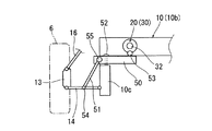
上記連結機構Rの一例について、図6,図7をも参照しつつ説明する。なお、図6、図7では、サスペンションスプリング41を省略してある。また、左右対称構造とされているので、右前輪6に着目して連結機構Rについて説明することとする。
An example of the coupling mechanism R will be described with reference to FIGS. 6 and 7, the
まず、連結機構Rは、揺動レバー50と、連結ロッド51とを有する。揺動レバー50は、前サブフレーム10における横フレーム部10cに対して、ジョイント52を介して水平方向に揺動自在に取付けられている。揺動レバー50の一端部50aは、ボールジョイント53を介して、ピストンロッド32の先端部付近に連結されている。
First, the connecting mechanism R includes a
連結ロッド51は、車輪支持部材13と揺動レバー50とを連結するもので、車幅方向に伸びているが、車幅方向外方側に向かうにつれて徐々に下方に位置するように傾斜されている。この連結ロッド51の車幅方向外端部が、ロアアーム14に対して、ボールジョイント54を介して連結されている。また、連結ロッド51の車幅方向内端部が、揺動レバー50の他端部50bに対して、ボールジョイント55を介して連結されている。揺動レバー50のレバー比、つまり、その揺動中心となるジョイント52とピストンロッド32への連結部位となるボールジョイント53との間の距離が、ジョイント52と連結ロッド51への連結部位となるボールジョイント55との間の距離よりも大きくなるように設定されている。すなわち、連結ロッド51による小さな変位が、拡大されてピストンロッド32へ伝達されるように設定されている。
The connecting
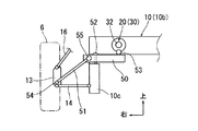
図8,図9は、図6,C図7の変形例を示すものであり、連結ロッド51の車幅方向外端部を、ロアアーム14に代えて車輪支持部材134に連結したものである。本変形例の場合においても、前輪6の上下動が、連結ロッド51,揺動レバー50を介して、ピストンロッド32を往復動させる動きとして伝達される。
FIGS. 8 and 9 show modified examples of FIGS. 6 and 7, in which the outer end portion of the connecting
以上は、前輪6に関連した構造に着目した場合であるが、後輪7についても同様に構成されている。すなわち、図3に示すように、左右一対の後ダンパ21は、それぞれ前後方向に伸ばした状態で、後サブフレーム11に対して連結されている。ただし、前ダンパ20の場合とは逆に、ピストンロッド32が後ろ向きとなる状態でもって配設されている。後サブフレーム11は、車幅方向に伸びる左右一対の前フレーム部11a、11bと、前後のフレーム部11aと11bの車幅方向端部同士を連結する前後方向に伸びる左右一対の横フレーム部11c、11dとを有して、平面視において、周囲が閉じられた枠形状を構成している。このような後サブフレーム11は、金属製とされて、剛性が十分に大きいものとされている。
The above is a case where attention is paid to the structure related to the
左右一対の後ダンパ21は、そのシリンダ30の端部において、ボールジョイント22R(前ダンパ20におけるボールジョイント22に相当)を介して、前フレーム部11aに対して、通常のサスペンションストローク時に後ダンパ21に過大な(無理な)曲げ入力が作用されないようにして連結されている。後ダンパ21は、そのピストンロッド32が前向きの状態とされるが、ピストンロッド32の先端面は、後フレーム部11bに対して臨まされている。すなわち、前後方向の衝突時に前後のフレーム部11aと11bとが接近されるような変形作用を受けたときに、後ダンパ21が圧縮作用を受けるような配設態様とされている。
The pair of left and right
なお、図示を略すが、後輪7(の車輪支持部材)も前輪6の場合と同様にロアアーム等のサスペンションアームによって後サブフレーム11に上下動可能に支持されると共に、前輪6の場合と同様に構成された連結機構Rによって、後輪7用の車輪支持部材あるいはロアアームが、後ダンパ21におけるピストンロッド32の先端部付近に連結されている。
Although not shown, the rear wheel 7 (the wheel support member) is also supported by the
前サブフレーム10は、車輪支持部材13,各サスペンションアーム14〜17,前ダンパ20,サスペンションスプリング41,連結機構Rがあらかじめ組み込まれた状態で、車体1に対して下方から組み付けられる。同様に、後サブフレーム11は、車輪支持部材,各サスペンションアーム,後ダンパ21,サスペンションスプリング41,連結機構があらかじめ組み込まれた状態で、車体1に対して下方から組み付けられる。このように、複数の部材をあらかじめサブフレーム10、11に組み付けておき、その後サブフレーム10、11を車体に組み付けることにより、生産性が大幅に向上されることになる。とりわけ、サブフレーム10あるいは11へは連結されないピストンロッド32が、連結機構R(の揺動レバー50)を介してサブフレーム10あるいは11に位置決めされた状態で保持されるので、ダンパ20、21の車体1への組付性向上の上で極めて好ましいものとなる。
The
次に、以上のような構成の作用について説明する。まず、前後のダンパ20、21は、サスペンションスプリング41によってピストンロッド32が伸び方向に付勢されていることによって、前輪6および後輪7は路面に押しつけられた状態となり、所定の車高が確保される。車両の走行中に生じる前輪6、後輪7の上下動(つまり車輪支持部材13の上下動)が、連結ロッド51を介して揺動レバー50の揺動運動に変換されて、ピストンロッド32が前後方向に往復動される。これにより、走行中に前輪6から入力される衝撃が前ダンパ20によって吸収されると共に、走行中に生じる後輪7から入力される衝撃が後ダンパ21によって吸収されることになる。揺動レバー50の前述したレバー比の設定によって、連結ロッド51の変位が拡大されてピストンロッド32を往復動させることとなり、前後の各ダンパ20、21共に極力大きなストロークが確保されて、衝撃が効果的に吸収されることになる。
Next, the operation of the above configuration will be described. First, the front and
前後方向の衝突時のように、前後方向の極めて大きな荷重が車体に作用して、前後のフレーム部10aと10bあるいは11aと11bとが接近するような変形作用を受けると、ダンパ20あるいは21は極めて大きな荷重でもって圧縮されることになる。このような極めて大きな荷重を受けたときは、ヒューズバルブ37が破断されて、ダンパ20,21による衝撃吸収が行われることになる。なお、衝突態様によっては、前ダンパ20のみが衝撃吸収を行う場合もあり、逆に後ダンパ21のみが衝撃吸収を行う場合もある。
When a very large load in the front-rear direction acts on the vehicle body and the front and
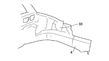
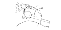
本発明では、車体1に対して、車幅方向内方側に張り出す大容積のサスペンションタワー部が不用となる。図12は、前輪用のサスペンションタワー部STが存在する従来の車体構造例を示すものである。図10は、図12に対応した部分において、サスペンションタワー部STが存在しない状態の一例が示され、図11はサスペンションタワー部STが存在しない状態の別の例が示される。図10の例は、エンジンルームの車幅方向寸法を大きく拡大したものである(ただし、エンジンルームの側壁部60の高さは、サスペンションタワー部STを有する従来構造のものを略同じに設定してある)。また、図11の例では、図10におけるエンジンルームの車幅方向寸法拡大に加えて、エンジンルームの側壁部60の高さを従来構造のものよりも低くしたものである(ボンネット高さを低くできる)。一方、車体後部においては、後輪7用のサスペンションタワー部が不用になることから、例えば、車室の車幅方向寸法拡大や、荷室の車幅方向寸法拡大が可能となる。
In the present invention, a large-capacity suspension tower that protrudes inward in the vehicle width direction with respect to the vehicle body 1 is unnecessary. FIG. 12 shows an example of a conventional vehicle body structure in which a suspension tower ST for front wheels is present. FIG. 10 shows an example of a state where the suspension tower portion ST does not exist in a portion corresponding to FIG. 12, and FIG. 11 shows another example of a state where the suspension tower portion ST does not exist. In the example of FIG. 10, the dimension in the vehicle width direction of the engine room is greatly enlarged (however, the height of the
ここで、前後方向衝突時において、ダンパ20、21によって前後方向の衝撃をより効果的かつ確実に吸収できるようにするため、ダンパ20、21を、通常のサスペンションストロークによって生じる傾斜角度範囲を超えて大きく傾斜されないように設定しておくのが好ましい。例えば、図6において、サブフレーム10(11についても同じ)に対して、ダンパ20(21についても同じ)を取り巻くように、例えば筒状の剛性に優れた傾斜規制部材(ストッパ)45を固定しておくようにしてもよい(傾斜規制部材45は、図7では図示を略す)。図6に示す傾斜規制部材45は、シリンダ20の軸線方向に伸びるその内孔45aが、ピストンロッド32先端部に向かうにつれて徐々に拡大するように設定されて、ダンパ20が所定角度まで傾斜されたときにダンパ20が内孔45a(の内面)に当接されて、ダンパ20がそれ以上大きく傾斜されるのが規制される。なお、ダンパ20が上下方向軸線回りにのみ揺動されるように設定された場合は、傾斜規制部材45を、筒状に構成することなく、ダンパ20を左右方向から挟むような構成として、ダンパ20が所定角度を超えて大きく左方方向に傾斜しないようにすることもできる。また、傾斜規制部材45は、シリンダ30側ではなくて、ピストンロッド32の先端部側に設けるようにすることもできるが、ダンパ20の揺動変位量が相対的に小さくなるシリンダ30側(サブフレーム10への取付端部側)に設けておくのが好ましい。
Here, in order to more effectively and reliably absorb the impact in the front-rear direction by the
以上実施形態について説明したが、本発明は、実施形態に限定されるものではなく、特許請求の範囲の記載された範囲において適宜の変更が可能であり、例えば次のような場合をも含むものである。前後方向の衝突対応を行わない場合であってもよく、この場合はヒューズバルブ37が不用となる。各ボールジョイント部分は、弾性ブッシュ等に適宜置き換えることもできる。前輪6についてのみあるいは後輪7についてのみ本発明を適用するようにしてもよい。ダンパ20、21は、サブフレーム10、11を介することなく、直接的に車体1に連結するようにしてもよい。連結機構Rとしては、車輪支持部材13の上下動を前後動に変換できるものであれば、適宜の構造のものを採択することができる。ダンパ20,21は、そのピストンロッド32女を前向きにするか後向きにするかは適宜選択できる(実施形態とは逆向きとすることができる)。勿論、本発明の目的は、明記されたものに限らず、実質的に好ましいあるいは利点として表現されたものを提供することをも暗黙的に含むものである。
Although the embodiment has been described above, the present invention is not limited to the embodiment, and can be appropriately changed within the scope described in the scope of claims. For example, the invention includes the following cases. . There may be a case where the collision in the front-rear direction is not performed. In this case, the
1:車体
3:サイドシル
4:フロントフレーム
5:リアフレーム
6:前輪
7:後輪
10:前サブフレーム
10a:前フレームぶ
10b:後フレーム部
10c:横フレーム部
10d:横フレーム部
11:後サブフレーム
11a:前フレームぶ
11b:後フレーム部
11c:横フレーム部
11d:横フレーム部
13:車輪支持部材
14,15:ロアアーム
16:アッパアーム
20:前ダンパ
21:後ダンパ
22:ボールジョイント(前ダンパの前サブフレームへの連結部)
22R:ボールジョイント(後ダンパの後サブフレームへの連結部)
30;シリンダ
31:ピストン
32:ピストンロッド
35:オイル室
36:オリフィス(減衰力発生用)
37:ヒューズバルブ
41:サスペンションスプリング
50:揺動レバー
51:連結ロッド
52:ジョイント(揺動レバーの揺動中心)
53:ボールジョイント(揺動レバーとピストンロッドとの連結部)
54:ボールジョイント(連結ロッドと車輪支持部材との連結部)
55:ボールジョイント(連結ロッドと揺動レバーとの連結部)
R;連結機構
1: Car body 3: Side sill 4: Front frame 5: Rear frame 6: Front wheel 7: Rear wheel 10:
22R: Ball joint (rear damper connecting part to rear subframe)
30: Cylinder 31: Piston 32: Piston rod 35: Oil chamber 36: Orifice (for generating damping force)
37: fuse valve 41: suspension spring 50: swing lever 51: connecting rod 52: joint (swing center of swing lever)
53: Ball joint (connecting part of swing lever and piston rod)
54: Ball joint (connecting portion between connecting rod and wheel support member)
55: Ball joint (connecting portion between connecting rod and swing lever)
R; coupling mechanism
Claims (9)
前記ダンパが、車体前後方向に伸ばした状態で、その前後方向一端部が車体に連結され、
サスペンションアームによって上下方向に揺動可能として車体に支持された車輪支持部材が、連結機構を介して前記ダンパの前後方向他端部に連結され、
前記連結機構は、前記車輪支持部材の上下動を前記ダンパの往復動として伝達するように設定されている、
ことを特徴とする車両用衝撃吸収構造。 In the shock absorbing structure for a vehicle that absorbs the shock input to the vehicle body by a shock absorbing damper that is reciprocated,
With the damper extending in the longitudinal direction of the vehicle body, one end in the longitudinal direction is connected to the vehicle body,
A wheel support member supported by the vehicle body so as to be swingable in the vertical direction by the suspension arm is connected to the other end in the front-rear direction of the damper via a connection mechanism,
The coupling mechanism is set to transmit the vertical movement of the wheel support member as a reciprocating movement of the damper.
A shock absorbing structure for a vehicle characterized by that.
前記ダンパの前後方向一端部が、車体に取付けられるサブフレームに連結されている、ことを特徴とする車両用衝撃吸収構造。 In claim 1,
One end of the damper in the front-rear direction is connected to a subframe attached to the vehicle body.
前記ダンパが、所定以上の大きな衝撃が入力されたときに破断されて該大きな衝撃を吸収するためのヒューズバルブを備えている、ことを特徴とする車両用衝撃吸収構造。 In claim 1 or claim 2,
A shock absorbing structure for a vehicle, wherein the damper includes a fuse valve that is broken when a large shock of a predetermined level or more is input and absorbs the large shock.
前記ダンパが、シリンダと、該シリンダ内に摺動自在に嵌合されたピストンと、該ピストンに一体化されて該シリンダの外部に延在するピストンロッドとを有して、該ピストンロッドの該シリンダに対する往復動によって衝撃を吸収するように設定されており、
前記ヒューズバルブが、前記シリンダまたはピストンに設けられている、
ことを特徴とする車両用衝撃吸収構造。 In claim 3,
The damper includes a cylinder, a piston slidably fitted in the cylinder, and a piston rod integrated with the piston and extending to the outside of the cylinder. It is set to absorb the impact by reciprocating movement with respect to the cylinder,
The fuse valve is provided in the cylinder or piston;
A shock absorbing structure for a vehicle characterized by that.
前記連結機構が、一端部が前記車輪支持部材に連結され、他端部が前記ダンパに連結されたリンク機構によって構成されている、ことを特徴とする車両用衝撃吸収構造。 In any one of Claims 1 thru | or 4,
A shock absorbing structure for a vehicle, wherein the connecting mechanism is constituted by a link mechanism having one end connected to the wheel support member and the other end connected to the damper.
前記連結機構が、一端部が前記サスペンションアームに連結され、他端部が前記ダンパに連結されたリンク機構によって構成されている、ことを特徴とする車両用衝撃吸収構造。 In any one of Claims 1 thru | or 4,
A shock absorbing structure for a vehicle, wherein the connection mechanism is constituted by a link mechanism having one end connected to the suspension arm and the other end connected to the damper.
前記サブフレームが、車幅方向に延びる前後一対の横フレーム部を有し、
前記ダンパの一端部が前記一対の横フレーム部の一方に連結され、
前記ダンパの他端部が、前記一対の横フレーム部の他方に臨んでいる、
ことを特徴とする車両用衝撃吸収構造。 In claim 2,
The sub-frame has a pair of front and rear horizontal frame portions extending in the vehicle width direction;
One end portion of the damper is connected to one of the pair of horizontal frame portions,
The other end of the damper faces the other of the pair of horizontal frame portions,
A shock absorbing structure for a vehicle characterized by that.
前記ダンパの前後方向一端部が、車体に取付けられるサブフレームに連結され、 前記サスペンションアームの車幅方向内端部が前記サブフレームに連結され、
前記ダンパを伸び方向に付勢するサスペンションスプリングが、該ダンパを取り巻くように配設され、
前記連結機構が、前記サブフレームに揺動可能に取付けられると共にその一端部が前記ダンパの他端部に連結された揺動レバーと、該揺動レバーの他端部を前記車輪支持部材またはサスペンションアームに連結する連結ロッドと、を備えている、
ことを特徴とする車両用衝撃吸収構造。 In claim 1,
One end portion in the front-rear direction of the damper is connected to a subframe attached to a vehicle body, and an inner end portion in the vehicle width direction of the suspension arm is connected to the subframe,
A suspension spring for urging the damper in the extending direction is disposed so as to surround the damper,
The coupling mechanism is swingably attached to the subframe and has one end connected to the other end of the damper, and the other end of the swing lever is connected to the wheel support member or the suspension. A connecting rod connected to the arm,
A shock absorbing structure for a vehicle characterized by that.
前記揺動レバーは、その揺動中心から前記ダンパの他端部との連結部までの長さが、その揺動中心から前記連結ロッドとの連結部までの長さよりも長くなるように設定されている、ことを特徴とする車両用衝撃吸収構造。
In claim 8,
The swing lever is set such that the length from the swing center to the connecting portion with the other end of the damper is longer than the length from the swing center to the connecting portion with the connecting rod. A shock absorbing structure for a vehicle characterized by that.
Priority Applications (1)
| Application Number | Priority Date | Filing Date | Title |
|---|---|---|---|
| JP2006199603A JP2008024176A (en) | 2006-07-21 | 2006-07-21 | Shock absorption structure for vehicles |
Applications Claiming Priority (1)
| Application Number | Priority Date | Filing Date | Title |
|---|---|---|---|
| JP2006199603A JP2008024176A (en) | 2006-07-21 | 2006-07-21 | Shock absorption structure for vehicles |
Publications (1)
| Publication Number | Publication Date |
|---|---|
| JP2008024176A true JP2008024176A (en) | 2008-02-07 |
Family
ID=39115254
Family Applications (1)
| Application Number | Title | Priority Date | Filing Date |
|---|---|---|---|
| JP2006199603A Pending JP2008024176A (en) | 2006-07-21 | 2006-07-21 | Shock absorption structure for vehicles |
Country Status (1)
| Country | Link |
|---|---|
| JP (1) | JP2008024176A (en) |
Cited By (5)
| Publication number | Priority date | Publication date | Assignee | Title |
|---|---|---|---|---|
| KR101305899B1 (en) | 2011-10-14 | 2013-09-06 | 현대자동차주식회사 | Apparatus for suppressing dipping of vehicle |
| CN111923673A (en) * | 2019-05-13 | 2020-11-13 | 丰田自动车株式会社 | Suspension device for vehicle |
| CN111923674A (en) * | 2019-05-13 | 2020-11-13 | 丰田自动车株式会社 | Suspension device for vehicle |
| CN115370863A (en) * | 2022-10-18 | 2022-11-22 | 江苏圣大中远电力科技有限公司 | Stably-assembled support and hanger |
| JP2023089643A (en) * | 2021-12-16 | 2023-06-28 | ダイハツ工業株式会社 | vehicle structure |
-
2006
- 2006-07-21 JP JP2006199603A patent/JP2008024176A/en active Pending
Cited By (12)
| Publication number | Priority date | Publication date | Assignee | Title |
|---|---|---|---|---|
| KR101305899B1 (en) | 2011-10-14 | 2013-09-06 | 현대자동차주식회사 | Apparatus for suppressing dipping of vehicle |
| CN111923673A (en) * | 2019-05-13 | 2020-11-13 | 丰田自动车株式会社 | Suspension device for vehicle |
| CN111923674A (en) * | 2019-05-13 | 2020-11-13 | 丰田自动车株式会社 | Suspension device for vehicle |
| JP2020185856A (en) * | 2019-05-13 | 2020-11-19 | トヨタ自動車株式会社 | Vehicular suspension device |
| JP2020185857A (en) * | 2019-05-13 | 2020-11-19 | トヨタ自動車株式会社 | Suspension device for vehicle |
| JP7120149B2 (en) | 2019-05-13 | 2022-08-17 | トヨタ自動車株式会社 | Vehicle suspension device |
| US11472249B2 (en) | 2019-05-13 | 2022-10-18 | Toyota Jidosha Kabushiki Kaisha | Suspension device for vehicle |
| JP7188273B2 (en) | 2019-05-13 | 2022-12-13 | トヨタ自動車株式会社 | Vehicle suspension system |
| US11602965B2 (en) | 2019-05-13 | 2023-03-14 | Toyota Jidosha Kabushiki Kaisha | Suspension device for vehicle |
| JP2023089643A (en) * | 2021-12-16 | 2023-06-28 | ダイハツ工業株式会社 | vehicle structure |
| JP7810508B2 (en) | 2021-12-16 | 2026-02-03 | ダイハツ工業株式会社 | Vehicle structure |
| CN115370863A (en) * | 2022-10-18 | 2022-11-22 | 江苏圣大中远电力科技有限公司 | Stably-assembled support and hanger |
Similar Documents
| Publication | Publication Date | Title |
|---|---|---|
| JP4748765B2 (en) | Multilink rear suspension system | |
| US8220807B2 (en) | Passive antiroll device for the suspension of a motor vehicle, and a suspension incorporating it | |
| US7735909B2 (en) | Body reinforcement device for a vehicle | |
| CN103958228B (en) | There is the rigid shaft of air suspension | |
| CN100457481C (en) | Multi-link rear-suspension system | |
| JP2005126034A (en) | Lower arm assembly | |
| WO2013150749A1 (en) | Vehicle main frame and vehicle using same | |
| US20130341881A1 (en) | Suspension device for vehicle, and method for installing shock absorber | |
| KR102745137B1 (en) | Rear suspension device of a vehicle | |
| JP2020100186A (en) | Toe correct bush and rear suspension device | |
| JP2001330076A (en) | Inverted hydraulic shock absorber | |
| CN115503410A (en) | Spring control arm, spring control arm assembly and vehicle | |
| JP2005170269A (en) | Vehicle body structure | |
| JP4356442B2 (en) | Wheel independent suspension system | |
| KR101338429B1 (en) | Sub-frame for front suspension of automobile device for vehicle | |
| KR100820444B1 (en) | Car Torque Rod | |
| CN217753396U (en) | a car suspension | |
| JP4948068B2 (en) | Liquid-filled bush | |
| JP2021160513A (en) | Cab support | |
| CN223443237U (en) | Suspension assembly and vehicle having the same | |
| CN213892085U (en) | A multi-link rear suspension and vehicle | |
| KR100957157B1 (en) | Active roll control system | |
| CN211106926U (en) | Pull rod suspension and vehicle | |
| JP4258446B2 (en) | Wheel support structure | |
| JP2006088999A (en) | Vehicle body structure |