JP2008024340A - Cover member - Google Patents
Cover member Download PDFInfo
- Publication number
- JP2008024340A JP2008024340A JP2006199113A JP2006199113A JP2008024340A JP 2008024340 A JP2008024340 A JP 2008024340A JP 2006199113 A JP2006199113 A JP 2006199113A JP 2006199113 A JP2006199113 A JP 2006199113A JP 2008024340 A JP2008024340 A JP 2008024340A
- Authority
- JP
- Japan
- Prior art keywords
- cover member
- cover
- opening
- panel
- plate
- Prior art date
- Legal status (The legal status is an assumption and is not a legal conclusion. Google has not performed a legal analysis and makes no representation as to the accuracy of the status listed.)
- Granted
Links
Images





Classifications
-
- Y—GENERAL TAGGING OF NEW TECHNOLOGICAL DEVELOPMENTS; GENERAL TAGGING OF CROSS-SECTIONAL TECHNOLOGIES SPANNING OVER SEVERAL SECTIONS OF THE IPC; TECHNICAL SUBJECTS COVERED BY FORMER USPC CROSS-REFERENCE ART COLLECTIONS [XRACs] AND DIGESTS
- Y02—TECHNOLOGIES OR APPLICATIONS FOR MITIGATION OR ADAPTATION AGAINST CLIMATE CHANGE
- Y02A—TECHNOLOGIES FOR ADAPTATION TO CLIMATE CHANGE
- Y02A20/00—Water conservation; Efficient water supply; Efficient water use
- Y02A20/20—Controlling water pollution; Waste water treatment
- Y02A20/208—Off-grid powered water treatment
Abstract
【課題】水処理施設において10mを超える開口スパンの水槽を覆うことができ、設置現場に搬送しやすく、設置現場での組立が容易な覆蓋部材を提供する。
【解決手段】下水処理施設1に設置された沈殿池2の上部に上面視形状が略長方形状を呈した開口部2aが設けられ、開口部2aの周縁を構成する構成壁の側縁部2b,2bに開口部2aを跨いで複数隣接して架け渡すことによって開口部2aの上部を覆う覆蓋部材3であって、
板材によって構成され平面視形状が略長方形状を呈した長尺の2つの覆蓋パネル6と、2つの覆蓋パネル6,6の長手方向一端縁同士を斜めに連結する連結部材7とを有し、2つの覆蓋パネル6,6が連結部材7によって連結されている。
【選択図】図5Provided is a cover member that can cover a water tank having an opening span of more than 10 m in a water treatment facility, can be easily transported to an installation site, and can be easily assembled on the installation site.
An opening 2a having a substantially rectangular shape in a top view is provided on an upper part of a sedimentation basin 2 installed in a sewage treatment facility 1, and a side edge 2b of a constituent wall constituting the periphery of the opening 2a. , 2b, covering the upper part of the opening 2a by bridging a plurality of adjacently straddling the opening 2a,
Two long cover panels 6 that are made of a plate material and have a substantially rectangular shape in plan view, and a connecting member 7 that obliquely connects one end edge in the longitudinal direction of the two cover panels 6 and 6, Two cover panels 6 and 6 are connected by a connecting member 7.
[Selection] Figure 5
Description
本発明は、水処理施設に設置された水槽の上部開口部を覆う覆蓋部材に関する。 The present invention relates to a cover member that covers an upper opening of a water tank installed in a water treatment facility.
例えば、下水処理施設には、沈砂槽、沈殿槽、生物反応槽などの水槽が配置されている。 For example, water tanks such as a sand settling tank, a settling tank, and a biological reaction tank are arranged in a sewage treatment facility.
これらの水槽の上部開口部は、安全上、衛生上、或いは、環境上などの観点から覆蓋部材によって覆われている。 The upper openings of these water tanks are covered with a cover member from the viewpoints of safety, hygiene, and environment.
水槽の上部には上面視形状が略長方形状を呈した開口部が設けられており、開口部の周縁を構成する構成壁の上縁部に、開口部を跨いで複数の覆蓋部材を隣接させて架け渡すことによって開口部の上部を覆っている。 The upper part of the water tank is provided with an opening having a substantially rectangular shape when viewed from above, and a plurality of cover members are disposed adjacent to the upper edge of the constituent wall constituting the periphery of the opening across the opening. The upper part of the opening is covered by spanning.
従来から、覆蓋部材として、例えば、コンクリート製ものや、アルミニューム製、FRP製(Fiber Reinforced Plastics製:繊維強化プラスチック製)のものなどが知られている。 Conventionally, as a cover member, for example, those made of concrete, those made of aluminum, and those made of FRP (Fiber Reinforced Plastics: made of fiber reinforced plastic) are known.
これらのうちで、架け渡し方向のスパンが長い覆蓋部材としては、FRP製でドーム型の覆蓋部材があり、スパンが長いもので8m程度のものが知られている。 Among these, as the cover member having a long span in the spanning direction, there is a dome-shaped cover member made of FRP, and a member having a long span of about 8 m is known.
この他、特許文献1にハニカム構造を有した樹脂製の覆蓋部材が開示されている。
ところで、近年、浄水場や下水処理場において、設備の大型化に伴い10mを超える開口スパンの水槽に蓋をする必要が生じている。 By the way, in recent years, in water purification plants and sewage treatment plants, it is necessary to cover a water tank having an opening span exceeding 10 m with an increase in size of equipment.
従来のFRP製の平板型の覆蓋部材では撓みが生じるため、10mを超えるスパンの覆蓋部材を製造するのは困難であった。 Since a conventional flat cover member made of FRP is bent, it is difficult to manufacture a cover member having a span exceeding 10 m.
そこで、ドーム構造やハニカム構造を用いて10mを超えるスパンの覆蓋を形成すると、その大きさ故、設置現場への搬送が困難になるという問題があった。 Therefore, when a cover having a span exceeding 10 m is formed using a dome structure or a honeycomb structure, there is a problem that it is difficult to convey the cover to the installation site.
また、多数のパネルに分割して、設置現場で組み立てるものも知られているが、組み立て工数が多くなり、設置が困難になってしまうという問題があった。 Moreover, although what is divided | segmented into many panels and assembled at the installation site is also known, there existed a problem that an installation man-hour increased and installation became difficult.
そこで、本発明では、水処理施設において10mを超える開口スパンの水槽を覆うことができ、設置現場に搬送しやすく、設置現場での組立が容易な覆蓋部材を提供することを目的にしている。 Therefore, an object of the present invention is to provide a cover member that can cover a water tank having an opening span exceeding 10 m in a water treatment facility, can be easily transported to an installation site, and can be easily assembled on the installation site.
上記目的を達成するために請求項1に記載された発明は、水処理施設に設置された水槽の上部に上面視形状が略長方形状を呈した開口部が設けられ、該開口部の周縁を構成する構成壁の上縁部に前記開口部を跨いで複数隣接して架け渡すことによって前記開口部の上部を覆う覆蓋部材であって、
板材によって構成され平面視形状が略長方形状を呈した長尺の2つのパネル部材と、該2つのパネル部材の長手方向一端縁同士を斜めに連結する連結部材とを有し、
前記2つのパネル部材が前記連結部材によって連結されている覆蓋部材を特徴としている。
In order to achieve the above object, according to the first aspect of the present invention, an opening having a substantially rectangular shape in top view is provided at the top of a water tank installed in a water treatment facility, and the periphery of the opening is A cover member that covers the upper part of the opening by bridging a plurality of adjacently straddling the opening on the upper edge of the constituting wall,
Two long panel members that are configured by a plate material and have a substantially rectangular shape in plan view, and a connecting member that obliquely connects one end edge in the longitudinal direction of the two panel members,
The cover member is characterized in that the two panel members are connected by the connecting member.
そして、請求項2に記載された発明は、略長方形状の天板と、該天板の幅手方向両端付近に垂直に接合された略長方形状の側板と、該各側板の間にハシゴ状に介装された複数の梁板とから成る板材によって前記パネル部材が構成されている請求項1に記載された覆蓋部材を特徴としている。
According to the second aspect of the present invention, there is provided a substantially rectangular top plate, a substantially rectangular side plate vertically joined near both ends in the width direction of the top plate, and a ladder shape between the side plates. The cover member according to
また、請求項3に記載された発明は、前記板材がガラス長繊維により強化された発泡ウレタン樹脂によって形成されている請求項2に記載された覆蓋部材を特徴としている。
The invention described in
更に、請求項4に記載された発明は、前記上縁部への架け渡し方向の長さが10m以上の長さを有している請求項3に記載された覆蓋部材を特徴としている。
Furthermore, the invention described in
そして、請求項5に記載された発明は、前記上縁部に固定する固定手段を有している請求項1乃至請求項4に記載された覆蓋部材を特徴としている。
The invention described in
また、請求項6に記載された発明は、前記開口部に沿って移動可能とする可動手段を有している請求項1乃至請求項5に記載された覆蓋部材を特徴としている。
The invention described in
更に、請求項7に記載された発明は、長手方向両端部間に張力を加えて撓み量を変えることにより前記上縁部への架け渡し方向の長さを調整する張架手段を有する請求項1乃至請求項6に記載された覆蓋部材を特徴としている。
Furthermore, the invention described in
そして、請求項8に記載された発明は、幅手方向両側部にパッキング材が貼設されている請求項1乃至請求項7に記載された覆蓋部材を特徴としている。
And the invention described in
また、請求項9に記載された発明は、前記少なくとも一方のパネル部材の長手方向端部付近に前記水槽内を点検するための点検口が設けられていることを特徴とする請求項1乃至請求項8に記載された覆蓋部材を特徴としている。
The invention described in
更に、請求項10に記載された発明は、請求項1乃至請求項9に記載された覆蓋部材の設置方法であって、
工場で製造された前記パネル部材を前記水処理施設に搬送し、該水処理施設において前記連結部材によって連結し、前記水槽に設置する覆蓋部材の設置方法を特徴としている。
Furthermore, the invention described in
The panel member manufactured in the factory is transported to the water treatment facility, connected by the connecting member in the water treatment facility, and installed in the water tank.
そして、請求項11に記載された発明は、請求項1乃至請求項9に記載された覆蓋部材の設置方法であって、
前記上縁部に長手方向横断面形状がL字型を呈したL字型金物によって、前記覆蓋部材を嵌合させる枠体を形成し、該枠体間に前記覆蓋部材を並設して設置する覆蓋部材の設置方法を特徴としている。
And the invention described in
A frame body for fitting the cover member is formed by an L-shaped hardware having an L-shaped longitudinal cross-sectional shape at the upper edge portion, and the cover member is installed in parallel between the frame bodies. It is characterized by an installation method of the cover member.
このように構成された本発明の請求項1に記載されたものは、開口部の全体を複数の覆蓋部材で覆った際には、全体として屋根型を呈しているので、雨が降った際に水はけがよい。 According to the first aspect of the present invention configured as described above, when the entire opening is covered with a plurality of cover members, it has a roof shape as a whole. The drainage is good.
そして、請求項2に記載されたものは、梁板がハシゴ状に設けられているので十分な強度が得られる。
And what was described in
また、請求項3に記載されたものは、パネル部材がガラス長繊維により強化された発泡ウレタン樹脂によって形成されているので、耐腐食性があり、腐食性のガスに曝されても長期に渡り使用可能である。 Further, since the panel member is formed of a foamed urethane resin reinforced with long glass fibers, the panel member has corrosion resistance and can be used for a long time even when exposed to corrosive gas. It can be used.
更に、請求項4に記載されたものは、パネル部材がハシゴ状に介装された梁板などの補強構造を有しているので、ガラス長繊維により強化された発泡ウレタン樹脂の樹脂板単体に比べて強度が強く、10m以上の長さの覆蓋部材が製造可能である。 In addition, since the panel member has a reinforcing structure such as a beam plate in which the panel member is interposed in a ladder shape, the foamed urethane resin resin plate reinforced by the long glass fibers is used alone. Compared with strength, a cover member having a length of 10 m or more can be manufactured.
そして、請求項5に記載されたものは、覆蓋部材が固定手段によって水槽の側縁部に固定されるので覆蓋部材を安定して設置することができる。 特に強風地域では、全ての覆蓋部材を固定手段によって固定すれば、覆蓋部材が風によって飛ばされることがない。
And since the cover member is fixed to the side edge part of a water tank by a fixing means, what was described in
また、請求項6に記載されたものは、覆蓋部材が可動手段を有しているので、覆蓋部材を開口部の両側縁に架け渡した後に側縁に沿って移動させて、既に設置されている覆蓋部材に隣接させることができるので、設置施工をスムーズに行うことができる。 Moreover, since the cover member has a movable means, the cover member has been already installed by moving along the side edge after the cover member is bridged on both side edges of the opening. Since it can be made to adjoin to the cover member which exists, installation construction can be performed smoothly.
更に、請求項7に記載されたものは、覆蓋部材が張架手段を有しているので、設置の際の撓みによる長さ変化を吸収して覆蓋部材の架け渡し方向の長さが調整でき、覆蓋部材の端部位置を調整できるため設置施工が行い易い。 Furthermore, since the cover member has a stretching means, the length of the cover member can be adjusted in the spanning direction by absorbing the change in length due to bending during installation. Since the end position of the cover member can be adjusted, the installation work is easy to perform.
そして、請求項8に記載されたものは、覆蓋部材の両側部にパッキング材が貼設されているので、隣接する覆蓋部材同士で、これらのパッキング材が密着して隙間を塞ぎ、水槽からの臭気の漏れなどを軽減できる。
And since what was described in
また、請求項9に記載されたものは、覆蓋部材に点検口が取り付けられているので、点検口から水槽内部を覗いて容易に点検できる。
Moreover, since the inspection port is attached to the cover member, what is described in
更に、請求項10に記載されたものは、パネル部材が予め工場において製造され、設置現場では連結部材によってパネル部材を連結するだけでよいので、設置現場において覆蓋部材の組み立てが容易に行える。 Further, according to the tenth aspect of the present invention, since the panel member is manufactured in the factory in advance and it is only necessary to connect the panel member by the connecting member at the installation site, the cover member can be easily assembled at the installation site.
また、覆蓋部材自体は10m以上の長さを有しているが、組み立てる前のパネル部材は、約半分の長さになるので、工場から設置現場への搬送が容易に行える。 Moreover, although the cover member itself has a length of 10 m or more, the panel member before assembling is approximately half the length, so that it can be easily transported from the factory to the installation site.
そして、請求項11に記載されたものは、L字型金物によって枠体が形成されるので、支持部の施工が容易であるだけでなく、既設の水処理設備であっても、大規模な工事をすることなく覆蓋部材の設置が可能である。
And since what is described in
以下、本発明に係る実施の形態の実施例に基づいて本発明を説明する。 Hereinafter, the present invention will be described based on examples of embodiments according to the present invention.
〈構成〉
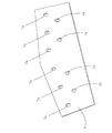
図1において、1は下水処理施設、2は沈殿池、3は覆蓋部材である。
<Constitution>
In FIG. 1, 1 is a sewage treatment facility, 2 is a sedimentation basin, and 3 is a cover member.
沈殿池2は上面視形状が長方形状の開口部2aを有しており、開口部2aの周壁及び周囲の床はコンクリートによって形成されている。
The
覆蓋部材3は、開口部2aの周縁のうち沈殿池2の幅手方向両側の側縁部2b,2b間に複数架け渡されている。
A plurality of
本実施例の沈殿池2の開口部2aは、幅が13.5mあり、10m以上のスパンを有している。
The opening 2a of the
個々の覆蓋部材3は沈殿池2の幅手方向に長く、開口部2aを複数の覆蓋部材3で覆った際には、全体として屋根型を呈している。
Each
図2に示すように、開口部2aを覆っている覆蓋部材3には、端末用覆蓋部材3aと、中間用覆蓋部材3bと、点検口付覆蓋部材3cとの3つのタイプが用いられている。
As shown in FIG. 2, the
端末用覆蓋部材3aは沈殿池2の長手方向両端位置で用いられ、中間用覆蓋部材3bと点検口付覆蓋部材3cとは沈殿池2の長手方向両端位置以外で用いられる。
The
〈端末用覆蓋部材3aの構成〉
端末用覆蓋部材3aは中間用覆蓋部材3bと側板3d,3dとによって構成されており、中間用覆蓋部材3bの幅手方向一方の側部に側板3d,3dが貼り付けられ、一方の側部が塞がれている。
<Configuration of
The
点検口付覆蓋部材3cは、中間用覆蓋部材3bの長手方向一方の端部の上面に開閉可能な点検口3eが設けられている。
The
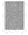
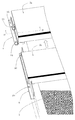
図3に示すように、沈殿池2の幅手方向両側の側縁部2b,2bには、沈殿池2の四隅付近に4つの固定用金具4がそれぞれ取り付けられ、沈殿池2の長手方向に沿って両側に2つのレール用金具5がそれぞれ取り付けられている。
As shown in FIG. 3, four fixing
図4(a)に示すように、固定用金具4は、横板部4aと、縦板部4bと、固定フランジ部4cとによって構成されている。
As shown in FIG. 4A, the fixing
横板部4aと縦板部4bと固定フランジ部4cとは略長方形状を呈しており、横板部4aと縦板部4bとは同一の長さを有している。
The
縦板部4bの幅手方向一端縁からは垂直に横板部4aが延びており、縦板部4bの幅手方向他端縁中央からは垂直に横板部4aと同じ側に固定フランジ部4cが延びている。
A
横板部4aの長手方向両端付近には、それぞれボルト穴4d,4dが設けられ、固定フランジ部4cの略中央には、ボルト穴4eが設けられている。
図4(b)に示すように、レール用金具5は、横板部5aと、縦板部5bとによって構成されている。
As shown in FIG.4 (b), the
横板部5aと縦板部5bとは長尺の長方形状を呈しており、横板部4aと縦板部5bとは同一の長さを有している。
The
横板部5aの幅手方向一端縁からは垂直に縦板部5bが延びており、横板部5aには複数のボルト穴5c,…が等間隔に設けられている。
A
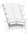
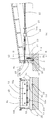
図5に示すように、中間用覆蓋部材3bは、平面視形状が略長方形状の2枚の覆蓋パネル6と、4つの連結金具7と、20個のボルト8と、20個のナット9とによって構成されている。
As shown in FIG. 5, the
本実施例の覆蓋パネル6は長さが約7m、幅が約1m、高さが約0.25mである。
The
覆蓋パネル6は、予め、工場内で製造される。
The
図5または図6に示すように、覆蓋パネル6は、天板6aと、側板6bと、蓋板6cと、梁板6dと、補強板6eと、スペーサー板6f,6gと、座板6hと、ゴム製のパッキング材6i,6jとによって構成されている。
As shown in FIG. 5 or FIG. 6, the
側板6b,6bの連結端部側には、それぞれ5つの連結用のボルト穴6kが設けられている。
Five connecting
符号6a〜6hの部材は、すべて後述するFFU板材によって形成されている。
All
FFU(Fiber reinforced Foamed Urethane)とは繊維強化発泡ウレタンのことであり、本実施例のFFU板材では、繊維にガラス長繊維を用いている。 FFU (Fiber reinforced foamed urethane) is a fiber reinforced urethane foam, and the FFU plate material of the present embodiment uses long glass fibers for the fibers.
束ねたガラス長繊維をほぐしながらにウレタン樹脂を含浸させて発泡させた樹脂素材であり、木材と同程度の比重に成形可能であり、剛性が高く、薬品などに対する耐浸食性に優れた樹脂素材である。 A resin material that is foamed by impregnating urethane resin while loosening the bundled long glass fibers, can be molded to the same specific gravity as wood, has high rigidity, and has excellent erosion resistance against chemicals It is.
FFUは、エポキシ系接着剤との親和性がよく、スクリュウ釘や木ネジなどによって接合することも可能であり、穴開け加工や切断がドリルやノコギリなどによって容易に行うことができる。 FFU has good affinity with epoxy adhesives, and can be joined by screw nails or wood screws. Drilling and cutting can be easily performed by a drill or a saw.
図6に示すように、覆蓋パネル6には、天板6aの裏面側幅手方向両端部付近に、天板6aに垂直にそれぞれ側板6b,6bが取り付けられている。
As shown in FIG. 6,
側板6bと側板6bとの間には、複数の長方形状の梁板6dが天板6aに垂直にハシゴ状に等間隔に取り付けられている。
Between the
梁板6dの裏面側端面に当接した状態で、側板6b,6bの各内側面にそれぞれ補強板6e,6eが取り付けられている。
Reinforcing
覆蓋パネル6の連結側端部は斜めに形成されている。本実施例の覆蓋パネル6では、覆蓋パネル6の連結側端部は、天板6aの法線方向から測って約8°だけ傾いている。
The connection side end of the
一方、覆蓋パネル6の非連結側端部は、図5に示すように、蓋板6cによって塞がれており、裏面側にはコンクリート床の側縁部2bに載る位置に座板6hが取り付けられている。
On the other hand, as shown in FIG. 5, the unconnected side end of the
蓋板6cは、覆蓋パネル6,6同士を連結して、沈殿池2の幅手方向両側の側縁部2b,2bに架け渡した際に、床面に対して垂直になるように、天板6aの法線方向から測って約8°だけ傾いている。
The
なお、FFU板材同士の接合は、エポキシ系接着剤と、スクリュー釘や木ネジとを併用して行われている。 In addition, joining of FFU board | plate materials is performed by using together an epoxy-type adhesive agent, a screw nail, and a wood screw.
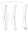
図7に示すように、連結部材7は略ホームベース形状を呈しており、側板6b,6bの各ボルト穴6kに対応した位置に10個のボルト穴7aが設けられている。
As shown in FIG. 7, the connecting
本実施例の中間用覆蓋部材3bや点検口付覆蓋部材3cは、開口部2aの上方で沈殿池2の長手方向に移動できるようになっている。このような可動手段の構成を述べる。
The
図8(a)または図8(b)に示すように、中間用覆蓋部材3bや点検口付覆蓋部材3cの蓋板6cには、キャスター固定用金具10を介して2個のキャスター11,11が取り付けられている。
As shown in FIG. 8 (a) or FIG. 8 (b), two
キャスター固定用金具10は、縦板部10aと、横板部10bとによって構成され、キャスター固定用金具10の長手方向から見た断面形状はL字型を呈している。
The caster fixing metal fitting 10 is composed of a
縦板部10aが蓋板6cにボルトとナットで固定され、横板部10bにキャスター11,11がボルトとナットで取り付けられている。
The
このキャスター11の車輪部11aは周方向に溝が設けられたプーリー様の形状を呈しており、レール用金具5の縦板部5b上に車輪部11aが載っている際に、車輪部11aが縦板部5bの上端縁から脱落しないようになっている。
The
キャスター11の取り付け位置の両側の側板6b及び補強板6eには、レール用金具5上にキャスター11を載せる際に、レール用金具5の縦板部5bと側板6b及び補強板6eとが干渉しないように切欠部6lが形成されている。
When the
車輪部11aの回転面が蓋板6cに平行になるように固定されているので、中間用覆蓋部材3bや点検口付覆蓋部材3cは、これらの幅手方向に移動可能になっている。
Since the rotation surface of the
覆蓋部材3は張架手段を有している。この張架手段の構成を述べる。
The
図8(a)に示すように、中間用覆蓋部材3bや点検口付覆蓋部材3cの一方の蓋板6cには略中央に、覆蓋部材3の中央側に向けて長尺ボルト12が取り付けられている。
As shown in FIG. 8A, a
この長尺ボルト12には、ターンバックル13を介してアイボルト14が取り付けられており、アイボルト14のリング部14aには、ワイヤー15が通され、ワイヤー15を折り曲げた状態で、シャックル16で固定することによって、アイボルト14にワイヤー15の一方の端部が取り付けられている。
An
ワイヤー15の他方の端部も同様にして、中間用覆蓋部材3bや点検口付覆蓋部材3cの他方の蓋板6cに連結されている。
Similarly, the other end of the
このような張架手段によって両端の蓋板6c,6c間に張力を加える。ターンバックル13を回転させることによって、この張力を調整して部材の撓みなどによる中間用覆蓋部材3bや点検口付覆蓋部材3cの僅かな長さ変化を調整するようになっている。
Tension is applied between the
〈施工方法〉
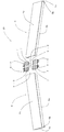
図9(a)または図9(b)に示すように、2枚の覆蓋パネル6,6の連結側端部同士を突き合わせた状態で、突き合わせ位置で、覆蓋パネル6の側板6bの両側面に連結部材7,7をそれぞれ両側から当接させて、側板6bのボルト穴6kと、連結部材7のボルト穴7aの位置を合わせ、ボルト8を挿通し、ボルト8とナット9とによって側板6bの両側から締め付けて覆蓋パネル6,6同士を連結する。
<Construction method>
As shown in FIG. 9 (a) or 9 (b), the connecting side end portions of the two
図10または図11に示すように、沈殿池2の両側縁部2bに固定用金具4を取り付ける。
As shown in FIG. 10 or FIG. 11, fixing
固定用金具4には予め、ボルト穴4d,4dが設けられており、これらのボルト穴4d,4dの位置に対応して、沈殿池2の側縁部2bの上端部にコンクリートドリルで穴を開け、アンカー部材17を挿入する。
The fixing
固定用金具4をアンカー部材17が埋め込まれたコンクリート床上に載せて、ボルト18をアンカー部材17に挿入して締め付ける。
The fixing
図10または図11に示すように、沈殿池2の側縁部2bにレール用金物5を取り付ける。
As shown in FIG. 10 or FIG. 11, the
レール用金物5のボルト穴5c,…の位置に対応して、沈殿池2の側縁部2bのコンクリート床上にコンクリートドリルで穴を開け、アンカー部材19を挿入する。
Corresponding to the positions of the bolt holes 5c of the
そして、レール用金物5をアンカー部材19が埋め込まれたコンクリート床上に載せて、ボルト20をアンカー部材19に挿入して締め付ける。
Then, the
まず、端末用覆蓋部材3aの側板3d側を沈殿池2の長手方向外側に向けるようにして、端末用覆蓋部材3aをクレーンなどで吊して、沈殿池2の長手方向の一方の端部側に架け渡して設置する。
First, the
この際、沈殿池2の幅手方向両側部に予め取り付けられていた一方の固定用金具4の縦板部4bと、他方の固定用金具4の縦板部4bとの間に、端末用覆蓋部材3a両側端面を嵌合させる。
At this time, a terminal cover is provided between the
端末用覆蓋部材3aを設置した後に、図10または図11に示すように、固定用L字型金具21と固定用金具4とをボルトとナットとで連結する。
After installing the
次に、中間用覆蓋部材3bをクレーンなどで吊して、図10に示すように、沈殿池2の幅手方向両側部に予め取り付けられたレール用金物5の縦板5b上に中間用覆蓋部材3bの車輪部11aを載せて、中間用覆蓋部材3bを沈殿池2に架け渡す。
Next, the
この際、中間用覆蓋部材3bの撓みによって車輪部11aがレール用金物5にうまく載らないときには、ターンバックル13を回して、中間用覆蓋部材3bの長手方向の長さを微調整して、車輪部11aがレール用金物5に載るように調整する。
At this time, when the
車輪部11aがレール用金物5に載り中間用覆蓋部材3bが架け渡されたら、中間用覆蓋部材3bをレール用金物5上で沈殿池2の長手方向に滑らせて、既に設置されている端末用覆蓋部材3aに隣接させて設置する。
When the
そして、別の中間用覆蓋部材3bを次々にレール用金物5上に載せて架け渡しては、レール用金物5上を滑らせて、既に設置されている中間用覆蓋部材3bに隣接させて設置する。
Then, another
必要に応じて、点検口付覆蓋部材3cを同様にして設置する。
If necessary, the
このような作業を繰り返して、沈殿池2の長手方向の他方の端部側に達したら、端末用覆蓋部材3aを側板3d側を沈殿池2の長手方向外側に向けて設置する。
When such an operation is repeated and the other end side in the longitudinal direction of the settling
そして、設置された端末用覆蓋部材3aの長手方向両端部を沈殿池2の両側の側縁部2b,2bに、それぞれ固定用金具4,4を取り付ける。
And the
固定用金具4の固定用フランジ部4cを固定用L字型21を介して端末用覆蓋部材3aの蓋板6cに固定して設置作業を完了する。
The fixing
《連結部材の変形例》
連結部材7の変形例として、例えば、図12に示すような連結部材7Aを用いることができる。
<Modification of connecting member>
As a modification of the connecting
連結部材7Aは、連結板部7Aaと、2つの嵌合枠体7Ab,7Abとによって構成されている。
The connecting
嵌合枠体7Abは、ウエブ部7Acと、ウエブ部7Acの上下端縁から垂直に延びる一対のフランジ部7Ad,7Aeとによって構成されている。 The fitting frame body 7Ab includes a web portion 7Ac and a pair of flange portions 7Ad and 7Ae extending vertically from the upper and lower end edges of the web portion 7Ac.
フランジ部7Ad,7Aeには、それぞれボルト穴7Afが設けられている。 Bolt holes 7Af are provided in the flange portions 7Ad and 7Ae, respectively.
連結部材7Aによって連結される覆蓋パネルは、連結側端部の構成が覆蓋パネル6とは異なる覆蓋パネル6Aが用いられる。
As the cover panel connected by the connecting
ここでは、覆蓋パネル6と異なる部分だけを述べる。
Here, only the parts different from the
図13に示すように、側板6bの接合側端部6Abの板厚が、側板6bの他の部分より厚くなっている。
As shown in FIG. 13, the thickness of the joining side end 6Ab of the
接合側端部6Abには、天板6aに垂直に長孔6Akが設けられている。
A long hole 6Ak is provided in the joining side end 6Ab perpendicularly to the
天板6aの端部には、接合側端部6Abの外側端面が面一になるように、切欠きが設けられている。
A notch is provided at the end of the
図14に示すように、覆蓋パネル6A,6Aの連結側端部同士を突き合わせた状態で、連結部材7Aの一対の嵌合枠体7Ab,7Abを覆蓋パネル6A,6Aの接合側端部6Abに嵌め込み、覆蓋パネル6Aの長孔6Akと、フランジ部7Ad,7Aeのボルト穴7Af,7fの位置を合わせた状態で、長尺ボルト22を挿通し、長尺ボルト22とナット23とによって接合側端部6Abを締め付ける。
As shown in FIG. 14, the pair of fitting frames 7Ab and 7Ab of the connecting
〈作用効果〉
覆蓋パネル6は予め工場で製造されており、設置現場である下水処理場1では連結部材7によって連結するだけなので、覆蓋部材3の組み立てが容易に行える。
<Function and effect>
Since the
そして、覆蓋部材3自体は10m以上のスパンを有しているが、組み立てる前の覆蓋パネル6は、約半分のスパンなので、工場から設置現場への搬送が容易に行える。
The
また、両端の端末用覆蓋部材3aが固定用金具4によって、沈殿池2の側縁部2bに固定されるので、覆蓋部材3を安定して設置することができる。
Moreover, since the
特に強風地域では、全ての覆蓋部材3を固定用金具4によって固定すれば、覆蓋部材3が飛ばされることがない。
In particular, in the strong wind region, if all the
更に、中間用覆蓋部材3bや点検口付覆蓋部材3cは可動手段を有しているので、設置施工をスムーズに行うことができる。
Furthermore, since the
そして、中間用覆蓋部材3bや点検口付覆蓋部材3cは張架手段を有しているので、設置の際の撓みによる長さ変化を吸収することができ、設置施工が行い易い。
And since the
また、覆蓋部材3の両側部に、パッキング材6i,6jが貼設されているので、隣接する覆蓋部材3同士で、これらのパッキング材6i,6jが密着して隙間を塞ぐので、沈殿池2からの臭気の漏れを軽減できる。
Moreover, since the
更に、端末用覆蓋部材3aは、側板3dによって側部を塞いでいるので、沈殿池2からの臭気の漏れを軽減できる。
Furthermore, since the
そして、点検口付覆蓋部材3cには、点検口3eが取り付けられているので、点検口3eから沈殿池2内部を覗いて容易に点検できる。
And since the
また、開口部2aの全体を複数の覆蓋部材3で覆った際には、全体として屋根型を呈しているので、雨が降った際に水はけがよい。
Further, when the
更に、覆蓋パネル6は、梁などの補強構造を有しているので、FFU単体の板に比べて強度が強く、10m以上の長スパンの覆蓋部材3が製造可能である。
Furthermore, since the
しかも、覆蓋パネル6はFFUによって形成されているので、耐腐食性があり、腐食性のガスに曝されても長期に渡り使用可能である。
Moreover, since the
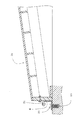
図15に示すように、開口部2aの幅手方向両側にL字型金物24,24をアンカー部材とボルトとによって取り付けて枠を形成し、この枠の内側に複数の覆蓋部材3を嵌め込む。
As shown in FIG. 15, L-shaped
まず、端末用覆蓋部材3aをクレーンで吊して、側板3d側を沈殿池2の長手方向外側に向けて、沈殿池2の長手方向の一方の端部側に架け渡して設置する。
First, the
この際、沈殿池2の幅手方向両側に取り付けられた一方のL字型金物24の内側端面と他方のL字型金物24の内側端面との間に、覆蓋部材3の両側端面を嵌合させる。
At this time, the both end surfaces of the
覆蓋部材3の撓みによって覆蓋部材がL字型金物24,24間に入らないときには、ターンバックル13を回して、覆蓋部材3の長手方向の長さを微調整して、覆蓋部材3がL字型金物24,24間に嵌るように調整する。
When the cover member does not enter between the L-shaped
次に、覆蓋部材3が架け渡されたら、別の覆蓋部材3を既に設置されている覆蓋部材3に隣接させて、次々に架け渡して設置する。
Next, when the
このような作業を繰り返して、沈殿池2の長手方向の他方の端部側に達したら、端末用覆蓋部材3aを側板3d側を沈殿池2の長手方向外側に向けて設置し、設置作業を完了する。
When such an operation is repeated and the other end side in the longitudinal direction of the settling
〈作用効果〉
L字型金物24によって枠体が形成されるので、支持部の施工が容易であるだけでなく、既設の水処理設備であっても、大規模な工事をすることなく覆蓋部材3の設置が可能である。
<Function and effect>
Since the frame is formed by the L-shaped
図16に示すように、開口部2aの幅手方向両側の周壁に、溝部25,25を形成して、この溝部25,25に複数の覆蓋部材3を嵌め込む。
As shown in FIG. 16,
図17に示すように、溝部25,25には、それぞれ補強用L字金具26,26が取り付けられている。
As shown in FIG. 17, L-shaped
まず、端末用覆蓋部材3aをクレーンで吊して、側板3d側を沈殿池2の長手方向外側に向けて、沈殿池2の長手方向の一方の端部側に架け渡して設置する。
First, the
この際、沈殿池2の幅手方向両側部に予め設けられた一方の溝部25の補強用L字金具26の内側端面と他方の溝部25の補強用L字金具26の内側端面との間に、覆蓋部材3の両側端面を嵌合させる。
At this time, between the inner end face of the reinforcing L-shaped metal fitting 26 of the one
覆蓋部材3の撓みによって覆蓋部材3が補強用L字金具26,26間に入らないときには、ターンバックル13を回して、覆蓋部材3の長手方向の長さを微調整して、覆蓋部材3が補強用L字金具26,26間に嵌るように調整する。
When the
次に、覆蓋部材3が架け渡されたら、別の覆蓋部材3を既に設置されている覆蓋部材3に隣接させて、次々に架け渡して設置する。
Next, when the
このような作業を繰り返して、沈殿池2の長手方向の他方の端部側に達したら、端末用覆蓋部材3aを側板3d側を沈殿池2の長手方向外側に向けて設置し、設置作業を完了する。
When such an operation is repeated and the other end side in the longitudinal direction of the settling
〈作用効果〉
開口部2a周囲のコンクリート自体に溝部25,25を形成して、この溝部25,25に複数の覆蓋部材3を嵌め込むので、強固な支持部が得られ、覆蓋部材3を設置した際に、安定した設置が望める。
<Function and effect>
以上、図面を参照して、本発明の最良の実施の形態を詳述してきたが、具体的な構成は、この実施の形態に限らず本発明の要旨を逸脱しない程度の設計的変更は本発明に含まれる。 Although the best embodiment of the present invention has been described in detail with reference to the drawings, the specific configuration is not limited to this embodiment, and design changes that do not depart from the gist of the present invention are not limited to this embodiment. Included in the invention.
なお、実施例では、パッキング材6i,6jはゴム製であるとしたが、必ずしもゴム製である必要はない。例えば、シート状のビニールなどであってもよい。
In the embodiment, the
1 下水処理施設(水処理施設)
2 沈殿池(水槽)
2a 開口部
2b 側縁部(上縁部)
3a 端末用覆蓋部材(覆蓋部材)
3b 中間用覆蓋部材(覆蓋部材)
3c 点検口付覆蓋部材(覆蓋部材)
6,6A 覆蓋パネル(パネル部材)
7,7A 連結部材
6a 天板
6b 側板
6d 梁板
6i,6j パッキング材
3e 点検口
24 L字型金物
1 Sewage treatment facility (water treatment facility)
2 Sedimentation basin (water tank)
3a Terminal cover member (cover member)
3b Intermediate cover member (cover member)
3c Cover member with inspection port (cover member)
6,6A Cover panel (panel member)
7,
Claims (11)
板材によって構成され平面視形状が略長方形状を呈した長尺の2つのパネル部材と、該2つのパネル部材の長手方向一端縁同士を斜めに連結する連結部材とを有し、
前記2つのパネル部材が前記連結部材によって連結されていることを特徴とする覆蓋部材。 The upper part of the water tank installed in the water treatment facility is provided with an opening having a substantially rectangular shape when viewed from above, and a plurality of adjoining the upper edges of the constituent walls constituting the periphery of the opening across the opening And a cover member that covers the upper part of the opening by spanning,
Two long panel members that are configured by a plate material and have a substantially rectangular shape in plan view, and a connecting member that obliquely connects one end edge in the longitudinal direction of the two panel members,
The cover member, wherein the two panel members are connected by the connecting member.
工場で製造された前記パネル部材を前記水処理施設に搬送し、該水処理施設において前記連結部材によって連結し、前記水槽に設置することを特徴とする覆蓋部材の設置方法。 It is the installation method of the cover member described in Claim 1 thru | or 9, Comprising:
A method for installing a cover member, comprising transporting the panel member manufactured in a factory to the water treatment facility, connecting the panel member with the connection member in the water treatment facility, and installing the panel member in the water tank.
前記上縁部に長手方向横断面形状がL字型を呈したL字型金物によって、前記覆蓋部材を嵌合させる枠体を形成し、該枠体間に前記覆蓋部材を並設して設置することを特徴とする覆蓋部材の設置方法。 It is the installation method of the cover member described in Claim 1 thru | or 9, Comprising:
A frame body for fitting the cover member is formed by an L-shaped hardware having an L-shaped longitudinal cross-sectional shape at the upper edge portion, and the cover member is installed in parallel between the frame bodies. An installation method for a cover member, characterized in that:
Priority Applications (1)
| Application Number | Priority Date | Filing Date | Title |
|---|---|---|---|
| JP2006199113A JP4928183B2 (en) | 2006-07-21 | 2006-07-21 | Cover member |
Applications Claiming Priority (1)
| Application Number | Priority Date | Filing Date | Title |
|---|---|---|---|
| JP2006199113A JP4928183B2 (en) | 2006-07-21 | 2006-07-21 | Cover member |
Publications (2)
| Publication Number | Publication Date |
|---|---|
| JP2008024340A true JP2008024340A (en) | 2008-02-07 |
| JP4928183B2 JP4928183B2 (en) | 2012-05-09 |
Family
ID=39115394
Family Applications (1)
| Application Number | Title | Priority Date | Filing Date |
|---|---|---|---|
| JP2006199113A Expired - Fee Related JP4928183B2 (en) | 2006-07-21 | 2006-07-21 | Cover member |
Country Status (1)
| Country | Link |
|---|---|
| JP (1) | JP4928183B2 (en) |
Cited By (2)
| Publication number | Priority date | Publication date | Assignee | Title |
|---|---|---|---|---|
| JP2014079720A (en) * | 2012-10-18 | 2014-05-08 | Sekisui Chem Co Ltd | Cover lid for water treatment facility |
| CN108374480A (en) * | 2018-04-17 | 2018-08-07 | 江苏新纪元环保科技有限公司 | Cover structure is collected in a kind of Nonopaque type fiberglass deodorization for sewage treatment plant |
Citations (8)
| Publication number | Priority date | Publication date | Assignee | Title |
|---|---|---|---|---|
| JPS57173880A (en) * | 1981-04-20 | 1982-10-26 | Oki Electric Ind Co Ltd | Memory for character pattern |
| JPH03125857U (en) * | 1990-03-31 | 1991-12-19 | ||
| JPH10297659A (en) * | 1997-04-23 | 1998-11-10 | Kaidou Kogyo:Kk | Lid receiving structure of container, lid receiving frame constituting the same, and method for forming lid receiving structure of container using the lid receiving frame |
| JP2002002877A (en) * | 2000-06-19 | 2002-01-09 | Sekisui Chem Co Ltd | Reinforcement structure and method of cover |
| JP2002088739A (en) * | 2000-09-19 | 2002-03-27 | Sekisui Chem Co Ltd | Arched lid |
| JP2003012086A (en) * | 2001-06-29 | 2003-01-15 | Takiron Co Ltd | Covering lid |
| JP2004196339A (en) * | 2002-12-18 | 2004-07-15 | Tokyo Metropolis | Cover structure of the upper and lower water tank openings |
| JP2006103796A (en) * | 2004-09-07 | 2006-04-20 | Furukawa Sky Kk | Water tank cover device |
-
2006
- 2006-07-21 JP JP2006199113A patent/JP4928183B2/en not_active Expired - Fee Related
Patent Citations (8)
| Publication number | Priority date | Publication date | Assignee | Title |
|---|---|---|---|---|
| JPS57173880A (en) * | 1981-04-20 | 1982-10-26 | Oki Electric Ind Co Ltd | Memory for character pattern |
| JPH03125857U (en) * | 1990-03-31 | 1991-12-19 | ||
| JPH10297659A (en) * | 1997-04-23 | 1998-11-10 | Kaidou Kogyo:Kk | Lid receiving structure of container, lid receiving frame constituting the same, and method for forming lid receiving structure of container using the lid receiving frame |
| JP2002002877A (en) * | 2000-06-19 | 2002-01-09 | Sekisui Chem Co Ltd | Reinforcement structure and method of cover |
| JP2002088739A (en) * | 2000-09-19 | 2002-03-27 | Sekisui Chem Co Ltd | Arched lid |
| JP2003012086A (en) * | 2001-06-29 | 2003-01-15 | Takiron Co Ltd | Covering lid |
| JP2004196339A (en) * | 2002-12-18 | 2004-07-15 | Tokyo Metropolis | Cover structure of the upper and lower water tank openings |
| JP2006103796A (en) * | 2004-09-07 | 2006-04-20 | Furukawa Sky Kk | Water tank cover device |
Cited By (2)
| Publication number | Priority date | Publication date | Assignee | Title |
|---|---|---|---|---|
| JP2014079720A (en) * | 2012-10-18 | 2014-05-08 | Sekisui Chem Co Ltd | Cover lid for water treatment facility |
| CN108374480A (en) * | 2018-04-17 | 2018-08-07 | 江苏新纪元环保科技有限公司 | Cover structure is collected in a kind of Nonopaque type fiberglass deodorization for sewage treatment plant |
Also Published As
| Publication number | Publication date |
|---|---|
| JP4928183B2 (en) | 2012-05-09 |
Similar Documents
| Publication | Publication Date | Title |
|---|---|---|
| KR101644921B1 (en) | Construction methods of joining two or more container houses along their long sides | |
| JP4928183B2 (en) | Cover member | |
| KR20190073298A (en) | Reinforced structural system for secure seismic performance by reinforcing existing bricks walls | |
| KR20180013048A (en) | FRP Permanent form for water treatment facilities | |
| JP7369165B2 (en) | residential unit | |
| JP4030717B2 (en) | Corrosion-resistant treatment method for concrete frame surface | |
| KR102011310B1 (en) | variable motion type frame assembly for panel having curvature | |
| JPH11247312A (en) | Joint material for glass block assembling and glass block structural body assembled with the same | |
| JP4591867B2 (en) | Glass block wall structure and construction method thereof | |
| JP2010070907A (en) | Dry double wall structure of underground exterior wall | |
| JP2011025968A (en) | Cover | |
| JPH0719590A (en) | Fitting structure of indoor machine for air-conditioning equipment | |
| JP2000303576A (en) | Moisture condensation proof structure | |
| JPH11190135A (en) | Improvement lining construction method for concrete building frame wall face and improvement lining structure | |
| JP7689655B2 (en) | Mobile house, installation method for mobile house, and foundation for mobile house | |
| JP7411773B2 (en) | Installation structure of wooden panels for roofs | |
| KR200290838Y1 (en) | Reinforcement-Plate of Marble for a Structure | |
| JP7244593B2 (en) | residential unit | |
| JP7476127B2 (en) | Beam support structure and beam support method | |
| KR100463025B1 (en) | Reinforcement-Plate of Marble for a Structure | |
| JP2006233579A (en) | Structure basics | |
| JP2003293382A (en) | Method for reinforcing foundation of wooden house | |
| JP2002030671A (en) | Plinth block, sill foundation, and structure and method of joining base to structure body | |
| JP2006214268A (en) | Method of connecting foundation members, columns or beams in a wooden building | |
| JP2003290762A (en) | Arch type lid and method of erection thereof |
Legal Events
| Date | Code | Title | Description |
|---|---|---|---|
| A621 | Written request for application examination |
Free format text: JAPANESE INTERMEDIATE CODE: A621 Effective date: 20090515 |
|
| A977 | Report on retrieval |
Free format text: JAPANESE INTERMEDIATE CODE: A971007 Effective date: 20110712 |
|
| A131 | Notification of reasons for refusal |
Free format text: JAPANESE INTERMEDIATE CODE: A131 Effective date: 20110802 |
|
| A521 | Written amendment |
Free format text: JAPANESE INTERMEDIATE CODE: A523 Effective date: 20110824 |
|
| A131 | Notification of reasons for refusal |
Free format text: JAPANESE INTERMEDIATE CODE: A131 Effective date: 20110927 |
|
| A521 | Written amendment |
Free format text: JAPANESE INTERMEDIATE CODE: A523 Effective date: 20111104 |
|
| A131 | Notification of reasons for refusal |
Free format text: JAPANESE INTERMEDIATE CODE: A131 Effective date: 20111206 |
|
| A521 | Written amendment |
Free format text: JAPANESE INTERMEDIATE CODE: A523 Effective date: 20111214 |
|
| TRDD | Decision of grant or rejection written | ||
| A01 | Written decision to grant a patent or to grant a registration (utility model) |
Free format text: JAPANESE INTERMEDIATE CODE: A01 Effective date: 20120117 |
|
| A01 | Written decision to grant a patent or to grant a registration (utility model) |
Free format text: JAPANESE INTERMEDIATE CODE: A01 |
|
| A61 | First payment of annual fees (during grant procedure) |
Free format text: JAPANESE INTERMEDIATE CODE: A61 Effective date: 20120210 |
|
| FPAY | Renewal fee payment (event date is renewal date of database) |
Free format text: PAYMENT UNTIL: 20150217 Year of fee payment: 3 |
|
| FPAY | Renewal fee payment (event date is renewal date of database) |
Free format text: PAYMENT UNTIL: 20150217 Year of fee payment: 3 |
|
| LAPS | Cancellation because of no payment of annual fees |