JP2008043121A - Curved cable guide - Google Patents
Curved cable guide Download PDFInfo
- Publication number
- JP2008043121A JP2008043121A JP2006216698A JP2006216698A JP2008043121A JP 2008043121 A JP2008043121 A JP 2008043121A JP 2006216698 A JP2006216698 A JP 2006216698A JP 2006216698 A JP2006216698 A JP 2006216698A JP 2008043121 A JP2008043121 A JP 2008043121A
- Authority
- JP
- Japan
- Prior art keywords
- cable
- cylindrical body
- guide
- guide member
- cylinder
- Prior art date
- Legal status (The legal status is an assumption and is not a legal conclusion. Google has not performed a legal analysis and makes no representation as to the accuracy of the status listed.)
- Pending
Links
Images

Landscapes
- Electric Cable Installation (AREA)
- Light Guides In General And Applications Therefor (AREA)
Abstract
【課題】 ケーブルの架設延線作業中でもケーブルが擦れて破損することがなく、軽量かつ簡単な構造で、地上から容易に操作可能であり、現場での作業性を向上したカーブ用ケーブルガイドを提供する。
【解決手段】 ケーブルを挿通する樹脂材料で形成された筒体と、当該筒体に装着される円弧形状のガイド部材と、上記筒体と上記ガイド部材を固定する固定部材と、上記ガイド部材に連結され、上記筒体を所定位置に取り付けるための取付部材とを有するケーブルの架設延線のために用いるカーブ用ケーブルガイドであって、上記筒体は、長手方向に沿って側面が切断された切断部を備え、上記ガイド部材は、上記切断部に沿って装着され、上記筒体内に係止する係止部を備えた。
【選択図】 図1
PROBLEM TO BE SOLVED: To provide a cable guide for a curve which is easy to operate from the ground with a light and simple structure without being damaged by rubbing and damaging the cable even when the cable is installed and extended. To do.
SOLUTION: A cylinder formed of a resin material through which a cable is inserted, an arcuate guide member attached to the cylinder, a fixing member that fixes the cylinder and the guide member, and a guide member A cable guide for curve used for erection and extension of a cable having an attachment member for attaching the cylinder to a predetermined position, the side of the cylinder being cut along the longitudinal direction A cutting portion is provided, and the guide member is provided along the cutting portion and includes a locking portion that locks in the cylindrical body.
[Selection] Figure 1
Description
本発明は、主に光ファイバーケーブル等の架設延線の際に使用するカーブ用ケーブルガイドに関するものである。 The present invention relates to a cable guide for a curve mainly used for installing and extending an optical fiber cable or the like.
ケーブルを所定角度のカーブを描きながら架線する際に使用する多輪式カーブ金車が特許文献1に記載されている。このカーブ金車は、複数のローラに沿ってケーブルを導くものである。しかし、このカーブ金車は、複数のローラや、これを取付けるための部材が必要であり、部品点数が多く、構造が複雑で生産性が悪いものである。また、これらのローラを支持する部材は金属からなるため重量が重く、取扱いに不便である。
さらに、ケーブルを円滑に通過させるため、ローラの中央部は凹形状あるいはV字状のケーブルをガイドするための溝が形成される。しかし、従来のカーブ用ケーブルガイドは重いため、ケーブルの張力方向が変化してもケーブルガイド自体はこれに引っ張られない。すなわち、特許文献1に記載のカーブ金車は、電柱等に吊架されるため、延線ケーブルの延線方向に追従して傾斜する。しかし、金車自体が重いと、追従しない。これは、特に光ケーブルの場合、光ケーブルの重量が軽いため、顕著に現れる。したがって、ケーブルがローラ上を移動して引っ張られるため、ケーブルがローラの溝を通過せずにその外側の端部又はローラ支持部材付近を通過することがある。このため、ローラ端部や支持部材でケーブルが擦れてしまう問題があった。
Further, a groove for guiding a concave or V-shaped cable is formed in the central portion of the roller so that the cable passes smoothly. However, since the conventional cable guide for curves is heavy, the cable guide itself is not pulled by this even if the tension direction of the cable changes. That is, since the curved metal wheel described in
本発明は上記従来技術を考慮したものであって、ケーブルの架設延線作業中でもケーブルが擦れて破損することがなく、軽量かつ簡単な構造で、地上から容易に操作可能であり、現場での作業性を向上したカーブ用ケーブルガイドの提供を目的とするものである。 The present invention is based on the above prior art, and the cable is not rubbed and damaged even during cable installation and extension work. It is light and simple in structure and can be easily operated from the ground. The purpose is to provide a cable guide for curves with improved workability.
前記目的を達成するため、請求項1の発明では、ケーブルを挿通する樹脂材料で形成された筒体と、当該筒体に装着される円弧形状のガイド部材と、上記筒体と上記ガイド部材を固定する固定部材と、上記ガイド部材に連結され、上記筒体を所定位置に取り付けるための取付部材とを有するケーブルの架設延線のために用いるカーブ用ケーブルガイドであって、上記筒体は、長手方向に沿って側面が切断された切断部を備え、上記ガイド部材は、上記切断部に沿って装着され、上記筒体内に係止する係止部を備えたことを特徴とするカーブ用ケーブルガイドを提供する。 In order to achieve the above object, according to the first aspect of the present invention, there is provided a cylinder formed of a resin material through which a cable is inserted, an arc-shaped guide member attached to the cylinder, the cylinder and the guide member. A cable guide for curve used for erection and extension of a cable having a fixing member to be fixed and an attachment member connected to the guide member for attaching the cylinder to a predetermined position, wherein the cylinder is A curve cable comprising: a cutting portion whose side surface is cut along a longitudinal direction; and the guide member is provided along the cutting portion and includes a locking portion for locking in the cylindrical body. Provide a guide.
請求項2の発明では、請求項1の発明において、上記筒体は可撓性を有し、側面が波形状に形成された硬質ポリエチレン管であることを特徴としている。 According to a second aspect of the present invention, in the first aspect of the present invention, the cylindrical body is a rigid polyethylene pipe having flexibility and having a side surface formed in a corrugated shape.
請求項3の発明では、請求項1又は2の発明において、上記ガイド部材は、断面H形状のH形鋼であることを特徴としている。
The invention of
請求弧4の発明では、請求項1〜3のいずれかに記載の発明において、上記ガイド部材の端部には、幅方向に広がった膨出部が備わり、当該膨出部の幅は、上記筒体内を挿通するケーブルの径より大きいことを特徴としている。
According to the invention of
請求項1の発明によれば、筒体が樹脂材料で形成されるので、非常に軽量になり、取り扱い性が向上する。したがって、ケーブルの張力方向に追従して筒体の開口端部がケーブルの引っ張り方向を向くので、常に筒体のカーブに沿って筒体内の所定位置をケーブルが通過するため、誤って所定位置から外れて通過してケーブルが擦れて破損することを防止できる。また、ケーブルの張力方向に追従しなくても、ケーブルを受ける部材が筒体であり、かつ、筒体が樹脂材料であるため、筒体のどこでも受けることができ、ケーブルを傷つけることはない。また、円弧状のガイド部材が筒体の切断部に沿って固定部材により確実に装着されるので、ケーブルガイドのカーブ形状を確実に保持することができる。また、ガイド部材には筒体内に係止する係止部が備わるため、筒体に確実に装着することができる。
According to invention of
また、請求項2の発明によれば、筒体の側面が波形状に形成されるので、ケーブルが通過する際の筒体内壁との接触面積が減少する。したがって、ケーブルが筒体内壁により擦れることを抑制できる。また、筒体を適度な可撓性を備えた硬質ポリエチレン管で形成することにより、架設延線作業に耐えうる十分な強度を備え、取扱い性に非常に優れたカーブ用ケーブルガイドを得ることができる。
According to the invention of
また、請求項3の発明によれば、ガイド部材を断面H形状のH形鋼で形成することにより、H形鋼の下片を用いて筒体に確実に係止することができる。
According to the invention of
また、請求項4の発明によれば、ガイド部材の端部には、膨出部が備わり、当該膨出部の幅は、上記筒体内を挿通するケーブルの径より大きいため、筒体をガイド部材に沿って引き抜く際に、膨出部が筒体の切断部を広げながら引き抜かれるため、この広がった部分からケーブルを取り出すことができ、ケーブルが傷つくことを防止できる。
According to the invention of
本発明は、ケーブルを挿通する樹脂材料で形成された筒体と、当該筒体に装着される円弧形状のガイド部材と、上記筒体と上記ガイド部材を固定する固定部材と、上記ガイド部材に連結され、上記筒体を所定位置に取り付けるための取り付け部材とを有するケーブルの架設延線のために用いるカーブ用ケーブルガイドであって、上記筒体は、長手方向に沿って側面が切断された切断部を備え、上記ガイド部材は、上記切断部に沿って装着され、上記筒体内に係止する係止部を備えたことを特徴とするカーブ用ケーブルガイドである。 The present invention provides a cylindrical body formed of a resin material through which a cable is inserted, an arc-shaped guide member attached to the cylindrical body, a fixing member that fixes the cylindrical body and the guide member, and the guide member. A cable guide for curve used for erection and extension of a cable having a connecting member for attaching the cylindrical body to a predetermined position, the cylindrical body having a side surface cut along the longitudinal direction It is a cable guide for a curve provided with the cutting part, The said guide member was equipped along the said cutting part, and was provided with the latching | locking part latched in the said cylinder.
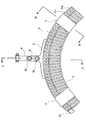
図1は本発明に係るカーブ用ケーブルガイドの概略構成図であり、図2(A)は取付金具の上面図、(B)は図1のA−A断面図である。また、図3は図1のB−B断面図である。なお、図2では図1に示されないガイド用ケーブルガイドに取付金具を取り付けた状態を示す。 FIG. 1 is a schematic configuration diagram of a curve cable guide according to the present invention, FIG. 2A is a top view of a mounting bracket, and FIG. 1B is a cross-sectional view taken along line AA of FIG. 3 is a cross-sectional view taken along the line BB in FIG. FIG. 2 shows a state in which the mounting bracket is attached to a guide cable guide not shown in FIG.
図示したように、本発明に係るカーブ用ケーブルガイド1は、筒体2、ガイド部材3、固定部材4、及び取付部材5で構成される。筒体2は両端部が貫通する円筒体であり、長手方向に沿ってその側面が切断され、切断部6が形成される。ガイド部材3は、断面H形状のH形鋼であり、下片3a、中片3b、上片3cで構成される。ガイド部材3は円弧形状であり、切断部6で中片3bを挟持するように筒体2に装着される。固定部材4は、この筒体2及びガイド部材3の外側から両者を固定する。取付部材5はガイド部材3の中央部上側に備わる。
As shown in the drawing, the
筒体2は、樹脂材料からなる。したがって、従来の金属製のものに比べ、軽量であり、取り扱い性が向上する。また、筒体2は軟質又は硬質のいずれの樹脂材料であっても、所定の可撓性を備えれば、ガイド部材3により円弧形状を形成することができるが、予め筒体2自体を湾曲させて形成してもよい。なお、硬質樹脂材料であれば、カーブ形状を確実に保持できるので好ましい。特に、硬質ポリエチレン管からなるエフレックス(登録商標)を用いれば、後述するガイド部材3が切断部6から外れることを抑制でき、架設延線作業に耐えうる十分な強度を備え、取扱い性に非常に優れているため好ましい。また、筒体2の側面は波形状であるため、ケーブルが通過する際の筒体内壁との接触面積が減少し、ケーブルが筒体内壁により擦れることを抑制できる。また、ケーブルを案内するためのローラを必要としないので、部品点数が減少し、構造が簡単で生産性が向上する。
The
ガイド部材3は、上述したように、筒体2の切断部6に沿って装着される。架設延線作業中は、上方向、すなわち上片3cに備わる取付部材5の方向に引っ張られ、一方筒体2はケーブルの延線張力によって下方に引っ張られるため、下片3aが筒体2の内壁の上側に係止する係止部となり、ガイド部材3は確実に筒体2に係止される。なお、ガイド部材3は、筒体2の内壁に係止して切断部6から抜けない断面構造の係止部を備えていれば、H形鋼に限られるものではない。ガイド部材3の端部には、円柱部材21が溶着されている。この円柱部材21の作用については、後述する。
As described above, the
固定部材4は、雄雌両用の面ファスナーであり、筒体2とガイド部材3を外側から覆って両者を固定する。筒体2とガイド部材3は、複数個所(図では2箇所)で固定部材4により固定される。固定部材4は、一方の端部をガイド部材3の上片3cにネジ7で固定される。この固定部材4は、面ファスナーに限らず、筒体2とガイド部材を把持できるものであればどのような部材を用いてもよい。さらに、当該固定部材4は、ガイド部材3にその一端を固定しているが、必ずしもガイド部材3に固定していなくてもよい。
The
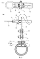
取付部材5には、ボルト10により、リンク片8を介してリンク片9が取付けられる。リンク片9にはフック12が取付けられる。ケーブルの架設延線作業は、このフック12をメッセンジャーワイヤー等に引っ掛けて行われる。フック12の側面には、ボルト11を支点に回動可能なフックアーム13が取付けられる。このフックアーム13は、フック12の開口部を閉鎖自在である。また、フックアーム13は一方の端部に吊り環14を備える。吊り環14とフック12はバネ部材15を介して連結される。このバネ部材15の付勢により、フック12が開放したままになることを常時防止できる。これにより、上方に架設されているメッセンジャーワイヤー16にフック12を引っ掛けた状態で、誤ってメッセンジャーワイヤー16からフック12が外れることを防止できる。なお、図では上述したメッセンジャーワイヤー16に取付ける構造を示したが、本発明の取付部材5は、これに限定されるものではない。また、カーブ用ケーブルガイド1が取付けられるのは、メッセンジャーワイヤー16に限らず、電柱自体等でもよい。
A
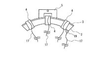
図4は本発明に係る別のカーブ用ケーブルガイドの概略構成図である。
図示したように、取付部材5をコ字状にすることにより、筒体2とガイド部材(図示省略)を中央部で固定部材4により固定できる。筒体2の端部、及び固定部材4にはロープ等の紐部材17が取付けられる。この紐部材17により、上方のメッセンジャーワイヤーに吊り下げられている状態でも、地上から固定部材4を外すことができ、さらに、筒体2をガイド部材3に沿って引き抜くことができる。紐部材17は、例えば図示したように、リング19を介して筒体2に固定される。その他の構成、作用、効果は図1と同様である。
FIG. 4 is a schematic configuration diagram of another curve cable guide according to the present invention.
As illustrated, the
上述したカーブ用ケーブルガイドを用いて架設延線作業をする場合、以下のような手順となる。
延線すべきケーブルを、予め筒体2内に通す。このとき、筒体2の端部から挿通してもよいが、切断部6から入れ込めば、ケーブルが長いときにケーブルの途中部分を入れられるので便利である。次に、ガイド部材3を切断部6に沿って筒体2に装着する。次に、固定部材4により、筒体2とガイド部材3の外側から両者を固定する。
The following procedure is used when performing the construction and extension work using the above-described curve cable guide.
The cable to be extended is passed through the
この後、カーブ用ケーブルガイド1を上方に架設されたメッセンジャーワイヤーに吊り下げる。これは、架設メッセンジャーワイヤーに届く程度の長さを持つ竿部材(図示省略)の先端に吊り環14を引っ掛け、これを持ち上げる。すると、吊り環14が上方に上がるため、バネ部材15の力に抗してフックアーム13が上がり、フック12の開口部が開放する。この開放したフック12を架設メッセンジャーワイヤーに引っ掛け、竿部材を吊り環14から外すと、バネ部材15により吊り環14が下がり、フック12がフックアーム13により閉じられる。これにより、カーブ用ケーブルガイド1は上方の架設メッセンジャーワイヤーに吊り下げられる。
Thereafter, the
この後、ケーブルの架設延線作業を行う。このとき、筒体2内をケーブルが通過するが、筒体2は軽量であるため、ケーブルの張力方向に追従して自在に動く。したがって、筒体2の開口端部もケーブルの引っ張り方向を向くので、常に筒体のカーブに沿って筒体内の所定位置をケーブルが通過する。また、ケーブルの延線方向に筒体が追従して傾斜しなくても、ケーブルは筒体内の任意箇所を通過してケーブルが擦れて破損することを防止できる。また、誤って所定位置から外れて通過しても、筒体2が樹脂材料であるため、ケーブルを傷つけることはない。
After this, cable extension work is performed. At this time, the cable passes through the
架設延線作業が終了すると、固定部材4を取り外す。この後、筒体2をガイド部材3から取り外す。このとき、上述した紐部材17を用いて固定部材4及び筒体2を地上から取り外す。さらに、延線したケーブルを切断部6を介して筒体2内から取り外す。なお、上方で取り外し作業をしてもよい。次に、上記竿部材により吊り環14を引き上げてフックアームを上げ、横に引っ張ってフック12を解放して、取付部材5とともにガイド部材3をメッセンジャーワイヤーから取り外す。これにより、延線したケーブルのみを上方に残し、カーブ用ケーブルガイド1は回収できる。この作業は、すべて地上で容易に行うことができるため、取り扱い性に優れ、作業性が向上する。
When the construction extension work is finished, the fixing
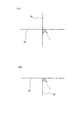
図5は、本発明に係るカーブ用ケーブルガイドが適用される例を示す概略図である。また、図6は、本発明に係るカーブ用ケーブルガイドが適用される別の例を示す概略図である。
図5(A)は、ケーブル20を電柱18の下方に降ろすときを示し、図5(B)は、ケーブル20に高低差をつけたときを示す。また、図5(C)は上面図であり、電柱18に沿ってケーブル20を曲げたときを示す。いずれの場合においても、ケーブル20がカーブを描く部位にカーブ用ケーブルガイド1を設ける。また、図6(A)は、メッセンジャーワイヤー16が十文字状に交差している場合にケーブルガイド1を取付けた状態を示し、図6(B)は、メッセンジャーワイヤー16がT字状に形成されている場合にケーブルガイド1を取付けた状態を示す。
FIG. 5 is a schematic diagram showing an example in which the cable guide for curves according to the present invention is applied. FIG. 6 is a schematic view showing another example to which the cable guide for curves according to the present invention is applied.
FIG. 5A shows the time when the
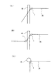
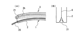
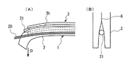
図7及び図8は筒体をガイド部材に沿って引き抜くときの状態を順番に示した概略構成図である。なお、図7、図8において、(A)は断面図であり、(B)は筒体と円柱部材の作用を示す概略構成図である。
図7(A)に示すように、ケーブルガイド1が上方のメッセンジャーワイヤーに取付けられた状態では、筒体2内に光ファイバー等のケーブル20が挿通している。図7(B)に示すように、筒体2の端部の切断部6は、略V字状に切欠かれている。この切欠き部分に、ガイド部材3の中片3bの端部に溶着された円柱部材21が配設される。延線作業が終了すると、図8(A)に示すように、筒体2は下方(矢印D方向)に引っ張られ、ガイド部材3から引き抜かれる。この引き抜き作業は、上述したように、紐部材17(図4参照)により下方から行われる。筒体2が引き抜かれるとともに、図8(B)に示すように、円柱部材21が切断部6を広げるため、この広がった部分からケーブル20が取り出せる。したがって、ケーブル20を切断部6で傷つけることなく筒体2内から取り出すことができる。このような効果を得るために、円柱部材21の径は、ケーブル20の径より大きいことが好ましい。
7 and 8 are schematic configuration diagrams sequentially showing the state when the cylindrical body is pulled out along the guide member. 7 and 8, (A) is a cross-sectional view, and (B) is a schematic configuration diagram showing the operation of the cylindrical body and the columnar member.
As shown in FIG. 7A, in a state where the
なお、この円柱部材21は、円柱状に限らず、ガイド部材3の中片3b端部に備わり、その幅がケーブル20より広い膨出部であれば、どのような形状のものを用いてもよい。
The
本発明は、カーブ用ケーブルガイドとして種々のケーブルに適用できる。 The present invention can be applied to various cables as a cable guide for curves.
1:カーブ用ケーブルガイド、2:筒体、3:ガイド部材、3a:上片、3b:中片、3c:下片、4:固定部材、5:取付部材、6:切断部、7:ネジ、8:リンク片、9:リンク片、10:ボルト、11:ボルト、12:フック、13:フックアーム、14:吊り環、15:バネ部材、16:メッセンジャーワイヤー、17:紐部材、18:電柱、19:リング、20:ケーブル、21:円柱部材
1: cable guide for curve, 2: cylinder, 3: guide member, 3a: upper piece, 3b: middle piece, 3c: lower piece, 4: fixing member, 5: mounting member, 6: cutting part, 7: screw 8: Link piece, 9: Link piece, 10: Bolt, 11: Bolt, 12: Hook, 13: Hook arm, 14: Suspension ring, 15: Spring member, 16: Messenger wire, 17: String member, 18: Telephone pole, 19: ring, 20: cable, 21: cylindrical member
Claims (4)
当該筒体に装着される円弧形状のガイド部材と、
上記筒体と上記ガイド部材を固定する固定部材と、
上記ガイド部材に連結され、上記筒体を所定位置に取り付けるための取付部材とを有するケーブルの架設延線のために用いるカーブ用ケーブルガイドであって、
上記筒体は、長手方向に沿って側面が切断された切断部を備え、
上記ガイド部材は、上記切断部に沿って装着され、上記筒体内に係止する係止部を備えたことを特徴とするカーブ用ケーブルガイド。 A cylinder formed of a resin material that passes through the cable;
An arc-shaped guide member mounted on the cylinder;
A fixing member for fixing the cylindrical body and the guide member;
A cable guide for a curve that is connected to the guide member and is used for extending a cable having a mounting member for mounting the cylindrical body at a predetermined position;
The cylindrical body includes a cutting portion whose side surface is cut along the longitudinal direction,
The curve cable guide, wherein the guide member includes a locking portion that is mounted along the cutting portion and locks in the cylindrical body.
The end portion of the guide member is provided with a bulging portion that expands in the width direction, and the width of the bulging portion is larger than the diameter of the cable that passes through the cylindrical body. Cable guide for curves described in any
Priority Applications (1)
| Application Number | Priority Date | Filing Date | Title |
|---|---|---|---|
| JP2006216698A JP2008043121A (en) | 2006-08-09 | 2006-08-09 | Curved cable guide |
Applications Claiming Priority (1)
| Application Number | Priority Date | Filing Date | Title |
|---|---|---|---|
| JP2006216698A JP2008043121A (en) | 2006-08-09 | 2006-08-09 | Curved cable guide |
Publications (1)
| Publication Number | Publication Date |
|---|---|
| JP2008043121A true JP2008043121A (en) | 2008-02-21 |
Family
ID=39177517
Family Applications (1)
| Application Number | Title | Priority Date | Filing Date |
|---|---|---|---|
| JP2006216698A Pending JP2008043121A (en) | 2006-08-09 | 2006-08-09 | Curved cable guide |
Country Status (1)
| Country | Link |
|---|---|
| JP (1) | JP2008043121A (en) |
Cited By (4)
| Publication number | Priority date | Publication date | Assignee | Title |
|---|---|---|---|---|
| CN109382243A (en) * | 2018-10-29 | 2019-02-26 | 浙江国自机器人技术有限公司 | A kind of ready-package cable spray robot |
| JP2021101245A (en) * | 2015-09-22 | 2021-07-08 | ゴーフォトン・ホールディングス,インコーポレイテッド | Cable wiring device |
| KR20210114724A (en) * | 2020-03-11 | 2021-09-24 | 주식회사 포스코 | Optical jumper cord safe apparatus and electric power system using the same |
| CN121663376A (en) * | 2026-02-05 | 2026-03-13 | 陕昆缆电缆制造(集团)有限公司 | An integrated laying and protection system for optoelectronic cables in complex working conditions |
Citations (6)
| Publication number | Priority date | Publication date | Assignee | Title |
|---|---|---|---|---|
| JPS612713U (en) * | 1984-06-09 | 1986-01-09 | 住友電気工業株式会社 | Cable retraction jig |
| JPS63109507U (en) * | 1986-12-26 | 1988-07-14 | ||
| JPH0279114U (en) * | 1988-12-05 | 1990-06-18 | ||
| JPH0479713A (en) * | 1990-07-20 | 1992-03-13 | Nkk Corp | How to lay cables inside buried pipes |
| JPH0431766Y2 (en) * | 1987-07-29 | 1992-07-30 | ||
| JPH10164718A (en) * | 1996-11-26 | 1998-06-19 | Nishi Nippon Electric Wire & Cable Co Ltd | Pipe remover |
-
2006
- 2006-08-09 JP JP2006216698A patent/JP2008043121A/en active Pending
Patent Citations (6)
| Publication number | Priority date | Publication date | Assignee | Title |
|---|---|---|---|---|
| JPS612713U (en) * | 1984-06-09 | 1986-01-09 | 住友電気工業株式会社 | Cable retraction jig |
| JPS63109507U (en) * | 1986-12-26 | 1988-07-14 | ||
| JPH0431766Y2 (en) * | 1987-07-29 | 1992-07-30 | ||
| JPH0279114U (en) * | 1988-12-05 | 1990-06-18 | ||
| JPH0479713A (en) * | 1990-07-20 | 1992-03-13 | Nkk Corp | How to lay cables inside buried pipes |
| JPH10164718A (en) * | 1996-11-26 | 1998-06-19 | Nishi Nippon Electric Wire & Cable Co Ltd | Pipe remover |
Cited By (6)
| Publication number | Priority date | Publication date | Assignee | Title |
|---|---|---|---|---|
| JP2021101245A (en) * | 2015-09-22 | 2021-07-08 | ゴーフォトン・ホールディングス,インコーポレイテッド | Cable wiring device |
| JP7189982B2 (en) | 2015-09-22 | 2022-12-14 | ゴーフォトン・ホールディングス,インコーポレイテッド | cable wiring device |
| CN109382243A (en) * | 2018-10-29 | 2019-02-26 | 浙江国自机器人技术有限公司 | A kind of ready-package cable spray robot |
| KR20210114724A (en) * | 2020-03-11 | 2021-09-24 | 주식회사 포스코 | Optical jumper cord safe apparatus and electric power system using the same |
| KR102467191B1 (en) * | 2020-03-11 | 2022-11-16 | 주식회사 포스코 | Optical jumper cord safe apparatus and electric power system using the same |
| CN121663376A (en) * | 2026-02-05 | 2026-03-13 | 陕昆缆电缆制造(集团)有限公司 | An integrated laying and protection system for optoelectronic cables in complex working conditions |
Similar Documents
| Publication | Publication Date | Title |
|---|---|---|
| CN212687172U (en) | A new type of cable pay-off rack | |
| JP2009118561A (en) | Insulator bind | |
| JP2008043121A (en) | Curved cable guide | |
| JP7678666B2 (en) | Riser pipe installation method, guide pipe and hanging clamp | |
| JP5559092B2 (en) | Reconstruction method for power pole installation line and retooling tool used in such construction method | |
| JP2008271684A (en) | High-voltage cable support, stringing structure for high-voltage cable, and method of stringing high-voltage cable | |
| JPH1094125A (en) | Support device for sheave device | |
| JP7743978B2 (en) | Construction pole fittings | |
| JP5419748B2 (en) | Safety net clamp and safety net extension method using this clamp | |
| JP5060867B2 (en) | Fixing method of pile driver and hoisting rope | |
| JP3730909B2 (en) | New and old wire bundling construction method and hanger removal device used for it | |
| CN219587238U (en) | Mobilizable steel strand wires fixing device | |
| JP5759944B2 (en) | Floating fish anchor collection method and collection basket used in the collection method | |
| JP3120060U (en) | Removable fixing bracket | |
| JP2005351055A (en) | Anchor device installation method, anchor and anchor device | |
| JP2011061879A (en) | Technique and tool for leading in bent portion of cable | |
| CN221663452U (en) | C-shaped hook for front pivot guy rope hanging basket | |
| JP4062131B2 (en) | Method of joining steel pipes with mechanical joints and steel pipes with mechanical joints used therefor | |
| JPH0932351A (en) | Pole for erecting column | |
| CN210461928U (en) | Lifting aid for flexible umbilical installation | |
| CN215974631U (en) | Laying device for crane sling cable and crane | |
| JP4865927B1 (en) | Hook locking system | |
| JP2010035379A (en) | Auxiliary protection pipe mounting device and method of mounting protection pipe using the same | |
| JP2002130534A (en) | Piping joint tool | |
| JP4738008B2 (en) | Aerial work platform |
Legal Events
| Date | Code | Title | Description |
|---|---|---|---|
| A621 | Written request for application examination |
Free format text: JAPANESE INTERMEDIATE CODE: A621 Effective date: 20090330 |
|
| A977 | Report on retrieval |
Free format text: JAPANESE INTERMEDIATE CODE: A971007 Effective date: 20091102 |
|
| A131 | Notification of reasons for refusal |
Free format text: JAPANESE INTERMEDIATE CODE: A131 Effective date: 20101102 |
|
| A02 | Decision of refusal |
Free format text: JAPANESE INTERMEDIATE CODE: A02 Effective date: 20110301 |