JP2008143473A - Rear structure of airbag cover - Google Patents
Rear structure of airbag cover Download PDFInfo
- Publication number
- JP2008143473A JP2008143473A JP2006336124A JP2006336124A JP2008143473A JP 2008143473 A JP2008143473 A JP 2008143473A JP 2006336124 A JP2006336124 A JP 2006336124A JP 2006336124 A JP2006336124 A JP 2006336124A JP 2008143473 A JP2008143473 A JP 2008143473A
- Authority
- JP
- Japan
- Prior art keywords
- airbag cover
- airbag
- wiring board
- cover
- flexible wiring
- Prior art date
- Legal status (The legal status is an assumption and is not a legal conclusion. Google has not performed a legal analysis and makes no representation as to the accuracy of the status listed.)
- Pending
Links
Images

Landscapes
- Air Bags (AREA)
Abstract
【課題】エアバッグカバーの背面に発光手段を備える場合に、エアバッグの展開に支障を来さずに、エアバッグカバーの背面の狭いスペースに通電線を無理なく配索できるようにする。
【解決手段】ステアリングホイール10の中央部に、エアバッグ100を覆うエアバッグカバー20が設けられており、そのエアバッグカバーの背面に、エンブレム等の装飾部25またはその周囲を背後から照明する発光手段が設けられたエアバッグカバーの背面構造において、発光手段としてのLED35をフレキシブル配線板30上に実装し、該フレキシブル配線板を、エアバッグカバーに形成された開裂予定ライン21を避けた位置に配置した。
【選択図】図1When a light emitting means is provided on the back surface of an air bag cover, it is possible to reasonably route a conductive wire in a narrow space on the back surface of the air bag cover without hindering the deployment of the air bag.
An airbag cover 20 that covers an airbag 100 is provided at a central portion of a steering wheel 10, and a light emission that illuminates a decorative portion 25 such as an emblem or its surroundings from behind on the back surface of the airbag cover. In the back structure of the air bag cover provided with the means, the LED 35 as the light emitting means is mounted on the flexible wiring board 30, and the flexible wiring board is placed at a position avoiding the planned cleavage line 21 formed on the air bag cover. Arranged.
[Selection] Figure 1
Description
本発明は、自動車のエアバッグカバーの背面に発光手段が配置された場合の配線部材の配索の仕方を工夫したエアバッグカバーの背面構造に関するものである。 The present invention relates to a back surface structure of an air bag cover in which a wiring member is routed when a light emitting means is disposed on the back surface of an air bag cover of an automobile.
例えば、自動車の運転席用のエアバッグ装置は、ステアリングホイールの中央のセンターパッドの位置に装備されている。 For example, an airbag device for a driver's seat of an automobile is installed at a center pad position in the center of a steering wheel.
この種のエアバッグ装置は、折り畳まれて収納されたエアバッグと、車両衝突等の検出信号に応答してエアバッグに膨張用のガスを供給するインフレータと、それらを収納保持するリテーナと、エアバッグの運転者側の面を覆うエアバッグカバーとを主たる構成要素として備え、車両衝突などの非常時に、インフレータから噴射されるガスによりエアバッグを膨張させ、その膨張力によって、センターパッドとして設けられたエアバッグカバーを割り開いて、運転者の前方にエアバッグを膨張展開させる構成になっている。 This type of airbag apparatus includes an airbag that is folded and stored, an inflator that supplies inflation gas to the airbag in response to a detection signal such as a vehicle collision, a retainer that stores and holds the airbag, An airbag cover that covers the driver's surface of the bag is provided as a main component, and in the event of an emergency such as a vehicle collision, the airbag is inflated by the gas injected from the inflator, and is provided as a center pad by the inflating force. The airbag cover is split open to inflate and deploy the airbag in front of the driver.
この場合のエアバッグカバーは、樹脂で一体成形されており、その内面に、エアバッグが膨張した際に開裂してエアバッグの展開を許容するための開裂予定溝(開裂予定ライン)を有している。 In this case, the air bag cover is integrally formed of resin, and has an inner groove on the inner surface of the air bag cover to be opened when the air bag is inflated to allow the air bag to expand (expected opening line). ing.
また、エアバッグカバーは、ステアリングホイールの略中央に最も目立つ存在として設けられたものであるので、その中央には一般に、自動車メーカーの社章や車名を表すエンブレムが設けられている。 Further, since the airbag cover is provided as the most conspicuous presence in the approximate center of the steering wheel, an emblem representing the company emblem and the vehicle name of the automobile manufacturer is generally provided in the center.
また、この種のエンブレムの背面に発光手段を配設し、バックライト照明する技術も提案されている(例えば、特許文献1参照)。
ところで、エアバッグカバーの背面側は、エアバッグ装置の部品類(主にエアバッグ)が場所を占めているため、余分なスペースがほとんどなく、前述のようにエアバッグカバーの背面に発光手段を設けるような場合、エアバッグの展開を妨げないようにすることが必須であることから、通常の被覆電線で配索することは、実際上は大きな困難が伴う。特に被覆電線を使用する場合、その固定ポイントの設定に余分な変更が必要になったりするため、実現が難しいという問題があった。 By the way, since the parts of the airbag device (mainly airbags) occupy the place on the back side of the airbag cover, there is almost no extra space, and the light emitting means is provided on the back side of the airbag cover as described above. In such a case, since it is essential not to prevent the airbag from being hindered, it is practically difficult to route with a normal covered electric wire. In particular, when a covered electric wire is used, there is a problem that it is difficult to realize because an extra change is required in setting the fixed point.
本発明は、上記事情を考慮し、エアバッグの展開に支障を来さずに、エアバッグカバーの背面の狭いスペースに通電線を無理なく配索することができ、しかも、その固定の仕方も自由に選ぶことのできるエアバッグカバーの背面構造を提供することを目的とする。 In consideration of the above circumstances, the present invention can reasonably route the conductive wire in a narrow space on the back surface of the airbag cover without hindering the deployment of the airbag, and also has a fixing method. It is an object to provide a back structure of an airbag cover that can be freely selected.
請求項1の発明は、自動車内の乗員に面する部位に、折り畳まれたエアバッグを覆うと共に該エアバッグの展開膨張時に開裂予定ラインに沿って開裂することで前記エアバッグの展開膨張を許容するエアバッグカバーが設けられており、そのエアバッグカバーの背面に、通電により発光し前記エアバッグカバーを通して光を放つことで、エアバッグカバー上に設けられたエンブレム等の装飾部またはその周囲を背後から照明する発光手段が設けられたエアバッグカバーの背面構造において、前記発光手段をフレキシブル配線板上に実装し、該フレキシブル配線板を、前記エアバッグカバーに形成された前記開裂予定ラインの開裂を妨げないことを特徴としている。 The invention of claim 1 allows the airbag to be deployed and inflated by covering the folded airbag at a portion facing the passenger in the automobile and opening along the planned tear line when the airbag is deployed and inflated. An airbag cover is provided, and the back of the airbag cover emits light when energized and emits light through the airbag cover, so that the decorative portion such as an emblem provided on the airbag cover or its surroundings can be seen. In a back structure of an air bag cover provided with light emitting means for illuminating from behind, the light emitting means is mounted on a flexible wiring board, and the flexible wiring board is cleaved along the planned cleavage line formed on the air bag cover. It is characterized by not disturbing.
請求項2の発明は、請求項1に記載のエアバッグカバーの背面構造であって、前記発光手段がLEDであることを特徴としている。 A second aspect of the invention is the back structure of the airbag cover according to the first aspect, wherein the light emitting means is an LED.
請求項3の発明は、請求項1または2に記載のエアバッグカバーの背面構造であって、 前記エアバッグカバーが、自動車のステアリングホイールの中央部にセンターパッドとして設けられたものであることを特徴としている。 Invention of Claim 3 is the back structure of the airbag cover of Claim 1 or 2, Comprising: The said airbag cover is provided as a center pad in the center part of the steering wheel of a motor vehicle. It is a feature.
請求項4の発明は、請求項1〜3のいずれかに記載のエアバッグカバーの背面構造であって、前記フレキシブル配線板が、前記発光手段を実装した広幅平面部と、該広幅平面部から延長され且つ該広幅平面部よりも幅の狭い帯状の細幅部とからなり、前記広幅平面部が前記エンブレム等の装飾部の背後に正対して配置され、前記細幅部が、前記エアバッグカバーの背面のスペースに沿って取り回された上で、エアバッグカバーの端部に配されたコネクタまで配索されていることを特徴としている。 Invention of Claim 4 is the back structure of the airbag cover in any one of Claims 1-3, Comprising: The said flexible wiring board has mounted from the wide plane part which mounted the said light emission means, and this wide plane part. The narrow flat portion is a strip-shaped narrow portion that is extended and narrower than the wide flat surface portion, the wide flat surface portion is disposed in front of the decorative portion such as the emblem, and the narrow width portion is the airbag. The cable is routed along the space on the back surface of the cover, and is wired up to the connector arranged at the end of the airbag cover.
請求項5の発明は、請求項4に記載のエアバッグカバーの背面構造であって、前記フレキシブル配線板が、フレキシブルプリント回路体で構成されていることを特徴としている。 The invention according to claim 5 is the back structure of the airbag cover according to claim 4, wherein the flexible wiring board is formed of a flexible printed circuit body.
請求項6の発明は、請求項4または5に記載のエアバッグカバーの背面構造であって、前記エアバッグカバーの周縁部に存在する複数のリブに前記細幅部を絡ませることにより、前記フレキシブル配線板をエアバッグカバーに固定したことを特徴としている。
Invention of
請求項7の発明は、請求項1〜6のいずれかに記載のエアバッグカバーの背面構造であって、前記フレキシブル配線板の絶縁フィルムの一部を前記エアバッグカバーに固着することで、前記フレキシブル配線板をエアバッグカバーに固定したことを特徴としている。 Invention of Claim 7 is a back structure of the airbag cover in any one of Claims 1-6, Comprising: A part of insulating film of the flexible wiring board adheres to the airbag cover, The above-mentioned The flexible wiring board is fixed to the airbag cover.
請求項1の発明によれば、発光手段を実装したフレキシブル配線板を、通常の被覆電線の代わりに配線部材として使うことにより、エアバッグカバーの背面の狭いスペースにも、発光手段およびフレキシブル配線板を無理なく容易に配設することができる。また、薄型で柔軟性を有するフレキシブル配線板を、エアバッグカバーに形成した開裂予定ラインを避けた位置に配置している又は、開裂時フレキシブル配線板が破断する構造にするので、エアバッグ展開時に、フレキシブル配線板が邪魔になるおそれがなく、エアバッグカバーにフレキシブル配線板が沿って配索され、エアバッグ展開時にはエアバッグカバーに追従しエアバッグの展開に支障を来さない。また、フレキシブル配線板の使用により、その固定の仕方に自由度が出るため、無用な突起物を設けて配線板を固定する等のエアバッグ破損につながるような手段を講じる必要がなく、安全なエアバッグの展開を保証することができる。 According to the first aspect of the present invention, the flexible wiring board on which the light emitting means is mounted is used as a wiring member instead of a normal covered electric wire, so that the light emitting means and the flexible wiring board can be used in a narrow space on the back surface of the airbag cover. Can be easily arranged without difficulty. In addition, the flexible wiring board that is thin and flexible is arranged at a position that avoids the planned tear line formed on the airbag cover, or the flexible wiring board breaks at the time of tearing. The flexible wiring board is not obstructed, and the flexible wiring board is routed along the airbag cover. When the airbag is deployed, it follows the airbag cover and does not hinder the deployment of the airbag. In addition, the use of flexible wiring boards gives you more flexibility in how to fix them, so there is no need to take measures to prevent damage to the airbag, such as fixing unnecessary wiring protrusions and fixing the wiring boards. The deployment of the airbag can be guaranteed.
請求項2の発明によれば、発光手段として、小型の発光素子であるLEDをフレキシブル配線板上に実装したので、フレキシブル配線板の柔軟性を妨げずに、エアバッグカバーの背後の狭いスペースにLED付きのフレキシブル配線板を無理なく配索することができる。そして、エアバッグカバーの背面の狭いスペースから、エアバッグカバー上に設けられたエンブレム等の装飾部またはその周囲を発光することができる。 According to the second aspect of the present invention, the LED, which is a small light emitting element, is mounted on the flexible wiring board as the light emitting means, so that the flexibility of the flexible wiring board is not hindered and a narrow space behind the airbag cover is provided. Flexible wiring boards with LEDs can be routed without difficulty. Then, from a narrow space on the back surface of the airbag cover, the decoration portion such as an emblem provided on the airbag cover or the periphery thereof can emit light.
請求項3の発明によれば、ステアリングホイールの中央部に配したエアバッグカバーの背面に、発光手段を実装したフレキシブル配線板を配置しているので、運転者を保護するために作動するエアバッグの展開を妨げることなく、発光手段の発する光によって、エアバッグカバー上のエンブレム等の装飾物を夜間でも発光することができる。 According to the invention of claim 3, since the flexible wiring board on which the light emitting means is mounted is disposed on the back surface of the airbag cover disposed in the center portion of the steering wheel, the airbag that operates to protect the driver. Without obstructing the deployment of the embroidery, it is possible to illuminate a decorative object such as an emblem on the airbag cover even at night by the light emitted by the light emitting means.
請求項4の発明によれば、広幅平面部から延長された細幅部を利用して、エアバッグカバーの背面のスペースに沿ってフレキシブル配線板をコネクタまで取り回すので、無理のない形態でフレキシブル配線板をエアバッグカバーの背面で配索することができる。 According to the invention of claim 4, since the flexible wiring board is routed to the connector along the space on the back surface of the airbag cover using the narrow width portion extended from the wide flat surface portion, it is flexible in a reasonable form. The wiring board can be routed behind the airbag cover.
請求項5の発明によれば、フレキシブル配線板をフレキシブルプリント回路体で構成したので、広幅平面部と細幅部を、実際に配索しやすいように自由に形成することができる。 According to the invention of claim 5, since the flexible wiring board is formed of the flexible printed circuit body, the wide flat surface portion and the narrow width portion can be freely formed so as to be actually easy to route.
請求項6の発明によれば、エアバッグカバーの強度確保の上で必要なリブに細幅部を絡ませることで、フレキシブル配線板をエアバッグカバーに固定したので、特別な固定手段をエアバッグカバーの背面に設ける必要がなく、コストアップを避けられる。
According to the invention of
請求項7の発明によれば、絶縁フィルムの一部をエアバッグカバーに固着することで、フレキシブル配線板をエアバッグカバーに固定したので、特別な固定手段を設けず、コスト上昇を避けながら、フレキシブル配線板をエアバッグカバーの背面に安定して配索することができる。 According to the invention of claim 7, since the flexible wiring board is fixed to the airbag cover by fixing a part of the insulating film to the airbag cover, no special fixing means is provided, and cost increase is avoided. The flexible wiring board can be stably routed on the back surface of the airbag cover.
以下、本発明の実施形態を図面を参照して説明する。 Hereinafter, embodiments of the present invention will be described with reference to the drawings.
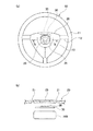
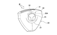
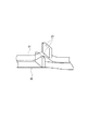
図1の(a)は実施形態の構造を適用したステアリングホイールの正面図、(b)は(a)のIa−Ia矢視断面図、図2はエアバッグカバーの前側から見た斜視図、図3は図2のIII矢視部分の斜視図、図4は図3の適当な箇所に採用されるフレキシブル配線板の固定構造の斜視図である。 1A is a front view of a steering wheel to which the structure of the embodiment is applied, FIG. 1B is a sectional view taken along the arrow Ia-Ia in FIG. 1A, and FIG. 2 is a perspective view seen from the front side of the airbag cover. 3 is a perspective view of a portion taken along the arrow III in FIG. 2, and FIG. 4 is a perspective view of a flexible wiring board fixing structure employed at an appropriate position in FIG.
一般に自動車には、乗員に面する部位、例えば、運転席の場合は、図1に示すようなステアリングホイール10の中央部のセンターパッドの位置に、エアバッグ装置が装備されている。図1(b)ではエアバッグ100のみを図示している。エアバッグ100は、折り畳まれた状態で収容されており、その乗員側の面には、エアバッグ100を覆うエアバッグカバー20がセンターパッドとして設けられている。
In general, an automobile is equipped with an airbag device at a position facing a passenger, for example, in the case of a driver's seat, at a center pad position at the center of the
このエアバッグカバー20は、エアバッグ100の展開膨張時に開裂予定ライン(テアライン)21に沿って開裂することで、エアバッグ100の展開膨張を許容するようになっており、ステアリングホイール10に固定されている。
The
ステアリングホイール10は、リング状のリム11と中心のハブ13とを複数本のスポーク12で接続した構造のものであり、ハブ13の中心部に図示略のステアリングシャフトが固定されることで、ステアリングホイール10とステアリングシャフトとが連結されている。そして、エアバッグ装置はハブ13に装備され、ハブ13の上側にエアバッグカバー20が配設されている。
また、そのエアバッグカバー20の背面側には、通電されることにより発光しエアバッグカバー20を通して光を放つことで、エアバッグカバー20上に設けられたエンブレム等の装飾部25またはその周囲を背後から照明するLED(発光手段)35が配設されている。この場合、エンブレム等の装飾部25またはその周囲が、背後からの光を透過する材料で構成されている。
The
Further, the back surface side of the
LED35はフレキシブル配線板30上に実装されており、そのフレキシブル配線板30は、エアバッグカバー20に形成された開裂予定ライン21を避けた位置に配置又は、開裂時フレキシブル配線板が破断する構造にする。フレキシブル配線板30としては、フレキシブルプリント回路体(FPC)やフレキシブルフラットケーブル(FFC)等を採用できるが、ここでは形状自由度の高い前者が用いられている。
The
図2、図3に示すように、フレキシブル配線板30は、LED35を実装した広幅平面部30Aと、広幅平面部30Aから延長され且つ広幅平面部30Aよりも幅の狭い帯状の細幅部31とからなり、広幅平面部30Aがエンブレム等の装飾部25の背後に正対して配置され、細幅部31が、エアバッグカバー20の背面のスペースに沿って取り回された上で、エアバッグカバー20の端部に配されたコネクタ38まで配索されている。
As shown in FIGS. 2 and 3, the
この場合のフレキシブル配線板30の固定は、例えば、図4に示すように、エアバッグカバー20の周縁部に存在する複数のリブ23に細幅部31を絡ませることにより行われている。また、図3に示すように、フレキシブル配線板30の絶縁フィルムの一部に固定片32を設け、その固定片32を溶着したり接着するなどして、エアバッグカバー20への固定が行われている。
For example, as shown in FIG. 4, the
このように、LED35を実装したフレキシブル配線板30を、通常の被覆電線の代わりに配線部材として使用していることにより、エアバッグカバー20の背面の狭いスペースにも、LED35やフレキシブル配線板30を無理なく容易に配設することができる。
Thus, by using the
また、薄型で柔軟性を有するフレキシブル配線板30を、エアバッグカバー20に形成した開裂予定ライン21を避けた位置に配置又は、開裂時フレキシブル配線板が破断する構造にするので、エアバッグ100の展開時に、エアバッグカバーに追従してフレキシブル配線板も破断するためフレキシブル配線板30が邪魔になるおそれがなく、エアバッグ100の展開に支障を来さない。
Further, since the
また、フレキシブル配線板30の使用により、その固定の仕方に自由度が出るため、無用な突起物を設けて配線板を固定する等のエアバッグ100の破損につながるような手段を講じる必要がなく、安全なエアバッグ100の展開を保証することができる。
Further, since the
また、発光手段として、小型の発光素子であるLED35をフレキシブル配線板30上に実装しているので、フレキシブル配線板30の柔軟性を妨げずに、エアバッグカバー20の背後の狭いスペースにLED35付きのフレキシブル配線板30を無理なく配索することができる。そして、エアバッグカバー20の背面の狭いスペースから、エアバッグカバー20上に設けられたエンブレム等の装飾部25またはその周囲を、発光することができる。
Further, since the
また、この実施形態では、ステアリングホイール10の中央部に配したエアバッグカバー20の背面に、LED35を実装したフレキシブル配線板30を配置しているので、運転者を保護するために作動するエアバッグ100の展開を妨げることなく、LED35の発する光によって、エアバッグカバー20上のエンブレム等の装飾物25を夜間でも発光することができる。
Moreover, in this embodiment, since the
また、この実施形態では、広幅平面部30Aから延長された細幅部31を利用して、エアバッグカバー20の背面のスペースに沿ってフレキシブル配線板30をコネクタ38まで取り回しているので、無理のない形態でフレキシブル配線板30をエアバッグカバー20の背面で配索することができる。
In this embodiment, the
特に、この実施形態では、フレキシブル配線板30をフレキシブルプリント回路体で構成しているので、広幅平面部30Aと細幅部31を、実際に配索しやすいような形状に自由に形成することができる。
In particular, in this embodiment, since the
また、エアバッグカバー20の強度確保の上で必要なリブ23にフレキシブル配線板30の細幅部31を絡ませたり、フレキシブル配線板30の絶縁フィルムの一部をエアバッグカバー20に固着したりすることで、フレキシブル配線板30をエアバッグカバー20に固定しているので、特別な固定手段をエアバッグカバー20の背面に設けることなく、コストアップを避けながら、フレキシブル配線板30をエアバッグカバー20の背面に安定して配索することができる。
Further, the
なお、上記実施形態では、ステアリングホイール10用のエアバッグカバー20の背面構造について説明したが、本発明は、助手席前方部位・ドア・シート・車内壁等に搭載されるエアバッグ装置のエアバッグカバーの背面構造に適用してもよい。
In the above-described embodiment, the rear structure of the
10 ステアリングホイール
20 エアバッグカバー
21 開裂予定ライン
23 リブ
25 エンブレム等の装飾部
30 フレキシブル配線板
30A 広幅平面部
31 細幅部
32 固定片(絶縁フィルムの一部)
35 LED(発光手段)
38 コネクタ
100 エアバッグ
DESCRIPTION OF
35 LED (light emitting means)
38
Claims (7)
前記発光手段をフレキシブル配線板上に実装し、該フレキシブル配線板を、前記エアバッグカバーに形成された前記開裂予定ラインの開裂を妨げないことを特徴とするエアバッグカバーの背面構造。 An airbag cover that covers a folded airbag and allows the airbag to be deployed and inflated by covering the folded airbag along the planned tearing line when the airbag is deployed and inflated is provided at a portion facing the passenger in the automobile. And a light emitting means for illuminating a decorative portion such as an emblem provided on the airbag cover or its surroundings from behind by emitting light through the airbag cover and emitting light through the airbag cover on the back surface of the airbag cover. In the back structure of the provided airbag cover,
A rear structure of an airbag cover, wherein the light emitting means is mounted on a flexible wiring board, and the flexible wiring board does not hinder the tearing of the planned tearing line formed on the airbag cover.
前記発光手段がLEDであることを特徴とするエアバッグカバーの背面構造。 The back structure of the airbag cover according to claim 1,
A back structure of an air bag cover, wherein the light emitting means is an LED.
前記エアバッグカバーが、自動車のステアリングホイールの中央部にセンターパッドとして設けられたものであることを特徴とするエアバッグカバーの背面構造。 The back structure of the airbag cover according to claim 1 or 2,
A back structure of an air bag cover, wherein the air bag cover is provided as a center pad at a central portion of a steering wheel of an automobile.
前記フレキシブル配線板が、前記発光手段を実装した広幅平面部と、該広幅平面部から延長され且つ該広幅平面部よりも幅の狭い帯状の細幅部とからなり、前記広幅平面部が前記エンブレム等の装飾部の背後に正対して配置され、前記細幅部が、前記エアバッグカバーの背面のスペースに沿って取り回された上で、エアバッグカバーの端部に配されたコネクタまで配索されていることを特徴とするエアバッグカバーの背面構造。 The back structure of the airbag cover according to any one of claims 1 to 3,
The flexible wiring board includes a wide flat surface portion on which the light emitting means is mounted, and a strip-shaped narrow portion that extends from the wide flat surface portion and is narrower than the wide flat surface portion, and the wide flat surface portion is the emblem. The narrow portion is arranged along the space on the back surface of the airbag cover, and is arranged up to the connector disposed at the end portion of the airbag cover. The back structure of the airbag cover characterized by being searched.
前記フレキシブル配線板が、フレキシブルプリント回路体で構成されていることを特徴とするエアバッグカバーの背面構造。 The back structure of the airbag cover according to claim 4,
The back structure of an airbag cover, wherein the flexible wiring board is formed of a flexible printed circuit body.
前記エアバッグカバーの周縁部に存在する複数のリブに前記細幅部を絡ませることにより、前記フレキシブル配線板をエアバッグカバーに固定したことを特徴とするエアバッグカバーの背面構造。 The back structure of the airbag cover according to claim 4 or 5,
A back structure of an air bag cover, wherein the flexible wiring board is fixed to the air bag cover by entwining the narrow width portion with a plurality of ribs present on a peripheral edge portion of the air bag cover.
前記フレキシブル配線板の絶縁フィルムの一部を前記エアバッグカバーに固着することで、前記フレキシブル配線板をエアバッグカバーに固定したことを特徴とするエアバッグカバーの背面構造。 The back structure of the airbag cover according to any one of claims 1 to 6,
A back structure of an airbag cover, wherein the flexible wiring board is fixed to the airbag cover by fixing a part of the insulating film of the flexible wiring board to the airbag cover.
Priority Applications (1)
| Application Number | Priority Date | Filing Date | Title |
|---|---|---|---|
| JP2006336124A JP2008143473A (en) | 2006-12-13 | 2006-12-13 | Rear structure of airbag cover |
Applications Claiming Priority (1)
| Application Number | Priority Date | Filing Date | Title |
|---|---|---|---|
| JP2006336124A JP2008143473A (en) | 2006-12-13 | 2006-12-13 | Rear structure of airbag cover |
Publications (1)
| Publication Number | Publication Date |
|---|---|
| JP2008143473A true JP2008143473A (en) | 2008-06-26 |
Family
ID=39604106
Family Applications (1)
| Application Number | Title | Priority Date | Filing Date |
|---|---|---|---|
| JP2006336124A Pending JP2008143473A (en) | 2006-12-13 | 2006-12-13 | Rear structure of airbag cover |
Country Status (1)
| Country | Link |
|---|---|
| JP (1) | JP2008143473A (en) |
Cited By (4)
| Publication number | Priority date | Publication date | Assignee | Title |
|---|---|---|---|---|
| EP4052964A4 (en) * | 2019-10-30 | 2024-01-17 | Autoliv Development AB | Steering wheel assembly |
| KR20240166842A (en) * | 2023-05-18 | 2024-11-26 | 아우토리브 디벨롭먼트 아베 | Airbag cover assembly |
| KR20240168093A (en) * | 2023-05-22 | 2024-11-29 | 아우토리브 디벨롭먼트 아베 | Airbag cover assembly |
| US12434651B1 (en) * | 2024-05-24 | 2025-10-07 | Hyundai Mobis Co., Ltd. | Airbag cover assembly including a lighting module |
Citations (3)
| Publication number | Priority date | Publication date | Assignee | Title |
|---|---|---|---|---|
| JPH106999A (en) * | 1996-06-21 | 1998-01-13 | Yazaki Corp | Steering module |
| JP2003327069A (en) * | 2002-05-13 | 2003-11-19 | Breed Automotive Technology Inc | Air bag cover with plastic badge |
| JP2006168704A (en) * | 2004-11-16 | 2006-06-29 | Mazda Motor Corp | Steering wheel with airbag device |
-
2006
- 2006-12-13 JP JP2006336124A patent/JP2008143473A/en active Pending
Patent Citations (3)
| Publication number | Priority date | Publication date | Assignee | Title |
|---|---|---|---|---|
| JPH106999A (en) * | 1996-06-21 | 1998-01-13 | Yazaki Corp | Steering module |
| JP2003327069A (en) * | 2002-05-13 | 2003-11-19 | Breed Automotive Technology Inc | Air bag cover with plastic badge |
| JP2006168704A (en) * | 2004-11-16 | 2006-06-29 | Mazda Motor Corp | Steering wheel with airbag device |
Cited By (6)
| Publication number | Priority date | Publication date | Assignee | Title |
|---|---|---|---|---|
| EP4052964A4 (en) * | 2019-10-30 | 2024-01-17 | Autoliv Development AB | Steering wheel assembly |
| KR20240166842A (en) * | 2023-05-18 | 2024-11-26 | 아우토리브 디벨롭먼트 아베 | Airbag cover assembly |
| KR102827959B1 (en) | 2023-05-18 | 2025-07-02 | 아우토리브 디벨롭먼트 아베 | Airbag cover assembly |
| KR20240168093A (en) * | 2023-05-22 | 2024-11-29 | 아우토리브 디벨롭먼트 아베 | Airbag cover assembly |
| KR102827955B1 (en) | 2023-05-22 | 2025-07-02 | 아우토리브 디벨롭먼트 아베 | Airbag cover assembly |
| US12434651B1 (en) * | 2024-05-24 | 2025-10-07 | Hyundai Mobis Co., Ltd. | Airbag cover assembly including a lighting module |
Similar Documents
| Publication | Publication Date | Title |
|---|---|---|
| KR102885990B1 (en) | Driver's airbag with emblem | |
| JP4609229B2 (en) | Steering wheel with airbag device | |
| US10988099B2 (en) | Cover body for air-bag device | |
| CN112440891B (en) | Covers for decorative parts and modules | |
| JP5019588B2 (en) | Cover body of airbag device and airbag device | |
| EP2415652B1 (en) | Steering wheel and steering device | |
| US11780399B2 (en) | Emblem assembly in airbag cover | |
| JP2009096450A (en) | Airbag device | |
| US20030209889A1 (en) | Plastic emblem attachment method | |
| KR102846539B1 (en) | Driver air bag apparatus for vehicle with illumination emblem | |
| US20160207489A1 (en) | Touch Sensor and Airbag Cover Integrated Input Device | |
| CN212667317U (en) | Driver side airbag device | |
| US20070052211A1 (en) | Airbag device and covering member thereof | |
| JP2006001326A (en) | Airbag cover and airbag device | |
| JP2008143473A (en) | Rear structure of airbag cover | |
| JP2002137709A (en) | Module cover for air bag device | |
| JP2010132013A (en) | Fixing structure of flexible board and air bag device | |
| KR102807541B1 (en) | Wire guide for airbag | |
| JP4853210B2 (en) | Airbag device | |
| JP3169571U (en) | Flexible substrate fixing structure and airbag device | |
| KR102827959B1 (en) | Airbag cover assembly | |
| US12559122B2 (en) | Steering input with light source | |
| JP4419815B2 (en) | Vehicle lighting device | |
| JP2004130989A (en) | Air bag device | |
| JP4424308B2 (en) | Arrangement structure of functional parts for roof side |
Legal Events
| Date | Code | Title | Description |
|---|---|---|---|
| A621 | Written request for application examination |
Free format text: JAPANESE INTERMEDIATE CODE: A621 Effective date: 20090807 |
|
| A131 | Notification of reasons for refusal |
Free format text: JAPANESE INTERMEDIATE CODE: A131 Effective date: 20110419 |
|
| A977 | Report on retrieval |
Free format text: JAPANESE INTERMEDIATE CODE: A971007 Effective date: 20110421 |
|
| A02 | Decision of refusal |
Free format text: JAPANESE INTERMEDIATE CODE: A02 Effective date: 20111004 |