JP2008196629A - Air spring - Google Patents
Air spring Download PDFInfo
- Publication number
- JP2008196629A JP2008196629A JP2007033534A JP2007033534A JP2008196629A JP 2008196629 A JP2008196629 A JP 2008196629A JP 2007033534 A JP2007033534 A JP 2007033534A JP 2007033534 A JP2007033534 A JP 2007033534A JP 2008196629 A JP2008196629 A JP 2008196629A
- Authority
- JP
- Japan
- Prior art keywords
- orifice
- air
- air spring
- base plate
- air chamber
- Prior art date
- Legal status (The legal status is an assumption and is not a legal conclusion. Google has not performed a legal analysis and makes no representation as to the accuracy of the status listed.)
- Pending
Links
- 230000002093 peripheral effect Effects 0.000 claims description 9
- 238000004891 communication Methods 0.000 description 9
- 238000013016 damping Methods 0.000 description 3
- 238000010586 diagram Methods 0.000 description 3
- 238000004519 manufacturing process Methods 0.000 description 3
- 238000012986 modification Methods 0.000 description 3
- 230000004048 modification Effects 0.000 description 3
- 238000009792 diffusion process Methods 0.000 description 2
- 230000000694 effects Effects 0.000 description 2
- 230000005284 excitation Effects 0.000 description 1
- 230000000149 penetrating effect Effects 0.000 description 1
- 230000001629 suppression Effects 0.000 description 1
Images


Landscapes
- Fluid-Damping Devices (AREA)
Abstract
Description
本発明は、鉄道車両等の振動抑制に使用されて好適な空気バネに関する。 The present invention relates to an air spring that is suitable for use in vibration suppression of railway vehicles and the like.
特許文献1に開示されるように、鉄道車両等の振動を抑制するために空気バネが使用される。この種の空気バネの一従来例としては、図8及び図9に示すものがある。
As disclosed in
図8及び図9において、空気バネ100は、内部の本体側空気室101aに加圧空気が充填され、加圧空気の圧力によって弾力が調整される空気バネ本体101と、この空気バネ本体101の下方に配置され、補助空気室102aを内部に有する補助タンク102と、空気バネ本体101と補助タンク102との間に介在されたゴムバネ部103とを備え、空気バネ本体101と補助タンク102の双方の本体側空気室101aと補助空気室102aが連通路104を介して連通されている。
8 and 9, an
空気バネ本体101は、上下位置に配置された一対のベース板110,111と、この一対のベース板110,111の間を囲むうように固定されたベローズ体112とを備えている。下方のベース板111には、そのセンター位置にハンドリング用ネジ孔113が設けられている。このハンドリング用ネジ孔113に上方から内部に進入させたハンドリング部材(図示せず)をネジ込みで固定し、空気バネの運搬などのハンドリングが容易に行える構造となっている。
The air spring
連通路104は、下方のベース板111に設けられたオリフィス114と、ゴムバネ部103の中心位置を貫通する貫通孔115と、ゴムバネ部103の底面板105より下方に突設されたボス部116とから構成されている。
The
オリフィス114は、下方のベース板111のハンドリング用ネジ孔113の下面部に、つまり、ハンドリング用ネジ孔113と同一位置に設けられている。
The
上記構成において、鉄道車両の振動によって空気バネ本体101内の空気が圧縮(加圧)・膨張(減圧)されると、空気バネ本体101の本体側空気室101aと補助タンク102の補助空気室102a間の差圧によって双方の空気が連通路104を介して流出入する。そして、空気流が連通路104のオリフィス114を通過する際に発生する摩擦や拡散によって減衰力が得られるものである。
In the above configuration, when the air in the air spring
このオリフィス114による減衰効果は、孔面積が小さく、且つ、孔長さが短い方が効果的である。従って、ベース板111のハンドリング用ネジ孔113とオリフィス114を併設する従来の構成は、必然的にオリフィス114の孔長さが短くなるため、減衰効果の点で有効である。又、ハンドリング用ネジ孔113とオリフィス114が同一位置である従来例の構成は、ベース板111の加工性にも優れている。
しかし、オリフィス114の孔長さが短いと、高周波音(いわゆる笛吹き音)が発生することが判明した。近年においては、車両の静寂性要求が高く空気バネ100からの耳障りな高周波音の発生を防止する必要がある。
However, it has been found that when the hole length of the
ここで、オリフィス114の孔形状を工夫することで高周波音の発生を防止することが考えられるが、上記従来例では、オリフィス114がハンドリング用ネジ孔113と同じ位置に配置されているため、オリフィス114の設計自由度が非常に低く、高周波音(笛吹き音)の発生防止対策を講じることができない。
Here, it is conceivable to prevent the generation of high-frequency sound by devising the hole shape of the
そこで、本発明は、前記した課題を解決すべくなされたものであり、オリフィスの設計自由度が高く、耳障りな高周波音の発生防止対策を講じることができる空気バネを提供することを目的とする。 Therefore, the present invention has been made to solve the above-described problems, and an object of the present invention is to provide an air spring that has a high degree of freedom in designing an orifice and can take measures to prevent annoying high-frequency sound from occurring. .
本発明は、次のような特徴を有している。まず、本発明の第1の特徴に係る発明は、内部に本体側空気室が形成され、この本体側空気室に加圧空気が充填され、加圧空気の圧力によって弾力が調整される空気バネ本体と、内部に補助空気室を有する補助タンクと、前記空気バネ本体のベース板にハンドリング用ネジ孔と、前記本体側空気室と前記補助空気室とを連通するオリフィスとを備えた空気バネであって、前記オリフィスは、前記ベース板の前記ハンドリング用ネジ孔に対してオフセットした位置に設けられたことを要旨する。 The present invention has the following features. First, the invention according to the first feature of the present invention is an air spring in which a main body side air chamber is formed, the main body side air chamber is filled with pressurized air, and the elasticity is adjusted by the pressure of the pressurized air. An air spring comprising: a main body; an auxiliary tank having an auxiliary air chamber therein; a handling screw hole in a base plate of the air spring main body; and an orifice communicating the main body side air chamber and the auxiliary air chamber. In summary, the orifice is provided at a position offset with respect to the handling screw hole of the base plate.
かかる特徴によれば、ハンドリング用ネジ孔の制約を受けることなく、しかも、ベース板の板厚の全てをオリフィスの長さ寸法とすることができるため、オリフィスの設計自由度が高くなり、高周波音を抑制できる形態とすることができる。 According to such a feature, since the entire length of the base plate can be set to the length of the orifice without being restricted by the handling screw hole, the degree of freedom in designing the orifice is increased, and the high-frequency sound is increased. It can be set as the form which can suppress.
その他の特徴に係る発明は、オリフィスの内周面は、両端に向かうに従って拡径する拡径面として形成されていることを要旨とする。 The gist of another feature of the invention is that the inner peripheral surface of the orifice is formed as a diameter-expanded surface that expands toward both ends.
かかる特徴によれば、オリフィスを通過する空気流が拡径面によってオリフィスの出入口付近をスムーズに流れるため、空気の乱流による高周波音の発生を抑制できる。つまり従来では、空気流がオリフィスを通過する際に、オリフィスの出入口の角に当たって乱流を引き起こし、この乱硫によって高周波音(いわゆる笛吹き音)が発生していたが、かかる空気の乱流を抑制できることから高周波音の発生を抑制できる。 According to this feature, since the air flow passing through the orifice smoothly flows in the vicinity of the entrance / exit of the orifice by the enlarged diameter surface, generation of high-frequency sound due to turbulent air flow can be suppressed. In other words, conventionally, when the air flow passes through the orifice, it hits the corner of the inlet / outlet of the orifice to cause turbulence, and this turbulence generates high-frequency sound (so-called whistling sound). Since it can suppress, generation | occurrence | production of a high frequency sound can be suppressed.
その他の特徴に係る発明は、拡径面は、円弧面であることを要旨とする。 The gist of the invention relating to other features is that the expanded surface is an arc surface.
その他の特徴に係る発明は、拡径面の曲率半径Rは、ベース板の板厚をtとすると、(1/3)・t≦R≦(1/2)・tの範囲であることを要旨とする。 In another aspect of the invention, the radius of curvature R of the expanded surface is in the range of (1/3) · t ≦ R ≦ (1/2) · t, where t is the thickness of the base plate. The gist.
かかる特徴によれば、オリフィスの中央箇所は、最小径を維持できるため、減衰特性を保持しつつ高周波音の発生を防止できる。 According to such a feature, the central portion of the orifice can maintain the minimum diameter, and thus the generation of high-frequency sound can be prevented while maintaining the attenuation characteristics.
本発明によれば、オリフィスの設計自由度が高く、高周波音の発生防止対策を講じることができる空気バネを提供することができる。 According to the present invention, it is possible to provide an air spring that has a high degree of freedom in the design of an orifice and can take measures to prevent the generation of high-frequency sound.
以下、本発明の実施形態を図面に基づいて説明する。図1〜図5は本発明の一実施形態を示し、図1は空気バネの断面図、図2は下方のベース板の平面図、図3は図2のA−A線断面図、図4はベース板のオリフィス付近の拡大断面図、図5(a)は従来例における高周波音の発生状態の実験結果を示す図、図5(b)は本実施形態における高周波音の発生状態の実験結果を示す図である。 Hereinafter, embodiments of the present invention will be described with reference to the drawings. 1 to 5 show an embodiment of the present invention, FIG. 1 is a sectional view of an air spring, FIG. 2 is a plan view of a lower base plate, FIG. 3 is a sectional view taken along line AA in FIG. Is an enlarged cross-sectional view of the vicinity of the orifice of the base plate, FIG. 5A is a diagram showing an experimental result of the high-frequency sound generation state in the conventional example, and FIG. 5B is an experimental result of the high-frequency sound generation state in this embodiment. FIG.
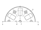
図1に示すように、空気バネ1は、内部の本体側空気室2aに加圧空気が充填され、加圧空気の圧力によって弾力が調整される空気バネ本体2と、この空気バネ本体2の下方に配置され、補助側空気室10aを内部に有する補助タンク10と、空気バネ本体2と補助タンク10との間に介在されたゴムバネ部20とを備え、空気バネ本体2と補助タンク10の双方の内部は連通路30を介して連通されている。
As shown in FIG. 1, the
空気バネ本体2は、上下位置に配置された一対のベース板3,4と、この一対のベース板3,4の間を囲むように固定されたベローズ体5とを備え、これらによって内部に本体側空気室2aが形成されている。上方のベース板3には、センター位置に本体側空気室2aに空気を供給するための空気供給部6が設けられている。下方のベース板4には、そのセンター位置に有底のハンドリング用ネジ孔7が設けられている。このハンドリング用ネジ孔7に上方の空気供給部6から内部に進入させたハンドリング部材(図示せず)をネジ込みで固定し、空気バネの運搬などのハンドリングが容易に行える構造となっている。
The air spring main body 2 includes a pair of
ゴムバネ部20は、上面板21と、下面板22と、これらの間に交互に積層された複数の弾性材23及び剛材24とから構成されている。上面板21は、空気バネ本体2の下方のベース板4にボルト締結部25によって固定されている。下面板22には、そのセンター位置にパイプ部26が下方に向かって突設されている。
The
連通路30は、下方のベース板4に設けられたオリフィス31と、ゴムバネ部20の中心位置を貫通する貫通孔32と、ゴムバネ部20のパイプ部26内のパイプ通路33とから構成されている。
The
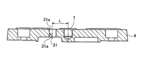
オリフィス31は、図2及び図3にも示すように、ハンドリング用ネジ孔7にオフセットした位置に設けられている。オフセット距離Lは、ベース板4の強度確保の観点より20mm以上が望ましい。又、オリフィス31は、図4に詳しく示すように、従来例とほぼ同一の小径(開口面積)に形成され、且つ、下方のベース板4の板厚t分の孔長さ寸法である。つまり、オリフィス31の加工に際して従来のようにハンドリング用ネジ孔7の制約を受けず、且つ、オリフィス31の形状に加工を施すことができる長さ寸法を有する。
As shown in FIGS. 2 and 3, the
以上の理由により、オリフィス31の内周面は、図4に詳しく示すように、両端に向かうに従って徐々に拡径する拡径面31aに形成されている。この実施形態では、拡径面31aは、円弧面であり、その曲率半径Rは、(1/3)・tに設定されている。
For the above reasons, the inner peripheral surface of the
上記構成において、鉄道車両の振動によって空気バネ本体2内の空気が圧縮(加圧)・膨張(減圧)されると、空気バネ本体2の本体側空気室2aと補助タンク10の補助側空気室10a間の差圧によって双方の空気が連通路30を介して流出入する。そして、空気流が連通路30のオリフィス31を通過する際に発生する摩擦や拡散によって減衰力が得られる。
In the above configuration, when the air in the air spring main body 2 is compressed (pressurized) / expanded (depressurized) by the vibration of the railway vehicle, the main body
ここで、オリフィス31を通過する空気流は、拡径面31aによってオリフィス31の出入口付近をスムーズに流れるため、空気の乱流による高周波音(いわゆる笛吹き音)の発生を抑制できる。つまり従来では、空気流がオリフィスを通過する際に、オリフィスの出入口の角に当たって乱流を引き起こし、この乱硫によって高周波音(いわゆる笛吹き音)が発生していたが、かかる空気の乱流を抑制できることから高周波音の発生を抑制できる。
Here, since the air flow passing through the
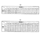
従来例と本実施形態における高周波音の発生状態を実験により比較検討した。この実験状況を具体的に説明する。鉄道車両を支持できる寸法緒元を有する、標準高さにおける有効直径が300〜600φの空気バネにおいて、支持荷重を53.9KN(55ton、内圧250KPa)、空気バネ標準高さを219mmとする。下側加振振幅を1.0〜10.0mmの範囲で、且つ、周波数を0.2〜4.0Hzの範囲内でそれぞれ変化させた時の高周波音の発生状況を調べた。高周波音の発生が認められなかった場合を×、高周波音の発生が認められた場合を○、高周波音の発生がかすかに認められた場合を△で表示すると、従来例では図5(a)の実験結果が、本実施形態では図5(b)の実験結果が得られた。図5(a)、(b)に示すように、従来例では、周波数が1.0Hz以上で高周波音の発生が認められたが、本実施形態では、全ての周波数帯で全く高周波音の発生が認められなかった。 The generation state of high-frequency sound in the conventional example and this embodiment was compared and examined by experiments. This experimental situation will be specifically described. In an air spring having a dimension specification capable of supporting a railway vehicle and having an effective diameter of 300 to 600φ at a standard height, the support load is 53.9 KN (55 ton, internal pressure 250 KPa), and the air spring standard height is 219 mm. The occurrence state of high frequency sound was examined when the lower excitation amplitude was changed in the range of 1.0 to 10.0 mm and the frequency was changed in the range of 0.2 to 4.0 Hz. When the generation of high frequency sound is not recognized, x is indicated when the generation of high frequency sound is recognized, and the case where the generation of high frequency sound is faint is indicated by Δ, in the conventional example, FIG. In this embodiment, the experimental result of FIG. 5B was obtained. As shown in FIGS. 5A and 5B, in the conventional example, the generation of high-frequency sound was recognized at a frequency of 1.0 Hz or more. However, in this embodiment, the generation of high-frequency sound is completely generated in all frequency bands. Was not recognized.
以上、本発明では、ベース板4のハンドリング用ネジ孔7に対してオフセットした位置にオリフィス31が設けられているので、ハンドリング用ネジ孔7の制約を受けることなく、しかも、ベース板4の板厚tの全てをオリフィス31の孔長さ寸法とすることができるため、オリフィス31の設計自由度が高くなり、高周波音を抑制できる形態とすることができる。
As described above, in the present invention, the
具体的には、オリフィス31は、その内周面が両端に向かうに従って拡径する拡径面31aとして形成されているので、オリフィス31を通過する空気流が拡径面31aによってオリフィス31の出入口付近をスムーズに流れるため、空気の乱流による高周波音の発生を抑制できる。
Specifically, since the
又、オリフィス31は、その内周面が拡径面31aに形成されているが、オリフィス31の中央箇所は、最小径dを維持できるため、減衰特性を保持しつつ高周波音の発生を防止できる。
Further, the
図6は、オリフィスの第1変形例の断面図を示す。図6に示すように、第1変形例のオリフィス40は、その内周面の拡径面40aが曲面として形成され、且つ、その曲率半径Rが(1/2)・tに設定されている。
FIG. 6 shows a cross-sectional view of a first variation of the orifice. As shown in FIG. 6, the
この第1変形例でも、前記実施形態と同様に、オリフィス40の最小径dを確保しつつ、内周面を拡径面40aとすることができるため、減衰特性を保持しつつ高周波音の発生を防止できる。
Also in the first modified example, as in the above-described embodiment, since the inner peripheral surface can be the
オリフィス40の曲率半径Rは、(1/3)・t≦R≦(1/2)・tの範囲に設定すれば、オリフィス40の最小径dを確保しつつ、内周面を拡径面とすることができ、好ましい。つまり、曲率半径Rが(1/3)・t未満であれば、空気流のスムーズな流出入を図ることができず、乱流を引き起こす可能性が高い。又、曲率半径Rが(1/2)・tより大きいと、周面の両端にエッジが形成され、乱入を引き起こす可能性が高くなるためである。
If the radius of curvature R of the
図7はオリフィスの第2変形例の断面図である。図7に示すように、第2変形例のオリフィス41は、下方のベース板4の大径孔42に配置され、且つ、支持座部43によって保持された弾性体44に形成されている。そして、オリフィス41の内周面は、ストレートな拡径面41aとして形成されている。
FIG. 7 is a cross-sectional view of a second modification of the orifice. As shown in FIG. 7, the
この第2変形例でも、前記実施形態と同様に、オリフィス41の最小径dを確保しつつ、内周面を拡径面41aとしているため、減衰特性を保持しつつ高周波音の発生を防止できる。又、オリフィス41が弾性体44に形成されているので、弾性体44が空気振動を吸収するため、高周波音の発生を更に抑制できるという利点もある。
Also in the second modified example, as in the above-described embodiment, since the inner peripheral surface is the
1 空気バネ
2 空気バネ本体
2a 本体側空気室
4 ベース板
7 ハンドリング用ネジ孔
10 補助タンク
10a 補助空気室
30 連通孔
31 オリフィス
31a 拡径部
40 オリフィス
40a 拡径部
41 オリフィス
41a 拡径部
44 弾性体
DESCRIPTION OF
Claims (4)
前記オリフィスは、前記ベース板の前記ハンドリング用ネジ孔に対してオフセットした位置に設けられたことを特徴とする空気バネ。 A main body side air chamber is formed inside, an air spring main body in which the main body side air chamber is filled with pressurized air and the elasticity is adjusted by the pressure of the pressurized air, an auxiliary tank having an auxiliary air chamber inside, An air spring comprising a handling screw hole in the base plate of the air spring body, and an orifice communicating the body side air chamber and the auxiliary air chamber,
The air spring according to claim 1, wherein the orifice is provided at a position offset from the handling screw hole of the base plate.
Priority Applications (1)
| Application Number | Priority Date | Filing Date | Title |
|---|---|---|---|
| JP2007033534A JP2008196629A (en) | 2007-02-14 | 2007-02-14 | Air spring |
Applications Claiming Priority (1)
| Application Number | Priority Date | Filing Date | Title |
|---|---|---|---|
| JP2007033534A JP2008196629A (en) | 2007-02-14 | 2007-02-14 | Air spring |
Publications (1)
| Publication Number | Publication Date |
|---|---|
| JP2008196629A true JP2008196629A (en) | 2008-08-28 |
Family
ID=39755761
Family Applications (1)
| Application Number | Title | Priority Date | Filing Date |
|---|---|---|---|
| JP2007033534A Pending JP2008196629A (en) | 2007-02-14 | 2007-02-14 | Air spring |
Country Status (1)
| Country | Link |
|---|---|
| JP (1) | JP2008196629A (en) |
Cited By (5)
| Publication number | Priority date | Publication date | Assignee | Title |
|---|---|---|---|---|
| WO2012105444A1 (en) * | 2011-02-01 | 2012-08-09 | 株式会社ブリヂストン | Air spring device |
| CN103742581A (en) * | 2013-12-04 | 2014-04-23 | 中国飞机强度研究所 | Air spring for suspension support in ground vibration test |
| WO2014127344A3 (en) * | 2013-02-18 | 2015-02-26 | Firestone Industrial Products Company, Llc | End member assemblies as well as gas spring assemblies and methods of manufacture including same |
| CN109210124A (en) * | 2018-11-30 | 2019-01-15 | 中国电子工程设计院有限公司 | A kind of bellows type air spring |
| RU2750341C1 (en) * | 2020-10-15 | 2021-06-28 | Федеральное государственное бюджетное образовательное учреждение высшего образования "Дальневосточный государственный университет путей сообщения" (ДВГУПС) | Pneumatic oscillation damper |
Citations (2)
| Publication number | Priority date | Publication date | Assignee | Title |
|---|---|---|---|---|
| JPH05196083A (en) * | 1992-01-21 | 1993-08-06 | Bridgestone Corp | Air spring |
| JPH11351706A (en) * | 1998-06-11 | 1999-12-24 | Mitsubishi Electric Corp | Refrigerant distributor |
-
2007
- 2007-02-14 JP JP2007033534A patent/JP2008196629A/en active Pending
Patent Citations (2)
| Publication number | Priority date | Publication date | Assignee | Title |
|---|---|---|---|---|
| JPH05196083A (en) * | 1992-01-21 | 1993-08-06 | Bridgestone Corp | Air spring |
| JPH11351706A (en) * | 1998-06-11 | 1999-12-24 | Mitsubishi Electric Corp | Refrigerant distributor |
Cited By (6)
| Publication number | Priority date | Publication date | Assignee | Title |
|---|---|---|---|---|
| WO2012105444A1 (en) * | 2011-02-01 | 2012-08-09 | 株式会社ブリヂストン | Air spring device |
| WO2014127344A3 (en) * | 2013-02-18 | 2015-02-26 | Firestone Industrial Products Company, Llc | End member assemblies as well as gas spring assemblies and methods of manufacture including same |
| US9387865B2 (en) | 2013-02-18 | 2016-07-12 | Firestone Industrial Products Company, Llc | End member assemblies as well as gas spring assemblies and methods of manufacture including same |
| CN103742581A (en) * | 2013-12-04 | 2014-04-23 | 中国飞机强度研究所 | Air spring for suspension support in ground vibration test |
| CN109210124A (en) * | 2018-11-30 | 2019-01-15 | 中国电子工程设计院有限公司 | A kind of bellows type air spring |
| RU2750341C1 (en) * | 2020-10-15 | 2021-06-28 | Федеральное государственное бюджетное образовательное учреждение высшего образования "Дальневосточный государственный университет путей сообщения" (ДВГУПС) | Pneumatic oscillation damper |
Similar Documents
| Publication | Publication Date | Title |
|---|---|---|
| JP4959453B2 (en) | Exhaust pipe support device | |
| US8454002B2 (en) | Fluid filled vibration damping device | |
| JP2008196629A (en) | Air spring | |
| US20160298716A1 (en) | Vibration isolator | |
| JP4922871B2 (en) | Fluid filled vibration isolator | |
| US9566856B2 (en) | Fluid-filled vibration damping device | |
| JP4661694B2 (en) | Intake sound increaser | |
| US7780154B2 (en) | Fluid-filled type engine mount | |
| JPWO2017159826A1 (en) | Vehicle wheel | |
| JP4823117B2 (en) | Liquid-filled vibration isolator | |
| KR20110100163A (en) | Sound insulation structure and sound insulation cover | |
| KR101165210B1 (en) | Air damping mount having a variable orifice hole | |
| JP4855897B2 (en) | Air spring | |
| JP2008115960A (en) | Air spring structure | |
| JP2009052696A (en) | Liquid filled vibration isolator | |
| JP4856024B2 (en) | Air spring | |
| CN104870857B (en) | Inverted type liquid tight mount | |
| JP2009008185A (en) | Liquid sealed type vibration absorption support device | |
| JP2024082428A (en) | Air spring | |
| JP2009036304A (en) | Diaphragm | |
| JP2006128938A (en) | Speaker apparatus | |
| JP2012057476A (en) | Hermetic-type electric compressor | |
| EP4489438A1 (en) | Speaker device | |
| JP6986489B2 (en) | Anti-vibration device | |
| JP4657120B2 (en) | Liquid-filled vibration isolator |
Legal Events
| Date | Code | Title | Description |
|---|---|---|---|
| A621 | Written request for application examination |
Free format text: JAPANESE INTERMEDIATE CODE: A621 Effective date: 20100205 |
|
| A977 | Report on retrieval |
Free format text: JAPANESE INTERMEDIATE CODE: A971007 Effective date: 20110421 |
|
| A131 | Notification of reasons for refusal |
Free format text: JAPANESE INTERMEDIATE CODE: A131 Effective date: 20110426 |
|
| A02 | Decision of refusal |
Free format text: JAPANESE INTERMEDIATE CODE: A02 Effective date: 20110906 |