JP2008201416A - 鋳造サスペンションメンバの製造方法 - Google Patents
鋳造サスペンションメンバの製造方法 Download PDFInfo
- Publication number
- JP2008201416A JP2008201416A JP2008140629A JP2008140629A JP2008201416A JP 2008201416 A JP2008201416 A JP 2008201416A JP 2008140629 A JP2008140629 A JP 2008140629A JP 2008140629 A JP2008140629 A JP 2008140629A JP 2008201416 A JP2008201416 A JP 2008201416A
- Authority
- JP
- Japan
- Prior art keywords
- suspension member
- mounting base
- mounting
- manufacturing
- suspension
- Prior art date
- Legal status (The legal status is an assumption and is not a legal conclusion. Google has not performed a legal analysis and makes no representation as to the accuracy of the status listed.)
- Granted
Links
Images


Landscapes
- Body Structure For Vehicles (AREA)
Abstract
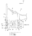
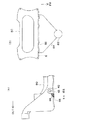
【解決手段】サスペンションアームの端部を支持する後側取付ベース26の板厚を前側取付ベース24よりも厚く設定することで、前者の剛性が後者の剛性よりも相対的に高くなっている。組付時には剛性が低い(板厚が薄い)方の前側取付ベース24が変形するため、組付応力は小さくなる。また、荷重入力に対する強度確保は、剛性が高い(板厚が厚い)方の後側取付ベース26が受け持つ。上記構成のサスペンションメンバを製造するにあたっては、下型64と上型66の鋳抜き方向を本来の抜き勾配分だけ片側(反時計方向)に振ることにより、後側取付ベース26の外側の面26Bを最初から垂直面にすることができる。
【選択図】図6
Description
20 ステアリングギヤボックス
22 フロントサスペンションアーム
24 前側取付ベース(一方の取付壁)
26 後側取付ベース(他方の取付壁)
30 前側アーム取付部
32 後側アーム取付部
34 ブッシュ
36 ボルト(締結具)
38 ナット(締結具)
42 ギヤボックス取付部(取付座)
50 補強リブ
64 下型(成形型)
66 上型(成形型)
84 湯道
90 切残し部
92 フロントサスペンションメンバ
F 入力
Claims (1)
- サスペンションアームの端部を挟み込むように揺動可能に締結具で取り付けるための一対の取付壁を備えた鋳造サスペンションメンバの製造方法であって、
成形型の鋳抜き方向を本来の抜き勾配分だけ片側へ振ることにより、一方の取付壁の外側の面を前記サスペンションアームの端部の取付面に対して平行にした、
ことを特徴とする鋳造サスペンションメンバの製造方法。
Priority Applications (1)
| Application Number | Priority Date | Filing Date | Title |
|---|---|---|---|
| JP2008140629A JP4780145B2 (ja) | 2008-05-29 | 2008-05-29 | 鋳造サスペンションメンバの製造方法 |
Applications Claiming Priority (1)
| Application Number | Priority Date | Filing Date | Title |
|---|---|---|---|
| JP2008140629A JP4780145B2 (ja) | 2008-05-29 | 2008-05-29 | 鋳造サスペンションメンバの製造方法 |
Related Parent Applications (1)
| Application Number | Title | Priority Date | Filing Date |
|---|---|---|---|
| JP2003181586A Division JP2005014737A (ja) | 2003-06-25 | 2003-06-25 | 鋳造サスペンションメンバ構造及び鋳造サスペンションメンバの製造方法 |
Publications (2)
| Publication Number | Publication Date |
|---|---|
| JP2008201416A true JP2008201416A (ja) | 2008-09-04 |
| JP4780145B2 JP4780145B2 (ja) | 2011-09-28 |
Family
ID=39779323
Family Applications (1)
| Application Number | Title | Priority Date | Filing Date |
|---|---|---|---|
| JP2008140629A Expired - Fee Related JP4780145B2 (ja) | 2008-05-29 | 2008-05-29 | 鋳造サスペンションメンバの製造方法 |
Country Status (1)
| Country | Link |
|---|---|
| JP (1) | JP4780145B2 (ja) |
Cited By (3)
| Publication number | Priority date | Publication date | Assignee | Title |
|---|---|---|---|---|
| JP2012118095A (ja) * | 2010-11-29 | 2012-06-21 | Stanley Electric Co Ltd | 2面コーナーリフレクタアレイ光学素子およびその製造方法並びに2面コーナーリフレクタアレイ光学素子を用いた表示装置 |
| JP2014000850A (ja) * | 2012-06-15 | 2014-01-09 | Honda Motor Co Ltd | 車両用サブフレーム |
| JP2019536689A (ja) * | 2016-12-06 | 2019-12-19 | ルノー エス.ア.エス.Renault S.A.S. | 車両のアルミニウムサイドレールと制御アームの結合装置 |
Citations (4)
| Publication number | Priority date | Publication date | Assignee | Title |
|---|---|---|---|---|
| JPH04306111A (ja) * | 1991-03-31 | 1992-10-28 | Mazda Motor Corp | サスペンションアームの取付構造 |
| JPH06340274A (ja) * | 1993-06-01 | 1994-12-13 | Hitachi Metals Ltd | 車両のサスペンションクロスメンバー |
| JPH08198134A (ja) * | 1995-01-22 | 1996-08-06 | Mitsubishi Motors Corp | アルミニウム合金製クロスメンバ |
| JP2003127892A (ja) * | 2001-10-23 | 2003-05-08 | Toyota Motor Corp | サスペンションメンバ |
-
2008
- 2008-05-29 JP JP2008140629A patent/JP4780145B2/ja not_active Expired - Fee Related
Patent Citations (4)
| Publication number | Priority date | Publication date | Assignee | Title |
|---|---|---|---|---|
| JPH04306111A (ja) * | 1991-03-31 | 1992-10-28 | Mazda Motor Corp | サスペンションアームの取付構造 |
| JPH06340274A (ja) * | 1993-06-01 | 1994-12-13 | Hitachi Metals Ltd | 車両のサスペンションクロスメンバー |
| JPH08198134A (ja) * | 1995-01-22 | 1996-08-06 | Mitsubishi Motors Corp | アルミニウム合金製クロスメンバ |
| JP2003127892A (ja) * | 2001-10-23 | 2003-05-08 | Toyota Motor Corp | サスペンションメンバ |
Cited By (3)
| Publication number | Priority date | Publication date | Assignee | Title |
|---|---|---|---|---|
| JP2012118095A (ja) * | 2010-11-29 | 2012-06-21 | Stanley Electric Co Ltd | 2面コーナーリフレクタアレイ光学素子およびその製造方法並びに2面コーナーリフレクタアレイ光学素子を用いた表示装置 |
| JP2014000850A (ja) * | 2012-06-15 | 2014-01-09 | Honda Motor Co Ltd | 車両用サブフレーム |
| JP2019536689A (ja) * | 2016-12-06 | 2019-12-19 | ルノー エス.ア.エス.Renault S.A.S. | 車両のアルミニウムサイドレールと制御アームの結合装置 |
Also Published As
| Publication number | Publication date |
|---|---|
| JP4780145B2 (ja) | 2011-09-28 |
Similar Documents
| Publication | Publication Date | Title |
|---|---|---|
| US9688309B2 (en) | Suspension tower plate and suspension tower | |
| JP6915592B2 (ja) | 下部車体構造 | |
| JP2019123344A (ja) | 下部車体構造 | |
| US10005412B2 (en) | Vehicle front portion structure | |
| WO2014125723A1 (ja) | 自動車のダンパーハウジング構造 | |
| CN115140164A (zh) | 副车架 | |
| JP4780145B2 (ja) | 鋳造サスペンションメンバの製造方法 | |
| JP2022152260A (ja) | サブフレーム | |
| JP2024092174A (ja) | 車両後部構造 | |
| JP2022152262A (ja) | サブフレーム | |
| JP2005014737A (ja) | 鋳造サスペンションメンバ構造及び鋳造サスペンションメンバの製造方法 | |
| JP2005014728A (ja) | 鋳造サスペンションメンバ構造 | |
| CN116738740B (zh) | 大压铸件的结构优化方法及装置 | |
| JP3523782B2 (ja) | 自動車のサブフレーム構造 | |
| EP2508414B1 (en) | Body of an industrial vehicle with seat base integrated to the floor and method for realizing a body of an industrial vehicle | |
| JP2008149888A (ja) | パワープラントの支持構造 | |
| KR101619877B1 (ko) | 엠보싱 보강패널이 적용된 이종소재 서브프레임 | |
| JP2010149725A (ja) | クロスメンバ締結構造 | |
| CN223355520U (zh) | 前围下骨架连接板总成及车辆 | |
| JP2009126207A (ja) | パワーユニット支持構造 | |
| CN220842705U (zh) | 前机舱稳定横梁、车辆的前机舱结构及车辆 | |
| JP3223733B2 (ja) | 自動車用バンパ | |
| JP3849575B2 (ja) | サブフレーム取付構造 | |
| MX2012001251A (es) | Partes hibridas de magnesio y procesos. | |
| JP3968691B2 (ja) | エンジンマウントブラケット |
Legal Events
| Date | Code | Title | Description |
|---|---|---|---|
| A621 | Written request for application examination |
Free format text: JAPANESE INTERMEDIATE CODE: A621 Effective date: 20080529 |
|
| A977 | Report on retrieval |
Free format text: JAPANESE INTERMEDIATE CODE: A971007 Effective date: 20101029 |
|
| A131 | Notification of reasons for refusal |
Free format text: JAPANESE INTERMEDIATE CODE: A131 Effective date: 20101116 |
|
| A521 | Written amendment |
Free format text: JAPANESE INTERMEDIATE CODE: A523 Effective date: 20110114 |
|
| TRDD | Decision of grant or rejection written | ||
| A01 | Written decision to grant a patent or to grant a registration (utility model) |
Free format text: JAPANESE INTERMEDIATE CODE: A01 Effective date: 20110607 |
|
| A01 | Written decision to grant a patent or to grant a registration (utility model) |
Free format text: JAPANESE INTERMEDIATE CODE: A01 |
|
| A61 | First payment of annual fees (during grant procedure) |
Free format text: JAPANESE INTERMEDIATE CODE: A61 Effective date: 20110620 |
|
| FPAY | Renewal fee payment (event date is renewal date of database) |
Free format text: PAYMENT UNTIL: 20140715 Year of fee payment: 3 |
|
| R151 | Written notification of patent or utility model registration |
Ref document number: 4780145 Country of ref document: JP Free format text: JAPANESE INTERMEDIATE CODE: R151 |
|
| FPAY | Renewal fee payment (event date is renewal date of database) |
Free format text: PAYMENT UNTIL: 20140715 Year of fee payment: 3 |
|
| LAPS | Cancellation because of no payment of annual fees |