JP2008242545A - Automatic transaction equipment - Google Patents
Automatic transaction equipment Download PDFInfo
- Publication number
- JP2008242545A JP2008242545A JP2007078134A JP2007078134A JP2008242545A JP 2008242545 A JP2008242545 A JP 2008242545A JP 2007078134 A JP2007078134 A JP 2007078134A JP 2007078134 A JP2007078134 A JP 2007078134A JP 2008242545 A JP2008242545 A JP 2008242545A
- Authority
- JP
- Japan
- Prior art keywords
- operation process
- input
- unit
- displayed
- display
- Prior art date
- Legal status (The legal status is an assumption and is not a legal conclusion. Google has not performed a legal analysis and makes no representation as to the accuracy of the status listed.)
- Pending
Links
Images


Abstract
【課題】 入力手順にしたがって配列された各取引工程領域と入力ボタン領域とがともに拡張と縮小を順次行うことにより、視認性と操作性が良好な取引工程を備えた自動取引装置を提供する。
【解決手段】 表示装置15に、操作手順に従って上下に配列される複数の操作工程表示部511を備えた操作工程表示領域510と、前記操作工程表示部511に対応して配列される複数の操作工程入力部541とを備えた操作工程入力領域540とを左右に配置した1つの操作画面500を表示し、複数の前記操作工程表示部511と前記操作工程入力部541は、常に1つの前記操作工程表示部511Aと対応する前記操作工程入力部541Aが入力状態となって、他の前記操作工程表示部511Bと前記操作工程入力部541Bより、上下方向に拡張して表示し、拡張された前記操作工程表示部511Aには操作ガイダンス512を表示し、拡張された前記操作工程入力部541Aには入力キー542を表示する。
【選択図】 図1PROBLEM TO BE SOLVED: To provide an automatic transaction apparatus having a transaction process with good visibility and operability by sequentially expanding and contracting each transaction process area and input button area arranged according to an input procedure.
SOLUTION: An operation process display area 510 having a plurality of operation process display units 511 arranged vertically according to an operation procedure on the display device 15, and a plurality of operations arranged corresponding to the operation process display units 511. One operation screen 500 in which an operation process input area 540 provided with a process input unit 541 is arranged on the left and right is displayed, and a plurality of the operation process display units 511 and the operation process input units 541 always have one operation. The operation process input unit 541A corresponding to the process display unit 511A is in an input state, and is expanded and displayed in the vertical direction from the other operation process display unit 511B and the operation process input unit 541B. An operation guidance 512 is displayed on the operation process display unit 511A, and an input key 542 is displayed on the expanded operation process input unit 541A.
[Selection] Figure 1
Description
本発明は、タッチパネル表示装置に操作ボタンを備えた各種の取引画面を表示して自動取引を行う自動取引装置に関するものであり、特に、工程数の多い自動取引を行う自動取引装置に関するものである。 The present invention relates to an automatic transaction apparatus that displays various transaction screens having operation buttons on a touch panel display device and performs automatic transactions, and particularly relates to an automatic transaction apparatus that performs automatic transactions with a large number of processes. .
従来より、銀行や証券会社などでは、タッチパネル表示装置に各種の取引画面を表示して、各種の取引を利用者が行う自動取引装置が普及している。その代表的な自動取引装置が現金自動預入支払機(以下ATMという)である。このATMによれば、利用者自身が取引画面を操作することにより、現金の引き出しや預け入れ、更には、振込みなどの取引を行うことができる。 2. Description of the Related Art Conventionally, in banks and securities companies, automatic transaction apparatuses that display various transaction screens on a touch panel display device and allow users to perform various transactions have become widespread. A typical automatic transaction apparatus is an automatic teller machine (hereinafter referred to as ATM). According to this ATM, the user himself / herself operates a transaction screen, so that it is possible to conduct transactions such as withdrawal and deposit of cash, and further transfer.
しかしながら、利用者が操作する取引工程が少ない現金の引き出しや預け入れは広く利用されているが、取引工程の長い振込み取引などは操作が分かりづらいとの課題が指摘されている。そこで、これらの課題を解決するために多くの改善策が提案されている。 However, cash withdrawals and deposits with few transaction processes operated by users are widely used, but it has been pointed out that transfer transactions with long transaction processes are difficult to understand. Therefore, many improvement measures have been proposed to solve these problems.
例えば、1つの表示画面に取引工程領域と入力表示領域を分割して表示し、前記取引工程領域に選択可能な取引工程ボタンを順次表示し、入力表示領域には前記取引工程ボタンの選択に対応して同取引工程における入力ボタン群を表示し、この入力ボタン群の入力内容を前記取引工程ボタン内に表示しながら取引工程を進めるものがある。 For example, a transaction process area and an input display area are divided and displayed on one display screen, selectable transaction process buttons are sequentially displayed in the transaction process area, and the input process area corresponds to the selection of the transaction process button. Then, there are those that display an input button group in the transaction process and advance the transaction process while displaying the input contents of the input button group in the transaction process button.
前記従来例によれば、利用者は取引の全工程を取引工程領域で把握することができるとともに、個々の入力を取引工程領域の選択に伴って入力表示領域に順次表示される入力ボタン群を介して進めることができる。しかしながら、これら従来例では、取引工程領域に配列される複数の取引工程ボタンを小さく表示しなければ成らず、この取引工程ボタンの選択にともなって入力表示領域の全面積を利用して表示される入力ボタン群とのバランスが悪く、取引工程ボタンと入力ボタン群の関連性が分かり難いという課題がある。これらの従来例では、選択された取引工程ボタンを強調表示することで、取引工程ボタンと入力ボタン群の関連性を出しているものの、ボタンの大きさのバランスが悪いため、ボタンの関連性の分かり難さが改善されていない。 According to the conventional example, the user can grasp the entire process of the transaction in the transaction process area, and the input button group which is sequentially displayed in the input display area in accordance with the selection of the transaction process area. Can proceed through. However, in these conventional examples, a plurality of transaction process buttons arranged in the transaction process area must be displayed in a small size, and the entire area of the input display area is displayed in accordance with the selection of the transaction process button. There is a problem that the balance between the input button group is poor and the relationship between the transaction process button and the input button group is difficult to understand. In these conventional examples, the relationship between the transaction process button and the input button group is given by highlighting the selected transaction process button, but the button size is poorly balanced. The intelligibility has not improved.
そこで、この発明の目的とするところは、入力手順にしたがって配列された各取引工程領域と入力ボタン領域とがともに拡張と縮小を順次行うことにより、視認性と操作性が良好な取引工程を備えた自動取引装置を提供することにある。 Accordingly, an object of the present invention is to provide a transaction process with good visibility and operability by sequentially expanding and contracting each transaction process area and the input button area arranged according to the input procedure. It is to provide an automatic transaction apparatus.
本発明に係る自動取引装置は、前記目的を達成するために、表示装置に、操作手順に従って上下に配列される複数の操作工程表示部を備えた操作工程表示領域と、前記操作工程表示部に対応して配列される複数の操作工程入力部とを備えた操作工程入力領域とを左右に配置した1つの操作画面を表示し、複数の前記操作工程表示部と前記操作工程入力部は、常に1つの前記操作工程表示部と対応する前記操作工程入力部が入力状態となって、他の前記操作工程表示部と前記操作工程入力部より、上下方向に拡張して表示し、拡張された前記操作工程表示部には操作ガイダンスを表示し、拡張された前記操作工程入力部には入力キーを表示する。 In order to achieve the above object, the automatic transaction apparatus according to the present invention provides a display device with an operation process display area having a plurality of operation process display units arranged vertically according to an operation procedure, and the operation process display unit. A single operation screen in which left and right operation process input areas having a plurality of operation process input units arranged correspondingly are displayed, and a plurality of the operation process display units and the operation process input units are always The operation process input unit corresponding to one of the operation process display units is in an input state, and is expanded and displayed in the vertical direction from the other operation process display unit and the operation process input unit. An operation guidance is displayed on the operation process display unit, and an input key is displayed on the expanded operation process input unit.
本発明によれば、複数の操作工程表示部と、この操作工程表示部に対応する複数の操作工程入力部が表形式で表示され、入力状態では拡張して操作ガイダンスや入力キーが表示され、他の状態では縮小表示されるので、長い取引工程であっても視認性と操作性が良好となる。 According to the present invention, a plurality of operation process display units and a plurality of operation process input units corresponding to the operation process display units are displayed in a table format, and expanded in the input state, operation guidance and input keys are displayed, Since it is displayed in a reduced size in other states, visibility and operability are good even in a long transaction process.
以下、図1から図9を参照して、本発明に係る実施の形態を説明する。この実施の形態は、銀行システムなどの金融機関システムに採用される例えばATM(Automatic Teller Machine)のような自動取引装置に関する。図1はATMの概略構造図、図2は銀行システムのネットワーク構成図、図3が振り込み工程の動作フロー図、図4から図9が取引画面図である。 Embodiments according to the present invention will be described below with reference to FIGS. This embodiment relates to an automatic transaction apparatus such as an ATM (Automatic Teller Machine) employed in a financial institution system such as a bank system. FIG. 1 is a schematic structural diagram of an ATM, FIG. 2 is a network configuration diagram of a bank system, FIG. 3 is an operation flow diagram of a transfer process, and FIGS. 4 to 9 are transaction screen diagrams.
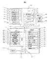
先ず、図1に示すATM1の概略説明図を参照して、本実施の形態に係るATMの概略構造を説明する。
First, the schematic structure of the ATM according to the present embodiment will be described with reference to the schematic explanatory diagram of the
図1において、符号1で総括的に示すのは、金融機関等のロビーなどに設置される自動取引装置である。本実施の形態では、自動取引装置1としてATMの例で説明する。自動取引装置1は、直方体の前面上方の一部分が側面から見てL字形に切り欠かれた開口部を有する本体筐体10と、L字形の開口部を塞ぐように配置され、側面から見てL字形に形成されたフロントパネル11とから構成されている。
In FIG. 1, what is generally indicated by
本体筐体10は、前面が開口したベース筐体12と、このベース筐体12の前面下方に設けられた板状の前面扉13と、ベース筐体12の背面に配置された板状の背面扉14とを有している。ベース筐体12は、各種の取引処理を行う機構部、例えば、図2に示す、タッチパネル付表示部220、カード部221、通帳明細印字部222、伝送制御部223、記憶装置部224、硬貨入出金部225、紙幣入出金部226、電源部227、センサ部228、制御部229等を内蔵している。タッチパネル付表示部220は情報の入力装置および出力装置としての機能を備えており、カード部221はIDカード212(図2参照)の読取装置および出力装置としての機能を備えている。そして、タッチパネル付表示部220の操作表示部15や各部の媒体口18、19、23、24や生体認証部の生体情報読取部22は、フロントパネル11から露出するように配置されている。
The
L字形のフロントパネル11は、本体正面の垂直面を形成するパネル部16と、水平面を構成するテーブル部17とを備えている。本実施形態では、垂直面を構成する前記パネル部16の中央に媒体口であるカード/明細票取扱口18や通帳取扱口19からなる媒体取扱部20が配置され、水平面を構成するテーブル部17の中央に操作表示部15、その両側にハンドセット21と生体認証部の生体情報読取部22が配置され、水平面と垂直面の角部には媒体口である紙幣挿入/排出口23と硬貨挿入/排出口24が並設されている。
The L-
本実施の形態の大きな特徴の1つは、操作工程の多い振込み工程において、操作表示部15に、操作手順に従って上下に配列される複数の操作工程表示部511を備えた操作工程表示領域510と、前記操作工程表示部511に対応して配列される複数の操作工程入力部541とを備えた操作工程入力領域540とを左右に配置した1つの操作画面500を表示する。そして、複数の前記操作工程表示部511と前記操作工程入力部541は、常に1つの前記操作工程表示部511Aと対応する前記操作工程入力部541Aが入力状態となっており、他の入力状態にない前記操作工程表示部511Bと前記操作工程入力部541Bより、上下方向に拡張して表示することにある。
One of the major features of the present embodiment is that an operation
即ち、この実施の形態に係る振込み工程の操作画面500は、左側に、振り込み先の「金融機関」や「支店名」、「口座番号」などの複数の操作工程表示部511が操作手順にしたがって上下に配列される操作工程表示領域510が表示される。また、操作画面500の右側には、前記複数の操作工程表示部511のそれぞれに対応して配列される複数の操作工程入力部541が配列される操作工程入力領域540が表示される。このため、複数の操作工程表示部511と操作工程入力部541とが操作手順にしたがって表形式で表示されるので、操作工程表示部511の配列により操作手順の全体を把握しやすいとともに、この操作工程表示部511に対応して操作工程入力部541を配列しているので、操作工程表示部511と操作工程入力部541との関連性が明確と成る。
That is, on the left side of the transfer
そして、これらの複数の操作工程表示部511と操作工程入力部541は、常に1つの前記操作工程表示部511Aと対応する前記操作工程入力部541Aが入力状態となって上下方向に拡張表示されるとともに、他の入力状態にない操作工程表示部511Bと操作工程入力部541Bは小さく表示されるので、現在作業中の操作工程表示部や操作工程入力部を把握することができ、入力作業における視認性や操作性が良好と成る。
The plurality of operation
また、本実施の形態の他の大きな特徴の1つは、入力状態の拡張された前記操作工程入力部541Aには入力キー542を表示し、入力状態の拡張された前記操作工程表示部511Aには操作ガイダンス512を表示する。これにより、操作工程表示部511と操作工程入力部541の関連性を崩すことなく、拡張した領域に入力作業に必要な入力キー542と操作ガイダンス512を表示することができる。
Another major feature of the present embodiment is that an
また、本実施の形態の他の大きな特徴の1つは、前記操作工程表示部511は、入力状態にない状態では操作工程の名称513が表示され、前記操作工程入力部541は、入力が完了すると、当該入力内容543が表示される。これにより、各操作工程における入力の有無とその入力内容を一目で把握することができる。
Another major feature of the present embodiment is that the operation
なお、図1の吹き出し内には、振込み工程の初期画面である操作画面500Aと、最初の操作工程である「金融機関」の入力が完了して次の操作工程である「支店名」の操作工程の操作画面500Bを図示している。「金融機関」の操作工程の入力が完了すると、操作画面500Aで拡張表示されていた入力状態にある「金融機関」の操作工程表示部511Aと入力状態にある操作工程入力部541Aが、矢印P1の方向に縮小して表示され、逆に、次の工程である「支店名」の操作工程表示部511Aと操作工程入力部541Aが、矢印P2の方向に拡張して表示され、入力可能な操作画面500Bに切り替えられる。これらの動作は、制御部229によって制御される。
In the balloon of FIG. 1, the
以下、図2から図9を参照して、この実施の形態に係る金融機関システムを更に詳細に説明する。 Hereinafter, the financial institution system according to this embodiment will be described in more detail with reference to FIGS.
先ず、図2を参照して、このATM1が設置される銀行システムとATM1の装置構成を説明する。図2は銀行システムのネットワーク構成図である。この銀行システムでは、この銀行システムを統括するセンタ100に対して複数の営業店舗200や専門センタ350がネットワーク300で接続されている。前記営業店舗200には、店舗ネットワーク211を介して複数の機器が接続され、これら機器が前記ネットワーク300を介して前記センタ100や前記専門センタ350と接続され、この銀行システムを利用する顧客に対して各種の金融サービスを提供することができる。この他、この銀行システムには前記ネットワーク300を介して他の金融システムや各種のサービスサイトに接続することができる。
First, with reference to FIG. 2, the bank system in which this ATM1 is installed and the device configuration of the ATM1 will be described. FIG. 2 is a network configuration diagram of the bank system. In this bank system, a plurality of
前記センタ100は、HUBサーバ150を介して他の営業店舗200や専門センタ350と接続することで、銀行内の全ての情報を統括管理している。このHUBサーバ150は、ゲートウエイサーバを兼用するものであり、チャネル系APサーバ群を統括する統合チャネルサーバ110と、勘定系ホスト140と、各種の新商品情報データを備えた新商品サーバ130と、全ての顧客情報を統括的に管理する顧客情報管理サーバ116などが接続される。
The
統合チャネルサーバ110は、前記ネットワーク300を介して営業店舗200と接続されて、営業店舗200に各種の情報を提供する支援システムである。この統合チャネルサーバ110の統括下には、IBコンテンツデータを備えたIBサーバ111と、営業店のコンテンツデータを備えた営業店APサーバ112と、来店顧客情報データを備えた来店管理サーバ113と、商品のコンテンツデータを備えた商品情報サーバ114と、行員情報データを備えた行員管理サーバ115と、顧客情報データを備えた顧客管理サーバ120とを備えている。
The
一方、営業店舗200は、店舗ネットワーク211を介して各種装置が接続されている。例えば、このシステムでは、ATM(現金自動預払機)1、顧客の店舗の出入りを管理する受付端末208、顧客の各種の相談に対応する相談端末207、顧客に各種の情報を提供する情報テーブル端末206、行員が顧客に対して相談や商談を薦める相談テーブル端末205、行員が顧客に対して各種サービスを行う窓口PC端末204、前記窓口PC端末204を支援する後方PC端末203、各種の金融関連装置からなる金融デバイス202、店舗内の各種情報を管理する営業店サーバ201、店舗内の無線通信や位置検知を行う店舗通信システム210などが設けられている。
On the other hand, various devices are connected to the
また、この銀行システムでは、顧客が所有する携帯端末213や、この銀行が顧客に提供するIDカード212などを介して各種の情報を提供することができる。
Further, in this bank system, various information can be provided via a
前記ATM1は、このATM1を統括する制御部229の統括の下、タッチパネル付表示部220、IDカード212やキャッシュカードなどの各種のカードに対して読み取りや書き込みを行うカード部221と、通帳の書き込みを行う通帳明細印字部222と、店舗ネットワーク211に接続するための伝送制御部223と、各種のデータを記憶する記憶装置部224と、硬貨入出金部225と、紙幣入出金部226と、電源部227と、センサ部228とを含んで構成される。
Under the control of the
また、この実施の形態では、このATM1のタッチパネル付表示部220に表示される前記振込み画面500などの取引画面を、このATM1内で生成して表示させることができる。この場合、制御部229がタッチパネル付表示部220の操作指示に基づいて、統合チャネルサーバ110から必要な取引データを収集するとともに、前記記憶装置224から所定の取引画面データを呼び出して取引フローに沿った取引画面を生成し、この生成した取引画面を前記タッチパネル付表示部220に表示しながら取引を進めるものである。
Moreover, in this embodiment, transaction screens, such as the said
一方、他の実施の形態として、統合チャネルサーバ110で生成した取引画面を呼び出してタッチパネル付表示部220に表示しながら取引を進めるようにしてもよい。この場合、制御部229は、ネットワーク300を介して統合チャネルサーバ110に接続するための端末機としての制御を主体に動作させる。このように、ATM1を統合チャネルサーバ110にアクセスするための端末機として動作させることにより、各種のデータを端末装置であるATM1に持つ必要が無いので、情報の集中化が実現できる。
On the other hand, as another embodiment, a transaction screen generated by the
以下の説明では、ATM1で振込み画面500を生成する実施例で説明するが、統合チャネルサーバ110で生成するようにしても良い。
In the following description, an example in which the
次に、図3から図9を参照してこの実施の形態の特徴的な振込み工程の操作画面500の動作フローを主体に説明する。
Next, with reference to FIG. 3 to FIG. 9, the operation flow of the
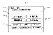
先ず、この実施の形態では、前記センサ部228を介して利用者がATM1に接近したことを検知すると、制御部229は、図4に示すメニュー画面400を前記記憶装置部224から読み出して操作表示部15に表示する。このメニュー画面400は、上下に2分割され、上部にガイダンス表示領域401、下部に複数の取引ボタン403,404が表示される選択ボタン表示領域402とを含んで構成される。選択ボタン表示領域402には、利用頻度の高い取引ボタン403が利用頻度の低い取引ボタン404より大きく表示されている。そして、ガイダンス表示領域401には「いらっしゃいませ。お取引のボタンに軽く手を触れてください」との操作を促すガイダンスが表示される。
First, in this embodiment, when it is detected that the user has approached
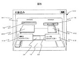
前記制御部229は、前記複数の取引ボタン403あるいは複数の取引ボタン404から1つの取引ボタンが選択されると、当該取引ボタンに対応する取引画面に移行する前に図5に示す認証画面410を表示する。ここでは、メニュー画面400において、「お振込み」の取引ボタン403aが選択されたとして、以下説明を行う。
When one transaction button is selected from the plurality of
図5において、認証画面410には、操作表示部15や各部の媒体口18、19、23、24を表したATM1の外観図411が表示され、媒体口18、19にカードと通帳を挿入するアニメーション412と操作ガイダンス413が表示されている。利用者が媒体口18にカード、または媒体口19に通帳を挿入すると、制御部229は、挿入されたカードまたは通帳から認証情報を読み取るとともに、暗証番号の入力を促す図6の暗証番号画面420を表示する。
In FIG. 5, the
この暗証番号画面420は、上部に「暗証番号(4ケタ)を入力してください」との操作ガイダンスが表示されるガイダンス表示領域421が設けられ、その下部にはテンキー422と確認表示部423と確認キー424とを含んで構成される入力領域425を備えている。利用者がテンキー422で数値を入力すると、その内容が確認表示部423に表示される。そして確認キー424を選択することで、制御部229は、この入力された暗証番号とカードまたは通帳から読み込んだ認証情報との照合を行って、一致すれば、図7に示す振込み工程の操作画面500を表示する。
This
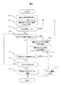
以下、この振込み工程の操作画面500の動作フローを図3の動作フロー図に基づいて、図7から図9を参照して説明する。
Hereinafter, the operation flow of the
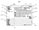
先ず、図3及び図7において、制御部229は、暗証番号と認証情報との照合が一致すすれば、図7に示す振込み工程の最初の操作画面500Aを表示する(ステップ600)。この図7に示す最初の操作画面500Aは、入力状態にある「金融機関」の操作工程表示部511Aと操作工程入力部541Aとが最上部に配置され、下部に配列される入力状態にない他の複数の操作工程表示部511Bと操作工程入力部541Bより上下方向の長さが広い領域として表示される。
First, in FIG. 3 and FIG. 7, the
前記「金融機関」の操作工程表示部511Aには、操作ガイダンス512として、この操作工程が「金融機関」の入力工程であり、「振込先の金融機関を押し「確認」を押してください。」が表示される。一方、「金融機関」の操作工程入力部541Aには、複数の文字入力キーからなる前記入力キー542と、この入力キー542の入力内容を表示する確認表示部544と、確認ボタン545などが設けられている。
In the operation
また、入力状態でない前記操作工程表示部511Bは、「支店名」や「口座番号」など、それぞれの操作工程の名称513が表示される。なお、この操作工程の名称513には、四角形状のチェックボックスが設けられ、前記確認表示部544で入力が完了すると、このチェックボックスがマークされる。これにより、利用者は入力の完了の有無を知ることができる。一方、入力状態でない操作工程入力部541Bは、まだ入力が完了していないので、チェックボックスが空欄となっている。
Further, the operation
また、この実施の形態では、操作工程表示部511の夫々が、選択ボタンの機能を有している。したがって、制御部229は、操作工程表示部511の何れか1つが選択されると、当該選択された操作工程表示部511と対応する操作工程入力部541とを拡張表示する。以下、この動作フローで説明を行うが、この動作フローに限定されるものではない。例えば、制御部229が、操作工程表示部511の順番(操作手順)に従って、上方から下方に向かった入力が完了すると次の操作工程表示部511が選択されたとして自動選択を行う動作フローでもよい。
In this embodiment, each of the operation
さて、制御部229は、図7の操作画面500Aを表示すると、入力状態の操作工程入力部541Aからの入力を受け付ける(ステップ602)。例えば、制御部229は、入力キー542から金融機関名が入力されると、この入力内容を確認表示部544に表示する。そして、確認ボタン545が選択されると、制御部229は、入力が完了したと判定する(ステップ604)。次に、制御部229は、他の入力状態でない前記操作工程表示部511Bの選択を監視する(ステップ606)。
When the
そして、例えば、利用者が「支店名」の前記操作工程表示部511Bを選択すると、制御部229は、現在選択されている「金融機関」の入力状態の操作工程表示部511Aと操作工程入力部541Aを縮小表示しつつ(ステップ608)、新たに選択された「支店名」の入力状態の前記操作工程表示部511Aと操作工程入力部541Aを、図8で示すように拡張表示する(ステップ610)。そして、ステップ602に戻り、当該入力状態の操作工程入力部541Aからの入力を受け付ける。
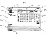
For example, when the user selects the operation
図8、図9は、他の操作工程表示部511が選択された操作画面500B、500Cを示している。図8に示す操作画面500Bは、「金融機関の支店名」の入力工程の操作画面の事例を示している。この操作画面500Bでは、「金融機関の支店名」の操作工程表示部511Aと対応する操作工程入力部541Aが入力状態となって拡張表示される。一方、図7の操作画面500Aでは拡張表示されていた「金融機関」の操作工程表示部511Aと、この操作工程表示部511Aと対応する操作工程入力部541Aが縮小表示され、入力状態が解除された状態(入力状態にない操作工程表示部511Bおよび操作工程入力部541Bの状態)となる。しかし、その操作工程入力部541Bには、先の入力内容が表示され、操作工程表示部511のチェックボックスにチェックマークが表示されるので、利用者は「金融機関」が入力されていることを知ることができる。
8 and 9 show operation screens 500B and 500C in which another operation
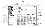
また、図9は、最終の入力工程である「振込み金額」の入力工程の操作画面500Cを示している。この操作画面でも、入力状態にある「振込み金額」の操作工程表示部511Aと、この操作工程表示部511Aと対応する入力状態にある操作工程入力部541Aが拡張表示される。一方、入力状態にない上段の操作工程表示部511Bと対応する操作工程入力部541Bは縮小表示される。しかし、それらの操作工程入力部541Bには、先の入力内容が表示され、操作工程表示部511のチェックボックスにチェックマークが表示される。
FIG. 9 shows an operation screen 500C of the input process of “transfer amount” which is the final input process. Also on this operation screen, the operation
なお、この実施の形態では、入力状態の操作工程入力部541Aには、入力内容に対応して多様な入力キー542が表示される。例えば、図7、図8では文字入力キーを主体とした入力キー542であるが、図9の入力キー542は数値キーが主体のものとして表示する。ここで、この「振込み金額」の入力工程の操作画面500Cでは、手数料欄546が設けられており、この手数料欄546には、振込み金額や振込先、振込み時間帯等の条件に基づいて制御部229が算出した手数料が表示されるようになっている。
In this embodiment,
図3に戻り、制御部229は、ステップ606において、他の操作工程入力部541が選択されず前記タイトルバー501の取消ボタン502が選択されたか否かを監視している。そして、取消ボタン502が選択されると、制御部229はメニュー画面400に戻らせる。
Returning to FIG. 3, in
また、制御部229は、全ての入力工程において入力が完了しているか否かを監視しており(ステップ614)、入力が完了していなければ、ステップ606に戻し、入力が完了していれば、統合チャンネルサーバ110に入力内容を送信する(ステップ616)。
In addition, the
そして、制御部229は、統合チャンネルサーバ110からの手続き完了の通知を受け付けると、操作表示部15に図示しないカードまたは通帳の返却画面を表示し、この返却動作を確認すると、元のメニュー画面400を表示して手続きを終了する。
When the
以上述べたように、この実施の形態によれば、複数の操作工程表示部と、この操作工程表示部に対応する複数の操作工程入力部が表形式で表示され、入力状態では拡張して操作ガイダンスや入力キーが表示され、他の状態では縮小表示されるので、長い取引工程であっても視認性と操作性が良好となる。 As described above, according to this embodiment, a plurality of operation process display units and a plurality of operation process input units corresponding to the operation process display units are displayed in a table format, and are expanded and operated in the input state. Since guidance and input keys are displayed and displayed in a reduced state in other states, visibility and operability are improved even in a long transaction process.
なお、前記したように、他の応用例として、図3において、ステップ606の判定を制御部229が操作手順にしたがって、自動的に選択するようにしてもよい。
As described above, as another application example, the
また、ステップ614において、操作画面500に図示しない送信ボタンを設け、この送信ボタンの選択を受け付けて、この選択操作に基づいて、ステップ614に移行するようにすると、利用者が全ての入力後に内容確認を行うことができる。
In
また、この実施の形態では、確認表示部544を操作工程入力部541に設けるようにしたが、操作工程表示部511に設けることにより、入力キー542の配置スペースを拡張して大きな操作ボタンを配置することができ、スペース効率を向上させることができる。
In this embodiment, the
1…ATM、10…本体筐体、11…フロントパネル、12…ベース筐体、13…前面扉、14…背面扉、15…操作表示部、16…パネル部、17…テーブル部、18…カード/明細票取扱口、19…通帳取扱口、20…媒体取扱部、21…ハンドセット、22…生体情報読取部、23…紙幣挿入/排出口、24…硬貨挿入/排出口、100…センタ、110…統合チャネルサーバ、111…IBサーバ、112…営業店APサーバ、113…来店管理サーバ、114…商品情報サーバ、115…行員管理サーバ、116…顧客情報管理サーバ、120…顧客管理サーバ、130…新商品サーバ、140…勘定系ホスト、150…HUBサーバ、200…営業店舗、201…営業店サーバ、202…金融デバイス、203…後方PC端末、204…窓口PC端末、205…相談テーブル端末、206…情報テーブル端末、207…相談端末、208…受付端末、210…店舗通信システム、211…店舗ネットワーク、212…IDカード、213…携帯端末、220…タッチパネル付表示部、221…カード部、222…通帳明細印字部、223…伝送制御部、224…記憶装置部、225…硬貨入出金部、226…紙幣入出金部、227…電源部、228…センサ部、229…制御部、300…ネットワーク、350…専門センタ、400…メニュー画面、401…ガイダンス表示領域、402…表示領域、403…取引ボタン、404…取引ボタン、410…認証画面、420…暗証番号画面、421…ガイダンス表示領域、422…テンキー、423…確認表示部、424…確認キー、425…入力領域、501…タイトルバー、502…取消ボタン、510…操作工程表示領域、511…操作工程表示部、511A…入力状態の操作工程表示部、511B…入力状態でない前記操作工程表示部、512…操作ガイダンス、513…操作工程の名称、540…操作工程入力領域、541…操作工程入力部、541A…入力状態の操作工程入力部、541B…入力状態でない操作工程入力部、542…入力キー、500、500A,500B、500C…操作画面、543…入力内容、544…確認表示部、545…確認ボタン。
DESCRIPTION OF
Claims (2)
前記表示装置に、操作手順に従って上下に配列される複数の操作工程表示部を備えた操作工程表示領域と、前記操作工程表示部に対応して配列される複数の操作工程入力部とを備えた操作工程入力領域とを左右に配置した1つの操作画面を表示し、
複数の前記操作工程表示部と前記操作工程入力部は、常に1つの前記操作工程表示部と対応する前記操作工程入力部が入力状態となって、他の前記操作工程表示部と前記操作工程入力部より、上下方向に拡張して表示され、
拡張された前記操作工程表示部には操作ガイダンスが表示され、
拡張された前記操作工程入力部には入力キーが表示される
ことを特徴とする自動取引装置。 In an automatic transaction apparatus that is connected to a host computer via a communication line and displays an operation screen of various transactions on the display screen of the display device to perform the transaction,
The display device includes an operation process display area including a plurality of operation process display units arranged vertically according to an operation procedure, and a plurality of operation process input units arranged corresponding to the operation process display units. Display one operation screen with left and right operation process input area,
The plurality of operation process display units and the operation process input units are always in an input state of the operation process input unit corresponding to one operation process display unit, and the other operation process display units and the operation process input units. It is displayed by expanding vertically from the
Operation guidance is displayed on the expanded operation process display section,
An automatic transaction apparatus, wherein an input key is displayed on the expanded operation process input section.
前記操作工程表示部は、他の状態では操作工程の名称が表示され、
前記操作工程入力部は、拡張された入力状態では前記入力キーの入力内容を表示する確認表示部が表示され、入力が完了した他の状態では当該入力内容が表示される
ことを特徴とする自動取引装置。 The automatic transaction apparatus according to claim 1,
The operation process display unit displays the name of the operation process in other states,
The operation process input unit displays a confirmation display unit that displays the input content of the input key in an expanded input state, and displays the input content in another state in which the input is completed. Trading device.
Priority Applications (1)
| Application Number | Priority Date | Filing Date | Title |
|---|---|---|---|
| JP2007078134A JP2008242545A (en) | 2007-03-26 | 2007-03-26 | Automatic transaction equipment |
Applications Claiming Priority (1)
| Application Number | Priority Date | Filing Date | Title |
|---|---|---|---|
| JP2007078134A JP2008242545A (en) | 2007-03-26 | 2007-03-26 | Automatic transaction equipment |
Publications (1)
| Publication Number | Publication Date |
|---|---|
| JP2008242545A true JP2008242545A (en) | 2008-10-09 |
Family
ID=39913860
Family Applications (1)
| Application Number | Title | Priority Date | Filing Date |
|---|---|---|---|
| JP2007078134A Pending JP2008242545A (en) | 2007-03-26 | 2007-03-26 | Automatic transaction equipment |
Country Status (1)
| Country | Link |
|---|---|
| JP (1) | JP2008242545A (en) |
Cited By (1)
| Publication number | Priority date | Publication date | Assignee | Title |
|---|---|---|---|---|
| JP2023183782A (en) * | 2022-06-16 | 2023-12-28 | 株式会社大塚製薬工場 | Information input support system, information input support method, and program |
-
2007
- 2007-03-26 JP JP2007078134A patent/JP2008242545A/en active Pending
Cited By (2)
| Publication number | Priority date | Publication date | Assignee | Title |
|---|---|---|---|---|
| JP2023183782A (en) * | 2022-06-16 | 2023-12-28 | 株式会社大塚製薬工場 | Information input support system, information input support method, and program |
| JP7844267B2 (en) | 2022-06-16 | 2026-04-13 | 株式会社大塚製薬工場 | Information input support system, information input support method, and program |
Similar Documents
| Publication | Publication Date | Title |
|---|---|---|
| JP2003067816A (en) | Automatic depositing and dispensing machine | |
| JP5099986B2 (en) | Automatic transaction equipment | |
| JP4972296B2 (en) | Automatic transaction apparatus, transaction approval method using the same, and transaction approval program for automatic transaction apparatus | |
| JP2008242546A (en) | Information processing device | |
| JP5505397B2 (en) | Automatic transaction equipment | |
| JP2008242545A (en) | Automatic transaction equipment | |
| JP5104167B2 (en) | Window business processing system | |
| KR100315947B1 (en) | Handy terminal for banking account | |
| JP5372334B2 (en) | Automatic transaction equipment | |
| JP4654002B2 (en) | Information display device | |
| JP4997871B2 (en) | Automatic transaction equipment | |
| JP4706346B2 (en) | Automatic transaction equipment | |
| JP5055935B2 (en) | Automatic transaction system and automatic transaction device | |
| JPH05242132A (en) | Automatic transaction device and automatic transaction method | |
| JP2006134011A (en) | Automatic transaction equipment | |
| JP5691570B2 (en) | Monitoring monitor system, automatic transaction apparatus and monitoring monitor | |
| JP5458736B2 (en) | Automated trading system | |
| JP2012003559A (en) | Automatic transaction device and automatic transaction system | |
| JP2006267307A (en) | Automatic transaction equipment | |
| JPH10261133A (en) | Automatic transaction device and control method thereof | |
| JP2006133922A (en) | Automatic transaction device display method | |
| JPH1040447A (en) | Trading system and trading device | |
| JPH11272768A (en) | Automatic transaction device and automatic transaction method | |
| KR20090047308A (en) | Withdrawal menu of automatic teller machine | |
| JP2006053639A (en) | Charge payment system |