JP2008273473A - Electric power steering device - Google Patents
Electric power steering device Download PDFInfo
- Publication number
- JP2008273473A JP2008273473A JP2007122296A JP2007122296A JP2008273473A JP 2008273473 A JP2008273473 A JP 2008273473A JP 2007122296 A JP2007122296 A JP 2007122296A JP 2007122296 A JP2007122296 A JP 2007122296A JP 2008273473 A JP2008273473 A JP 2008273473A
- Authority
- JP
- Japan
- Prior art keywords
- steering
- amount
- command value
- failure
- sensor
- Prior art date
- Legal status (The legal status is an assumption and is not a legal conclusion. Google has not performed a legal analysis and makes no representation as to the accuracy of the status listed.)
- Pending
Links
Images


Landscapes
- Steering Control In Accordance With Driving Conditions (AREA)
- Power Steering Mechanism (AREA)
- Control Of Electric Motors In General (AREA)
Abstract
【課題】トルクセンサの失陥後にハンドルを切り戻したときの違和感を軽減することが可能な電動パワーステアリング装置を提供する。
【解決手段】本発明の電動パワーステアリング装置11の構成によれば、操舵シャフト32の捻れ量の変化量θxが、トルクセンサ35の失陥時の前後で予め定められた基準値K1を超えて大きくなったか否かに基づいて、ハンドル33の切り戻しの有無を判別することができる。そして、ハンドル33の切り戻し有りと判別したときに、アシスト指令値Ixとしてアシストモータ19に付与されていた減衰過渡指令値Ibを強制的に0にすることで、電動パワーステアリング装置11からのアシスト力の付与が停止され、そのアシスト力が切り戻し動作の妨げになる事態を防ぐことができる。これにより、トルクセンサ35の失陥後に切り戻しを行った際の違和感を従来より軽減することが可能になる。
【選択図】図2An electric power steering apparatus capable of reducing a sense of incongruity when a steering wheel is turned back after a failure of a torque sensor is provided.
According to the configuration of the electric power steering apparatus 11 of the present invention, the amount of change θx of the twist amount of the steering shaft 32 exceeds a predetermined reference value K1 before and after the failure of the torque sensor 35. Whether or not the handle 33 is switched back can be determined on the basis of whether or not it has become larger. Then, when it is determined that the steering wheel 33 is switched back, the assist from the electric power steering apparatus 11 is forcibly set to 0 to the damping transient command value Ib given to the assist motor 19 as the assist command value Ix. It is possible to prevent the situation where the application of force is stopped and the assist force hinders the switching back operation. As a result, it is possible to reduce the uncomfortable feeling when switching back after the failure of the torque sensor 35 than before.
[Selection] Figure 2
Description
本発明は、操舵負荷トルクに応じて決定されるアシスト指令値に基づいてモータを駆動し、ハンドルの操舵を補助する電動パワーステアリング装置に関する。 The present invention relates to an electric power steering apparatus that drives a motor based on an assist command value determined according to a steering load torque and assists steering of a steering wheel.
一般に、この種の電動パワーステアリング装置は、トルクセンサが失陥した場合には、アシスト力無しのマニュアル操舵に切り替わる。しかしながら、トルクセンサの失陥と同時にマニュアル操舵に切り替わると、アシスト力の消失によって操舵負荷トルクが急増し、運転者に不安感を抱かせることになる。これに対し、従来の電動パワーステアリング装置として、操舵負荷トルクに応じて第1のアシスト指令値を決定する通常時用の制御系と、操舵負荷トルクとは無関係に操舵角に応じて第2のアシスト指令値を決定する非常時用の制御系とを備えておき、トルクセンサの失陥と同時に第1のアシスト指令値を用いた制御から第2のアシスト指令値を用いた制御に切り替え、その第2のアシスト指令値を徐々に減衰させてマニュアル操舵に移行する構成のものが知られている(例えば、特許文献1参照)。
ところで、上記した電動パワーステアリング装置では、第2のアシスト指令値は操舵角に基づいて決定されているので、例えば、ハンドルを中立点より左側に切った状態で右側に切り戻した場合、ハンドルが中立点を超えて右側に切られるまでは、第2のアシスト指令値によるアシストトルクは、ハンドルの切り戻し動作を妨げる方向に作用し、運転者に違和感を与える事態が生じ得た。 By the way, in the electric power steering apparatus described above, the second assist command value is determined based on the steering angle. For example, when the steering wheel is turned back to the right side after being turned to the left side from the neutral point, the steering wheel is Until the vehicle is turned to the right after exceeding the neutral point, the assist torque according to the second assist command value acts in a direction that hinders the steering wheel turning back operation, which may cause the driver to feel uncomfortable.
本発明は、上記事情に鑑みてなされたもので、トルクセンサの失陥後にハンドルを切り戻したときの違和感を軽減することが可能な電動パワーステアリング装置の提供を目的とする。 The present invention has been made in view of the above circumstances, and an object of the present invention is to provide an electric power steering apparatus capable of reducing a sense of incongruity when the steering wheel is turned back after a failure of a torque sensor.
上記目的を達成するためになされた請求項1の発明に係る電動パワーステアリング装置(11)は、車両(10)の運転状況に応じて決定されるアシスト指令値(Ix)に基づいてモータ(19)を駆動して、ハンドル(33)の操舵を補助するためのアシスト力を出力する電動パワーステアリング装置(11)であって、ハンドル(33)の操舵に対する操舵負荷トルク(T1)を検出するためのトルクセンサ(35)と、トルクセンサ(35)が検出した操舵負荷トルク(T1)に基づいてアシスト指令値(Ix)としての通常指令値(Ia)を決定する通常指令値決定手段(S3,100)と、トルクセンサ(35)が失陥した場合に、予め定められた減衰時間(t2)に亘って、失陥時直前の通常指令値(Ia)から徐々に0へと減衰する減衰過渡指令値(Ib)をアシスト指令値(Ix)として生成する減衰過渡指令値生成手段(SS8,102)と、ハンドル(33)の切り戻しの有無を判別する切り戻し判別手段(S6,103)と、減衰過渡指令値(Ib)が0に至る前に、ハンドル(33)の切り戻し有りと判別されたときに、減衰過渡指令値(Ib)を強制的に0にする強制終了手段(S10,101)とを備え、切り戻し判別手段(S6,103)は、車両(10)の旋回時に捻れ変形する可撓部材(10,32)の捻れ量の変化量(θx)が、トルクセンサ(35)の失陥時の前後で予め定められた基準値(K1)を超えて大きくなったときに、ハンドル(33)の切り戻し有りと判別するように構成されたところに特徴を有する。 The electric power steering device (11) according to the first aspect of the present invention, which has been made to achieve the above object, includes a motor (19) based on an assist command value (Ix) determined according to the driving situation of the vehicle (10). ) To output an assist force for assisting the steering of the handle (33) to detect the steering load torque (T1) for the steering of the handle (33). Torque command (35) and normal command value determining means (S3) for determining a normal command value (Ia) as an assist command value (Ix) based on the steering load torque (T1) detected by the torque sensor (35). 100) and when the torque sensor (35) fails, it gradually decreases from the normal command value (Ia) immediately before the failure to 0 over a predetermined decay time (t2). Attenuating transient command value generating means (SS8, 102) for generating a damping transient command value (Ib) to be used as an assist command value (Ix), and a switching back determining means (S6, S6) for determining whether the handle (33) is switched back or not. 103) and forcibly ending means for forcibly setting the damping transient command value (Ib) to 0 when it is determined that the steering wheel (33) is switched back before the damping transient command value (Ib) reaches 0. (S10, 101), and the switchback determination means (S6, 103) is configured such that the amount of change (θx) in the torsional amount of the flexible member (10, 32) that is torsionally deformed when the vehicle (10) turns is torque It is characterized in that when the sensor (35) becomes larger than a predetermined reference value (K1) before and after the failure of the sensor (35), it is determined that the handle (33) is switched back. .
なお、本発明において、「通常指令値(Ia)が0になる」ことは、「通常指令値(Ia)がアシスト力をなくすための数値になる」ことを意味する。従って、「通常指令値(Ia)」の具体的な数値が、例えば、オフセット値等を含むために具体的な数値の「0」になっていなくても、その「通常指令値(Ia)」が「アシスト力をなくす」ための数値であれば、本発明上では「通常指令値(Ia)は0である」ということができる。「減衰過渡指令値(Ib)」に関しても同様である。 In the present invention, “the normal command value (Ia) becomes 0” means “the normal command value (Ia) becomes a numerical value for eliminating the assist force”. Accordingly, even if the specific numerical value of the “normal command value (Ia)” is not the specific numerical value “0” because it includes an offset value, for example, the “normal command value (Ia)” Can be said to be “normal command value (Ia) is 0” in the present invention. The same applies to the “damping transient command value (Ib)”.
請求項2の発明は、請求項1に記載の電動パワーステアリング装置(11)において、ハンドル(33)と共に回転する操舵シャフト(32)に取り付けられてハンドル(33)の操舵角(θ1)を検出する舵角センサ(34)と、モータ(19)の出力回転角(θ2)を検出するためのモータ回転位置センサ(25)とを備え、切り戻し判別手段(S6,103)は、舵角センサ(34)及びモータ回転位置センサ(25)の検出結果に基づいて可撓部材(32)としての操舵シャフト(32)の捻れ量の変化量(θx)を検出するところに特徴を有する。 According to a second aspect of the present invention, in the electric power steering device (11) according to the first aspect, the steering angle (θ1) of the handle (33) is detected by being attached to the steering shaft (32) rotating together with the handle (33). And a motor rotation position sensor (25) for detecting the output rotation angle (θ2) of the motor (19), and the switchback discrimination means (S6, 103) includes a steering angle sensor (34) and the amount of change (θx) in the twist amount of the steering shaft (32) as the flexible member (32) is detected based on the detection results of the motor rotational position sensor (25).
請求項3の発明は、請求項1又は2に記載の電動パワーステアリング装置(11)において、ハンドル(33)と共に回転する操舵シャフト(32)に取り付けられてハンドル(33)の操舵角(θ1)を検出する舵角センサ(34)と、車両(10)にかかる横G(G1)を検出するための横Gセンサとを備え、切り戻し判別手段(S6,103)は、トルクセンサ(35)の失陥時の前後で、操舵角(θ1)の変化量(θy)が予め定められた第1基準値(K2)を超えて大きくなり、かつ、横G(G1)の変化量(Gy)が予め定められた第2基準値(K3)より小さいことを条件にして、可撓部材(10)としての車両(10)全体の捻れ量の変化量が、トルクセンサ(35)の失陥時の前後で基準値を超えて大きくなったと推定するところに特徴を有する。 According to a third aspect of the present invention, in the electric power steering apparatus (11) according to the first or second aspect, the steering angle (θ1) of the steering wheel (33) is attached to the steering shaft (32) rotating together with the steering wheel (33). The steering angle sensor (34) for detecting the lateral G and the lateral G sensor for detecting the lateral G (G1) applied to the vehicle (10), and the switchback discriminating means (S6, 103) is a torque sensor (35). The amount of change (θy) in the steering angle (θ1) becomes larger than a predetermined first reference value (K2) and the amount of change (Gy) in the lateral G (G1). Is smaller than the predetermined second reference value (K3), the amount of change in the amount of twist of the entire vehicle (10) as the flexible member (10) is when the torque sensor (35) fails. Estimated to be larger than the reference value before and after Having the features the time.
請求項4の発明は、請求項1乃至3の何れかに記載の電動パワーステアリング装置(11)において、ハンドル(33)と共に回転する操舵シャフト(32)に取り付けられてハンドル(33)の操舵角(θ1)を検出する舵角センサ(34)と、車両(10)に備えた左右の車輪(50)の回転速度(NL,NR)を検出可能な回転速度センサ(36L,36R)とを備え、切り戻し判別手段(S6,103)は、トルクセンサ(35)の失陥時の前後で、操舵角(θ1)の変化量(θy)が予め定められた第1基準値(K2)を超えて大きくなり、かつ、左右の車輪(50)の回転速度差(W1)の変化量(Wy)が、予め定められた第3基準値(K4)より小さいことを条件にして、可撓部材(10)としての車両(10)全体の捻れ量の変化量が、トルクセンサ(35)の失陥時の前後で基準値を超えて大きくなったと推定するところに特徴を有する。 According to a fourth aspect of the present invention, in the electric power steering apparatus (11) according to any one of the first to third aspects, the steering angle of the handle (33) is attached to the steering shaft (32) rotating together with the handle (33). A steering angle sensor (34) for detecting (θ1) and a rotation speed sensor (36L, 36R) capable of detecting the rotation speed (NL, NR) of the left and right wheels (50) provided in the vehicle (10). The switch-back determination means (S6, 103) indicates that the change amount (θy) of the steering angle (θ1) exceeds a predetermined first reference value (K2) before and after the failure of the torque sensor (35). On the condition that the change amount (Wy) of the rotational speed difference (W1) between the left and right wheels (50) is smaller than a predetermined third reference value (K4). 10) The total amount of twist of the vehicle (10) as Amount change has a characteristic where the estimate that has become larger than the reference value before and after the time of failure of the torque sensor (35).
請求項5の発明は、請求項1乃至4の何れかに記載の電動パワーステアリング装置(11)において、ハンドル(33)と共に回転する操舵シャフト(32)に取り付けられてハンドル(33)の操舵角(θ1)を検出する舵角センサ(34)と、車両(10)のヨーレート(R1)を検出するヨーレート検出部とを備え、切り戻し判別手段(S6,103)は、トルクセンサ(35)の失陥時の前後で、操舵角(θ1)の変化量(θy)が予め定められた第1基準値(K2)を超えて大きくなり、かつ、ヨーレートの変化量(Ry)が、予め定められた第3基準値より小さいことを条件にして、可撓部材(10)としての車両(10)全体の捻れ量の変化量が、トルクセンサ(35)の失陥時の前後で基準値を超えて大きくなったと推定するところに特徴を有する。 According to a fifth aspect of the present invention, in the electric power steering apparatus (11) according to any one of the first to fourth aspects, the steering angle of the steering wheel (33) is attached to the steering shaft (32) rotating together with the steering wheel (33). The steering angle sensor (34) for detecting (θ1) and the yaw rate detector for detecting the yaw rate (R1) of the vehicle (10) are provided, and the switchback discriminating means (S6, 103) is provided by the torque sensor (35). Before and after the failure, the change amount (θy) of the steering angle (θ1) exceeds the predetermined first reference value (K2), and the change amount (Ry) of the yaw rate is determined in advance. On the condition that it is smaller than the third reference value, the amount of change in the twist amount of the entire vehicle (10) as the flexible member (10) exceeds the reference value before and after the failure of the torque sensor (35). It is estimated that Having the features the time.
[請求項1の発明]
ハンドルを切って車両が旋回している状態では、ハンドルと車輪(転舵輪)との間を連結する操舵系部品が捻れ変形すると共に、車両全体も捻れ変形する。また、ハンドルを切り戻すと、それら操舵系部品及び車両全体の捻れ量が減少する。請求項1の電動パワーステアリング装置では、上記した操舵系部品、車両全体のように、車両の旋回時に捻れ変形する可撓部材の捻れ量の変化量が、トルクセンサの失陥時の前後で予め定められた基準値を超えて大きくなったか否かによって、ハンドルの切り戻しの有無を判別することができる。そして、ハンドルの切り戻し有りと判別したときに、減衰過渡指令値を強制的に0にすることで、アシスト力が切り戻し動作の妨げになる事態を防ぎ、トルクセンサの失陥後に切り戻しを行った際の違和感を従来より軽減することができる。
[Invention of Claim 1]
In a state where the steering wheel is turned and the vehicle is turning, the steering system parts connecting the steering wheel and the wheels (steered wheels) are twisted and deformed, and the entire vehicle is also twisted and deformed. Further, when the steering wheel is turned back, the amount of twisting of the steering system parts and the entire vehicle is reduced. In the electric power steering apparatus according to the first aspect, the amount of change in the amount of twist of the flexible member that twists and deforms when the vehicle turns, such as the above-described steering system parts and the vehicle as a whole, is changed before and after the failure of the torque sensor. Whether or not the steering wheel is turned back can be determined based on whether or not the value exceeds a predetermined reference value. Then, when it is determined that the steering wheel has been turned back, the damping transient command value is forcibly set to 0 to prevent the assist force from interfering with the turning back operation. The uncomfortable feeling at the time of going can be reduced conventionally.
[請求項2の発明]
請求項2の構成によれば、舵角センサ及びモータ回転位置センサの検出結果に基づいて可撓部材としての操舵シャフトの捻れ量の変化量を検出し、その操舵シャフトの捻れ量の変化量が、トルクセンサの失陥時の前後で予め定められた基準値を超えて大きくなったか否かに応じて、ハンドルの切り戻し有無を判別することができる。
[Invention of claim 2]
According to the configuration of the second aspect, the change amount of the twist amount of the steering shaft as the flexible member is detected based on the detection results of the steering angle sensor and the motor rotation position sensor, and the change amount of the twist amount of the steering shaft is detected. Whether or not the steering wheel is turned back can be determined depending on whether or not the torque sensor exceeds a predetermined reference value before and after the failure of the torque sensor.
[請求項3の発明]
請求項3の構成によれば、トルクセンサの失陥時の前後で、操舵角の変化量が予め定められた第1基準値を超えて大きくなり、かつ、横Gの変化量が予め定められた第2基準値より小さいことを条件にして、可撓部材としての車両全体の捻れ量の変化量が、トルクセンサの失陥時の前後で基準値を超えて大きくなったと推定して、ハンドルの切り戻し有無を判別することができる。
[Invention of claim 3]
According to the configuration of the third aspect, before and after the failure of the torque sensor, the change amount of the steering angle becomes larger than the predetermined first reference value, and the change amount of the lateral G is determined in advance. Assuming that the amount of change in the torsion amount of the entire vehicle as the flexible member exceeds the reference value before and after the failure of the torque sensor on the condition that it is smaller than the second reference value, the steering wheel It is possible to determine whether or not to switch back.
[請求項4の発明]
請求項4の構成によれば、トルクセンサの失陥時の前後で、操舵角の変化量が予め定められた第1基準値を超えて大きくなり、かつ、左右の車輪の回転速度差の変化量が、予め定められた第3基準値より小さいことを条件にして、可撓部材としての車両全体の捻れ量の変化量が、トルクセンサの失陥時の前後で基準値を超えて大きくなったと推定して、ハンドルの切り戻し有無を判別することができる。
[Invention of claim 4]
According to the configuration of the fourth aspect, before and after the failure of the torque sensor, the amount of change in the steering angle becomes larger than a predetermined first reference value, and the change in the rotational speed difference between the left and right wheels is increased. On the condition that the amount is smaller than a predetermined third reference value, the amount of change in the torsion amount of the entire vehicle as the flexible member becomes larger than the reference value before and after the failure of the torque sensor. It can be estimated that the steering wheel has been switched back.
[請求項5の発明]
請求項5の構成によれば、トルクセンサの失陥時の前後で、操舵角の変化量が予め定められた第1基準値を超えて大きくなり、かつ、ヨーレートの変化量が、予め定められた第4基準値より小さいことを条件にして、可撓部材としての車両全体の捻れ量の変化量が、トルクセンサの失陥時の前後で基準値を超えて大きくなったと推定して、ハンドルの切り戻し有無を判別することができる。
[Invention of claim 5]
According to the configuration of claim 5, before and after the failure of the torque sensor, the change amount of the steering angle becomes larger than a predetermined first reference value, and the change amount of the yaw rate is determined in advance. Assuming that the amount of change in the torsion amount of the entire vehicle as the flexible member exceeds the reference value before and after the failure of the torque sensor on the condition that it is smaller than the fourth reference value, the steering wheel It is possible to determine whether or not to switch back.
[第1実施形態]
以下、本発明の一実施形態を図1〜図8に基づいて説明する。図1に示した車両10には、本発明に係る電動パワーステアリング装置11が搭載されている。この電動パワーステアリング装置11は、両転舵輪50,50(車輪)の間に差し渡された転舵輪間シャフト16にアシストモータ19を連結して備えている。転舵輪間シャフト16は筒形ハウジング18の内部に挿通され、その両端はタイロッド17,17を介して各転舵輪50,50に連結されている。また、筒形ハウジング18は、車両本体10Hに固定されている。
[First Embodiment]
Hereinafter, an embodiment of the present invention will be described with reference to FIGS. An electric
アシストモータ19は、筒形ハウジング18の内面に嵌合固定されたステータ20と、ステータ20の内側に遊嵌された筒状のロータ21とを備えてなり、そのロータ21の内側を転舵輪間シャフト16が貫通している。そして、ロータ21の内面に固定されたボールナット22と、転舵輪間シャフト16の外面に形成されたボールネジ部23とが螺合し、ロータ21が回転するとボールネジ部23が直動して転舵輪50,50が転舵する。
The
転舵輪間シャフト16の一端部側には、ラック30が形成され、操舵シャフト32の下端部に備えたピニオン31がこのラック30に噛合している。操舵シャフト32の上端部には、ハンドル33が取り付けられると共に、操舵シャフト32の中間部には、トルクセンサ35が取り付けられ、そのトルクセンサ35とハンドル33との間に舵角センサ34が取り付けられている。そして、舵角センサ34にてハンドル33の操舵角θ1を検出し、トルクセンサ35により操舵負荷トルクT1を検出している。また、左右の転舵輪50,50の近傍には、それら転舵輪50,50の回転速度を別々に検出可能な回転速度センサ36L,36Rが設けられている。
A
なお、上記したアシストモータ19には、アシストモータ19の位置制御を行うためにアシストモータ19の出力回転角θ2を検出可能なモータ回転位置センサ25が備えられている。
The
さて、電動パワーステアリング装置11に備えた操舵制御装置41は、所定周期で、例えば図2に示した操舵制御プログラムPG1を実行してアシスト指令値Ixを決定し、図1に示したモータ駆動回路42にそのアシスト指令値Ixを付与する。すると、モータ駆動回路42が、そのアシスト指令値Ixに応じたモータ駆動電流をアシストモータ19に流して駆動し、この結果、ハンドル33の操舵を補助するアシスト力が電動パワーステアリング装置11から出力される。
The
詳細には、図2に示すように操舵制御プログラムPG1が実行されると、操舵制御装置41が、回転速度センサ36L,36R、トルクセンサ35、舵角センサ34、モータ回転位置センサ25の各検出結果(右前輪回転速度NR、左前輪回転速度NL、操舵負荷トルクT1、操舵角θ1、モータ回転角θ2)を取得する(S1)。そして、トルクセンサ35が失陥しているか否かを判別する(S2)。
Specifically, as shown in FIG. 2, when the steering control program PG1 is executed, the
なお、トルクセンサ35の検出結果が予め設定された上限値を超えた場合や、操舵角θ1が変化しているにも関わらずトルクセンサ35の検出結果が0である場合に、トルクセンサ35が失陥しているものと判断される。また、操舵制御プログラムPG1の実行により図7に示した制御系が構成され、さらに上記ステップS2の実行により、同図の制御系におけるトルクセンサ失陥判別部109とスイッチ108が構成される。
When the detection result of the
トルクセンサ35が失陥していなかった場合には、本発明の「通常指令値決定手段」に相当する通常指令値決定処理(S3)を実行する。この処理(S3)では、図3に示すように、まず、操舵負荷トルクT1から基礎電流指令値I11を決定する(S31)。具体的には、予め設定されたトルク−電流指令値マップmp1(図6参照)を用いて操舵負荷トルクT1に対応した基礎電流指令値I11を決定する。なお、このトルク−電流指令値マップmp1は、操舵負荷トルクT1が大きくなるに従って、基礎電流指令値I11が大きくなるように設定されている。
If the
次いで、操舵角θ1を時間微分して操舵角速度ωを求め、その操舵角速度ωに応じた付加電流指令値I12を決定する(S32)。具体的には、予め設定された操舵角速度−電流指令値マップmp2(図6参照)を用いて操舵角速度ωに対応した付加電流指令値I12を決定する。なお、この操舵角速度−電流指令値マップmp2は、操舵角速度ωが大きくなるに従って、付加電流指令値I12が大きくなるように設定されている。 Next, the steering angle θ1 is time-differentiated to obtain the steering angular velocity ω, and the additional current command value I12 corresponding to the steering angular velocity ω is determined (S32). Specifically, the additional current command value I12 corresponding to the steering angular velocity ω is determined using a preset steering angular velocity-current command value map mp2 (see FIG. 6). The steering angular velocity-current command value map mp2 is set so that the additional current command value I12 increases as the steering angular velocity ω increases.
次いで、車速Vとして右前輪回転速度NRと左前輪回転速度NLとの平均値を求める(S33)。そして、車速Vに応じたゲインG1を決定する(S34)。具体的には、予め設定された、車速−ゲインマップmp3(図6参照)を用いて車速Vに対応したゲインG1を決定する。なお、この車速−ゲインマップmp3は、車速Vが大きくなるに従ってゲインG1が小さくなるように設定されている。 Next, an average value of the right front wheel rotational speed NR and the left front wheel rotational speed NL is obtained as the vehicle speed V (S33). Then, the gain G1 corresponding to the vehicle speed V is determined (S34). Specifically, a gain G1 corresponding to the vehicle speed V is determined using a preset vehicle speed-gain map mp3 (see FIG. 6). The vehicle speed-gain map mp3 is set so that the gain G1 decreases as the vehicle speed V increases.
そして、上記した基礎電流指令値I11、付加電流指令値I12及びゲインG1を用いて、下記式(1)から通常電流指令値Ia(本発明の「通常指令値」に相当する)を演算する(S35)。 Then, using the basic current command value I11, the additional current command value I12, and the gain G1, the normal current command value Ia (corresponding to the “normal command value” of the present invention) is calculated from the following equation (1) ( S35).
Ia=G1・(I11−I12) ・・・・・・(1) Ia = G1 (I11-I12) (1)
なお、上記した通常指令値決定処理(S3)の実行により、図6及び図7のブロック図で示した制御系の通常指令値決定部100が構成される。
The normal command
図2に示すように、操舵制御プログラムPG1では、通常指令値決定処理(S3)から抜けると、データバッファ処理(S4)を行う。ここで、操舵制御装置41に備えたメモリ(図示せず)の記憶領域に操舵角レジスタθsと、モータ回転位置レジスタθmとが設定されており、データバッファ処理(S4)が行われる度に、舵角センサ34の最新の検出値である操舵角θ1が操舵角レジスタθsに格納(記憶)されかつ、モータ回転位置センサ25の最新の検出値であるモータ回転角θ2がモータ回転位置レジスタθmに格納(記憶)される。
As shown in FIG. 2, in the steering control program PG1, when the normal command value determination process (S3) is exited, a data buffer process (S4) is performed. Here, the steering angle register θs and the motor rotation position register θm are set in a storage area of a memory (not shown) provided in the
次いで、上記通常指令値決定処理(S3)によって決定した通常電流指令値Iaの値をアシスト指令値Ixに設定し(S5)、そのアシスト指令値Ixとしての通常電流指令値Iaをモータ駆動回路42に付与して(S11)、操舵制御プログラムPG1から抜ける。
Next, the value of the normal current command value Ia determined by the normal command value determination process (S3) is set to the assist command value Ix (S5), and the normal current command value Ia as the assist command value Ix is set to the
上記したステップS2において、トルクセンサ35が失陥していた場合には、本発明の「切り戻し判別手段」に相当する切り戻し判別処理(S6)を実行する。また、トルクセンサ35が失陥した場合には、図示しないタイマが起動し、トルクセンサ35の失陥時からの経過時間である失陥経過時間t1が計測される。
If the
切り戻し判別処理(S6)では、下記式(2)を用いてトルクセンサ35の失陥時前後の操舵シャフト32の捻れ量の変化量θxを演算する(図4のS20)。
In the switchback determination process (S6), the change amount θx of the twist amount of the steering
θx=(θs−r・θm)−(θ1−r・θ2)・・・・・(2) θx = (θs−r · θm) − (θ1−r · θ2) (2)
ここで、モータ回転位置センサ25は、上述の如くアシストモータ19の位置制御を行うために備えられているが、本実施形態では、このモータ回転位置センサ25を、操舵シャフト32の捻れ量を求めるためにも利用している。具体的には、上記したボールナット22とボールネジ部23とからなるボールネジ機構の減速比を「r」とすると、モータ回転位置センサ25が検出した出力回転角θ2に減速比rを乗じることで、操舵シャフト32の下端部における回転角(=r・θ2)を求めることができる。そして、操舵シャフト32の上端部において舵角センサ34にて検出した操舵角θ1と、モータ回転位置センサ25が検出した操舵シャフト32の下端部の回転角(=r・θ2)との差分から、操舵シャフト32の捻れ量(=θ1−r・θ2)を求めることができる。また、失陥時直前の舵角センサ34の検出値を記憶した操舵角レジスタθsの値と、モータ回転位置センサ25の検出値を記憶したモータ回転位置レジスタθmの値とを利用して、同様に、失陥時直前の操舵シャフト32の捻れ量(=θs−r・θm)を求めることができる。そして、上記式(2)のように、失陥時直前の操舵シャフト32の捻れ量(=θs−r・θm)から失陥時後の操舵シャフト32の捻れ量(=θ1−r・θ2)を引いた差分を、失陥時前後の操舵シャフト32の捻れ量の変化量θxとして求めることができる。
Here, the motor
なお、上記式(2)を下記式(3)のように変形することで、操舵シャフト32の捻れ量の変化量θxは、失陥時の前後に亘った操舵シャフト32の上端部の回転量(=θs−θ1)と下端部の回転量(=r・(θm−θ2))との差分として求めることもできる。
In addition, by changing the above equation (2) to the following equation (3), the amount of change θx of the twist amount of the steering
θx=(θs−θ1)−r・(θm−θ2)・・・・・(3) θx = (θs−θ1) −r · (θm−θ2) (3)
また、本実施形態の操舵シャフト32の途中には舵角センサ34が備えられ、その舵角センサ34に内蔵されたトーションバー(図示せず)が操舵シャフト32の一部を構成しているので、操舵シャフト32が負荷トルクを受けたときには、負荷トルクの増減が上記した変化量θxに反映される程度に操舵シャフト32全体が捻れる。
Further, a
図4に示すように切り戻し判別処理(S6)では、操舵シャフト32の捻れ量の変化量θxの演算(S20)後に、フラグF1が「1」であるか否を判別する(S21)。ここで、フラグF1は、初期状態では「0」に設定されており、そのフラグF1が「0」のままであった場合は(S21:NO)、この処理(S6)から抜ける。一方、フラグF1が「1」になっていた場合は(S21:YES)、上記した操舵シャフト32の捻れ量の変化量θxが、予め設定された基準値K1より大きいか否かが判別される。
As shown in FIG. 4, in the switchback determination process (S6), it is determined whether or not the flag F1 is “1” after the calculation (S20) of the change amount θx of the twist amount of the steering shaft 32 (S21). Here, the flag F1 is set to “0” in the initial state, and if the flag F1 remains “0” (S21: NO), the process exits from this process (S6). On the other hand, when the flag F1 is “1” (S21: YES), it is determined whether or not the change amount θx of the twist amount of the steering
ここで、操舵シャフト32の捻れ量の変化量θxが基準値K1より大きかった場合には(S22:YES)、ハンドル33の切り戻しがあったものと判断してフラグF1を「1」にセットし(S23)、この処理(S6)から抜ける。一方、操舵シャフト32の捻れ量の変化量θxが基準値K1より大きくなかった場合には(S22:NO)、ハンドル33の切り戻しがなかったものとして、フラグF1を「0」に維持してこの処理(S6)から抜ける。
If the change amount θx of the twist amount of the steering
なお、切り戻し判別処理(S6)が実行されることで、図7のブロック図における切り戻し判別部103が構成される。
Note that the
図2に示すように、切り戻し判別処理(S6)から抜けると、その判別結果が「切り戻し有り(F1=1)」であったか「切り戻し無し」であったかが判別される(S7)。そして、判別結果が「切り戻し無し」であった場合には(S7:NO)、本発明の「減衰過渡指令値生成手段」に相当する減衰過渡指令値決定処理(S8)が実行される。この処理(S8)では、図5に示すように、前記した失陥経過時間t1を取得し(S71)、その失陥経過時間t1が予め設定された減衰時間t2を超えているか否かを判別する(S72)。ここで、失陥経過時間t1が減衰時間t2を超えていた場合には(S72:YES)、この処理(S8)から抜ける。 As shown in FIG. 2, when the switchback determination process (S6) is exited, it is determined whether the determination result is “with switchback (F1 = 1)” or “without switchback” (S7). When the determination result is “no switching back” (S7: NO), a damping transient command value determination process (S8) corresponding to the “damping transient command value generating means” of the present invention is executed. In this process (S8), as shown in FIG. 5, the above-described failure elapsed time t1 is acquired (S71), and it is determined whether or not the failure elapsed time t1 exceeds a preset decay time t2. (S72). Here, when the failure elapsed time t1 exceeds the decay time t2 (S72: YES), the process exits (S8).
失陥経過時間t1が減衰時間t2を超えていなかった場合には(S72:NO)、前記通常指令値決定処理(S3)にて決定した通常電流指令値Iaを取得する(S73)。 When the failure elapsed time t1 does not exceed the decay time t2 (S72: NO), the normal current command value Ia determined in the normal command value determination process (S3) is acquired (S73).
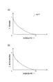
次いで、失陥経過時間t1に基づいて過渡係数k1を決定する(S74)。具体的には、図8(A)に示した失陥経過時間−過渡係数マップmp71を用いて失陥経過時間t1に対応した過渡係数k1を決定する。ここで、失陥経過時間−過渡係数マップmp71では、失陥経過時間t1が「0」の場合に過渡係数k1が「1」になり、失陥経過時間t1が減衰時間t2の場合に、過渡係数k1が「0」になる。また、失陥経過時間t1が進行して減衰時間t2に近づくに従って過渡係数k1が徐々に減少して「0」に近づく。 Next, the transient coefficient k1 is determined based on the failure elapsed time t1 (S74). Specifically, the transient coefficient k1 corresponding to the failure elapsed time t1 is determined using the failure elapsed time-transient coefficient map mp71 shown in FIG. Here, in the failure elapsed time-transient coefficient map mp71, when the failure elapsed time t1 is "0", the transient coefficient k1 is "1", and when the failure elapsed time t1 is the decay time t2, the transient The coefficient k1 becomes “0”. Further, as the failure elapsed time t1 advances and approaches the decay time t2, the transient coefficient k1 gradually decreases and approaches “0”.
図5に示すように、過渡係数k1の決定後は、その過渡係数k1と通常電流指令値Iaとの積を本発明に係る減衰過渡指令値Ibとして演算して(S75)、この減衰過渡指令値決定処理(S8)から抜ける。 As shown in FIG. 5, after the transient coefficient k1 is determined, the product of the transient coefficient k1 and the normal current command value Ia is calculated as the attenuated transient command value Ib according to the present invention (S75). Exit from the value determination process (S8).
ここで、図8(B)には、失陥経過時間t1をX軸(横軸)、減衰過渡指令値IbをY軸(縦軸)で表したグラフが示されている。ここで、減衰過渡指令値Ibは、上記の通り、過渡係数k1と通常電流指令値Iaとの積であるから、この減衰過渡指令値Ibも、過渡係数k1と同様に、失陥経過時間t1の進行と共に徐々に減少して「0」に近づく。 Here, FIG. 8B shows a graph in which the failure elapsed time t1 is represented by the X axis (horizontal axis) and the attenuation transient command value Ib is represented by the Y axis (vertical axis). Here, since the attenuation transient command value Ib is the product of the transient coefficient k1 and the normal current command value Ia as described above, the attenuation transient command value Ib is also the failure elapsed time t1 as with the transient coefficient k1. As it progresses, it gradually decreases and approaches “0”.
なお、上記した減衰過渡指令値決定処理(S8)の実行により、図7のブロック図で示した制御系における減衰過渡指令値決定部102が構成される。
Note that, by executing the above-described attenuation transient command value determination process (S8), the attenuation transient command
図2に示すように減衰過渡指令値決定処理(S8)から抜けると、減衰過渡指令値Ibの値をアシスト指令値Ixに設定し(S9)、そのアシスト指令値Ixとしての減衰過渡指令値Ibをモータ駆動回路42に付与して(S11)、操舵制御プログラムPG1から抜ける。 As shown in FIG. 2, after exiting the damping transient command value determination process (S8), the value of the damping transient command value Ib is set to the assist command value Ix (S9), and the damping transient command value Ib as the assist command value Ix is set. Is applied to the motor drive circuit 42 (S11), and the process exits the steering control program PG1.
また、上記した切り戻し判別処理(S6)による判別結果が「切り戻し有り(F1=1)」の場合には(S7:YES)、アシスト指令値Ixを「0」に設定し(S10)、そのアシスト指令値Ix(=0)をモータ駆動回路42に付与して(S11)、操舵制御プログラムPG1から抜ける。 Further, when the determination result by the above-described switchback determination process (S6) is “with switchback (F1 = 1)” (S7: YES), the assist command value Ix is set to “0” (S10), The assist command value Ix (= 0) is given to the motor drive circuit 42 (S11), and the process leaves the steering control program PG1.
なお、上記したステップS7の実行によって図7のブロック図におけるスイッチ107が構成され、ステップS10の実行によって同ブロック図におけるアシスト停止部101が構成される。そして、本実施形態では、これらステップS10とアシスト停止部101とが、本発明に係る「強制終了手段」に相当する。
Note that the execution of step S7 described above configures the
本実施形態の構成に関する説明は以上である。本実施形態の電動パワーステアリング装置11は、上記した構成により、通常は、操舵負荷トルクT1に基づいて決定された通常指令値Iaに応じてアシスト力を出力する。このとき、ハンドル33の操舵に対する路面抵抗は操舵負荷トルクT1に反映され、その操舵負荷トルクT1に基づいた通常指令値Iaを用いてアシスト力を制御するので、運転者が受ける操舵負荷トルクT1は安定する。また、通常電流指令値Iaには、車速Vが増すに従って小さくなるゲインG1が掛けられているので、高速走行時には通常電流指令値Iaが減少してハンドル33が重くなり、低速走行時には通常電流指令値Iaが増加してハンドル33が軽くなる。これにより、高速走行時に急ハンドルが防がれ、低速走行における車庫入れ等が容易になる。
This completes the description of the configuration of the present embodiment. With the above-described configuration, the electric
さて、トルクセンサ35が失陥した場合には、操舵負荷トルクT1に基づくアシスト力の制御を行うことができなくなる。そこで、本実施形態の電動パワーステアリング装置11では、トルクセンサ35の失陥時のアシスト力を、その失陥時から減衰時間t2が経過する迄の間に徐々に減衰させていく。
Now, when the
ところで、ハンドル33を切って車両10が旋回している状態では、操舵シャフト32が捻れ変形する。より具体的には、操舵シャフト32の上端部に付与されたハンドル33からの負荷トルクと、操舵シャフト32の下端部に付与されかつ電動パワーステアリング装置11のアシスト力によって軽減された路面抵抗による負荷トルクとにより捻れ変形する。そして、ハンドル33を切り戻すと、ハンドル33側の操舵シャフト32にかかっていた負荷トルクが逆向きになるので操舵シャフト32の捻れ量が激変する。即ち、操舵シャフト32の捻れ量の変化量θxが比較的大きくなる。
By the way, in a state where the
このような場合、本実施形態の電動パワーステアリング装置11の構成によれば、操舵シャフト32の捻れ量の変化量θxが、トルクセンサ35の失陥時の前後で予め定められた基準値K1を超えて大きくなったか否かに基づいて、ハンドル33の切り戻しの有無を判別することができる。そして、ハンドル33の切り戻し有りと判別したときに、アシスト指令値Ixとしてアシストモータ19に付与されていた減衰過渡指令値Ibを強制的に0にすることで、電動パワーステアリング装置11からのアシスト力の付与が停止され、そのアシスト力が切り戻し動作の妨げになる事態を防ぐことができる。これにより、トルクセンサ35の失陥後に切り戻しを行った際の違和感を従来より軽減することが可能になる。
[第2実施形態]
In such a case, according to the configuration of the electric
[Second Embodiment]
本実施形態は、前記第1実施形態に対し、操舵制御プログラムPG1の構成、特に、切り戻し判別処理(S6。図9参照)の構成が異なる。以下、図2及び図9を参照しつつ本実施形態の構成を説明する。 The present embodiment differs from the first embodiment in the configuration of the steering control program PG1, particularly in the configuration of the switchback determination process (S6, see FIG. 9). Hereinafter, the configuration of the present embodiment will be described with reference to FIGS. 2 and 9.
本実施形態の操舵制御プログラムPG1(図2参照)を実行すると、トルクセンサ35、舵角センサ34等の検出結果と共に、車両10に備えた横Gセンサ(図示せず)の検出結果も取り込まれる(S1)。また、データバッファ処理(S4)において、舵角センサ34の最新の検出値である操舵角θ1が操舵角レジスタθsに格納(記憶)されると共に、横Gセンサの最新の検出値G1が、横GレジスタGsに格納(記憶)される。
When the steering control program PG1 (see FIG. 2) of the present embodiment is executed, the detection results of the lateral G sensor (not shown) provided in the
そして、切り戻し判別処理(S6)が実行されると、図9に示すように、失陥時直前の舵角センサ34の検出値である操舵角レジスタθsの値と、舵角センサ34の現在の検出値である操舵角θ1とから、失陥時の前後に亘った操舵角の変化量θy(=θs−θ1)が求められる。また、失陥時直前の横Gセンサの検出値である横GレジスタGsの値と、横Gセンサの現在の検出値G1とから、失陥時の前後に亘った横Gの変化量Gyが求められる。
When the switchback determination process (S6) is executed, as shown in FIG. 9, the value of the steering angle register θs, which is the detected value of the
そして、切り戻しの有無の判定用のフラグF1が「1」になっていなかった場合(S21:NO)には、操舵角の変化量θyが第1基準値K2より大きく(S103:YES)、かつ、横Gの変化量Gyが第2基準値K3より小さい(S104:YES)ことを条件にしてハンドル33が切り戻されたものと判断し、フラグF1に「1」をセットしてから(S23)、この処理(S6)から抜ける。また、それ以外の場合(S103及びS104の何れかでNO)は、フラグF1を「0」に維持してこの処理(S6)から抜ける。
If the flag F1 for determining whether or not to switch back is not “1” (S21: NO), the steering angle change amount θy is larger than the first reference value K2 (S103: YES). Further, it is determined that the
ところで、ハンドル33を切って車両10が旋回している状態では、上記した操舵シャフト32のような操舵系部品が捻れ変形すると共に、車両10全体も捻れ変形する。また、ハンドル33を切り戻すと、車両10全体の捻れ量も激減する。そして、本実施形態では、車両10全体を可撓部材として捉えかつその可撓部材の一端部が操舵シャフト32であり、他端部が操舵シャフト32以外の車両本体10H(図1参照)であると捉えている。さらに、車両10の旋回によって変化する物理量としての操舵シャフト32の回転角(即ち、操舵角)と車両本体10Hに係る横Gを利用している。そして、可撓部材として捉えた車両10全体の一端部の操舵シャフト32の物理量と他端部の車両本体10Hの物理量のうち、操舵シャフト32の物理量のみがトルクセンサ35の失陥時の前後で大きく変化した場合に、車両10全体を捻れ量の変化量が基準値を超えて大きくなったと推定している。
By the way, in a state in which the
即ち、本実施形態では、操舵角の変化量θyが第1基準値K2を超えて大きくなり、かつ、横Gの変化量Gyが第2基準値K3より小さいことを条件にして、車両10全体の捻れ量の変化量が、トルクセンサ35の失陥時の前後で基準値を超えて大きくなったと推定し、ハンドル33の切り戻し有無を判別している。この構成によっても、ハンドル33の切り戻しの有無を判別することができ、ハンドル33の切り戻しが有ったときに、減衰過渡指令値Ibを強制的に0にすることで、トルクセンサ35の失陥後に切り戻しを行った際の違和感を従来より軽減することができる。
That is, in the present embodiment, the
[第3実施形態]
本実施形態は、前記第1実施形態に対し、操舵制御プログラムPG1の構成、特に、切り戻し判別処理(S6。図10参照)の構成が異なる。以下、図2及び図10を参照しつつ本実施形態の構成を説明する。
[Third Embodiment]
The present embodiment differs from the first embodiment in the configuration of the steering control program PG1, particularly in the configuration of the switchback determination process (S6, see FIG. 10). Hereinafter, the configuration of the present embodiment will be described with reference to FIGS. 2 and 10.
本実施形態では、データバッファ処理(S4)において(図2参照)、最新の操舵角θ1を操舵角レジスタθsに格納(記憶)すると共に、左右の転舵輪50,50の間の回転速度差W1(=NR−NL)を求め、その回転速度差W1の最新の値を、回転速度差レジスタWsに格納(記憶)する。
In the present embodiment, in the data buffer process (S4) (see FIG. 2), the latest steering angle θ1 is stored (stored) in the steering angle register θs, and the rotational speed difference W1 between the left and right steered
また、切り戻し判別処理(S6)においては、図10に示すように、第2実施形態と同様に操舵角の変化量θy(=θs−θ1)を求めると共に、回転速度差レジスタWsの値と、現時点の回転速度差W1とから、失陥時の前後に亘った左右の転舵輪50,50の間の回転速度差の変化量Wy(=Ws−W1)を求める(S111)。そして、切り戻しの有無の判定用のフラグF1が「1」になっていなかった場合に(S21:NO)、操舵角の変化量θyが第1基準値K2より大きいく(S103:YES)、かつ、回転速度差の変化量Wyが第3基準値K4より小さい(S114:YES)ことを条件にしてハンドル33が切り戻されたものと判断し、フラグF1に「1」をセットしてから(S23)、この処理(S6)から抜ける。それ以外の場合(S103及びS114の何れかでNO)は、フラグF1を「0」に維持してこの処理(S6)から抜ける。
In the switchback determination process (S6), as shown in FIG. 10, the change amount θy (= θs−θ1) of the steering angle is obtained and the value of the rotational speed difference register Ws is obtained as in the second embodiment. Then, a change amount Wy (= Ws−W1) of the rotational speed difference between the left and right steered
このように本実施形態では、車両10全体を可撓部材として捉えかつその可撓部材の一端部が操舵シャフト32であり、他端部が転舵輪50,50(図1参照)であると捉えている。また、車両10の旋回によって変化する物理量としての操舵シャフト32の回転角(即ち、操舵角)と左右の転舵輪50,50の内外輪差を利用している。そして、トルクセンサ35の失陥時の前後で、操舵角の変化量θyが第1基準値K2を超えて大きくなり、かつ、左右の転舵輪50,50の回転速度差の変化量Wyが、第3基準値K4より小さいことを条件にして、車両10全体の捻れ量の変化量が、トルクセンサ35の失陥時の前後で基準値を超えて大きくなったと推定し、ハンドル33の切り戻し有無を判別している。
[第4実施形態]
Thus, in the present embodiment, the
[Fourth Embodiment]
本実施形態は、前記第1実施形態に対し、操舵制御プログラムPG1の構成、特に、切り戻し判別処理(S6。図11参照)の構成が異なる。以下、図2及び図11を参照しつつ本実施形態の構成を説明する。 The present embodiment differs from the first embodiment in the configuration of the steering control program PG1, particularly in the configuration of the switchback determination process (S6, see FIG. 11). Hereinafter, the configuration of the present embodiment will be described with reference to FIGS. 2 and 11.
本実施形態の操舵制御プログラムPG1(図2参照)を実行すると、トルクセンサ35、舵角センサ34等の検出結果と共に、車両10のヨーレートR1が取り込まれる。また、データバッファ処理(S4)において、最新の操舵角θ1が操舵角レジスタθsに格納(記憶)されると共に、最新のヨーレートR1がヨーレートレジスタRsに格納(記憶)される。
When the steering control program PG1 (see FIG. 2) of the present embodiment is executed, the yaw rate R1 of the
そして、切り戻し判別処理(S6)が実行されると、図11に示すように、第2実施形態と同様に失陥時の前後に亘った操舵角の変化量θy(=θs−θ1)が求められると共に、失陥時の前後に亘ったヨーレートの変化量Ry(=Rs−R1)が求められる(S121)。そして、切り戻しの有無の判定用のフラグF1が「1」になっていなかった場合に(S21:NO)、操舵角の変化量θyが第1基準値K2より大きく(S103:YES)、かつ、ヨーレートの変化量Ryが第4基準値K5より小さい(S124:YES)ことを条件にしてハンドル33が切り戻されたものと判断し、フラグF1に「1」をセットしてから(S23)、この処理(S6)から抜ける。それ以外の場合(S103及びS124の何れかでNO)は、フラグF1を「0」に維持してこの処理(S6)から抜ける。
When the switchback determination process (S6) is executed, as shown in FIG. 11, the change amount θy (= θs−θ1) of the steering angle before and after the failure occurs as in the second embodiment. In addition to being obtained, a change amount Ry (= Rs−R1) of the yaw rate before and after the failure is obtained (S121). When the flag F1 for determining whether or not to switch back is not “1” (S21: NO), the steering angle change amount θy is larger than the first reference value K2 (S103: YES), and Then, it is determined that the
このように本実施形態では、車両10全体を可撓部材として捉えかつその可撓部材の一端部が操舵シャフト32であり、他端部が車両本体10H(図1参照)であると捉えている。また、車両10の旋回によって変化する物理量としての操舵シャフト32の回転角(即ち、操舵角)とヨーレートを利用している。そして、トルクセンサ35の失陥時の前後で、操舵角の変化量θyが第1基準値K2を超えて大きくなり、かつ、ヨーレートの変化量Ryが、第4基準値K5より小さいことを条件にして、車両10全体の捻れ量の変化量が、トルクセンサ35の失陥時の前後で基準値を超えて大きくなったと推定し、ハンドル33の切り戻し有無を判別している。
Thus, in the present embodiment, the
本発明は、前記実施形態に限定されるものではなく、上記以外にも要旨を逸脱しない範囲内で種々変更して実施することができる。 The present invention is not limited to the above-described embodiment, and can be implemented with various modifications other than those described above without departing from the scope of the invention.
10 車両(可撓部材)
10H 車両本体
11 電動パワーステアリング装置
16 転舵シャフト
19 アシストモータ
25 モータ回転位置センサ
32 操舵シャフト(可撓部材)
33 ハンドル
34 舵角センサ
35 トルクセンサ
36L,36R 回転速度センサ
50 転舵輪
100 通常指令値決定部
101 アシスト停止部
102 減衰過渡指令値決定部
103 判別部
107 スイッチ
108 スイッチ
109 トルクセンサ失陥判別部
Ia 通常電流指令値(通常指令値)
Ib 減衰過渡指令値
Ix アシスト指令値
K1 基準値
K2 第1基準値
K3 第2基準値
K4 第3基準値
K5 第4基準値
PG1 操舵制御プログラム
10 Vehicle (flexible member)
33
Ib Decay transient command value Ix Assist command value K1 Reference value K2 First reference value K3 Second reference value K4 Third reference value K5 Fourth reference value PG1 Steering control program
Claims (5)
前記ハンドルの操舵に対する操舵負荷トルクを検出するためのトルクセンサと、
前記トルクセンサが検出した前記操舵負荷トルクに基づいて前記アシスト指令値としての通常指令値を決定する通常指令値決定手段と、
前記トルクセンサが失陥した場合に、予め定められた減衰時間に亘って、失陥時直前の前記通常指令値から徐々に0へと減衰する減衰過渡指令値を前記アシスト指令値として生成する減衰過渡指令値生成手段と、
前記ハンドルの切り戻しの有無を判別する切り戻し判別手段と、
前記減衰過渡指令値が0に至る前に、前記ハンドルの切り戻し有りと判別されたときに、前記減衰過渡指令値を強制的に0にする強制終了手段とを備え、
前記切り戻し判別手段は、前記車両の旋回時に捻れ変形する可撓部材の捻れ量の変化量が、前記トルクセンサの失陥時の前後で予め定められた基準値を超えて大きくなったときに、前記ハンドルの切り戻し有りと判別するように構成されたことを特徴とする電動パワーステアリング装置。 An electric power steering device that drives a motor based on an assist command value determined according to a driving situation of a vehicle and outputs an assist force for assisting steering of a steering wheel,
A torque sensor for detecting a steering load torque for steering the steering wheel;
Normal command value determining means for determining a normal command value as the assist command value based on the steering load torque detected by the torque sensor;
Attenuation that generates, as the assist command value, a damping transient command value that gradually decays from the normal command value immediately before the failure to zero over a predetermined decay time when the torque sensor fails. A transient command value generating means;
Switchback determining means for determining whether or not the handle is switched back;
Forcibly terminating means for forcibly setting the damping transient command value to 0 when it is determined that the steering wheel is turned back before the damping transient command value reaches 0,
The switch-back determining means is configured such that when the amount of change in the amount of twist of the flexible member that twists and deforms when the vehicle turns exceeds a predetermined reference value before and after the failure of the torque sensor. The electric power steering apparatus is configured to determine that the steering wheel is turned back.
前記切り戻し判別手段は、前記舵角センサ及び前記モータ回転位置センサの検出結果に基づいて前記可撓部材としての前記操舵シャフトの捻れ量の変化量を検出することを特徴とする請求項1に記載の電動パワーステアリング装置。 A steering angle sensor that is attached to a steering shaft that rotates together with the handle and detects a steering angle of the handle, and a motor rotation position sensor for detecting an output rotation angle of the motor,
The switchback determination means detects a change amount of a twist amount of the steering shaft as the flexible member based on detection results of the steering angle sensor and the motor rotational position sensor. The electric power steering apparatus as described.
前記車両にかかる横Gを検出するための横Gセンサとを備え、
前記切り戻し判別手段は、前記トルクセンサの失陥時の前後で、前記操舵角の変化量が予め定められた第1基準値を超えて大きくなり、かつ、前記横Gの変化量が予め定められた第2基準値より小さいことを条件にして、前記可撓部材としての前記車両全体の前記捻れ量の変化量が、前記トルクセンサの失陥時の前後で前記基準値を超えて大きくなったと推定することを特徴とする請求項1又は2に記載の電動パワーステアリング装置。 A steering angle sensor that is attached to a steering shaft that rotates with the handle and detects the steering angle of the handle;
A lateral G sensor for detecting the lateral G applied to the vehicle,
The switchback determining means has a change amount of the steering angle that exceeds a predetermined first reference value before and after the failure of the torque sensor, and a change amount of the lateral G is determined in advance. The amount of change in the torsion amount of the entire vehicle as the flexible member is larger than the reference value before and after the failure of the torque sensor, on condition that the second reference value is smaller than the second reference value. The electric power steering apparatus according to claim 1, wherein the electric power steering apparatus is estimated.
前記車両に備えた左右の車輪の回転速度を検出可能な回転速度センサとを備え、
前記切り戻し判別手段は、前記トルクセンサの失陥時の前後で、前記操舵角の変化量が予め定められた第1基準値を超えて大きくなり、かつ、前記左右の車輪の回転速度差の変化量が、予め定められた第3基準値より小さいことを条件にして、前記可撓部材としての前記車両全体の前記捻れ量の変化量が、前記トルクセンサの失陥時の前後で前記基準値を超えて大きくなったと推定することを特徴とする請求項1乃至3の何れかに記載の電動パワーステアリング装置。 A steering angle sensor that is attached to a steering shaft that rotates with the handle and detects the steering angle of the handle;
A rotational speed sensor capable of detecting rotational speeds of left and right wheels provided in the vehicle,
The switch-back determination means increases the amount of change in the steering angle before and after the failure of the torque sensor exceeding a predetermined first reference value, and detects the difference in rotational speed between the left and right wheels. On the condition that the amount of change is smaller than a predetermined third reference value, the amount of change in the torsion amount of the entire vehicle as the flexible member is the reference value before and after the failure of the torque sensor. The electric power steering apparatus according to any one of claims 1 to 3, wherein the electric power steering apparatus is estimated to be larger than a value.
前記車両のヨーレートを検出するヨーレート検出部とを備え、
前記切り戻し判別手段は、前記トルクセンサの失陥時の前後で、前記操舵角の変化量が予め定められた第1基準値を超えて大きくなり、かつ、前記ヨーレートの変化量が、予め定められた第4基準値より小さいことを条件にして、前記可撓部材としての前記車両全体の前記捻れ量の変化量が、前記トルクセンサの失陥時の前後で前記基準値を超えて大きくなったと推定することを特徴とする請求項1乃至4の何れかに記載の電動パワーステアリング装置。 A steering angle sensor that is attached to a steering shaft that rotates with the handle and detects the steering angle of the handle;
A yaw rate detector for detecting the yaw rate of the vehicle,
The switchback determining means has a change amount of the steering angle that exceeds a predetermined first reference value before and after the failure of the torque sensor, and a change amount of the yaw rate is determined in advance. The amount of change in the torsion amount of the entire vehicle as the flexible member becomes larger than the reference value before and after the failure of the torque sensor, on condition that it is smaller than the fourth reference value. The electric power steering apparatus according to any one of claims 1 to 4, wherein the electric power steering apparatus is estimated.
Priority Applications (1)
| Application Number | Priority Date | Filing Date | Title |
|---|---|---|---|
| JP2007122296A JP2008273473A (en) | 2007-05-07 | 2007-05-07 | Electric power steering device |
Applications Claiming Priority (1)
| Application Number | Priority Date | Filing Date | Title |
|---|---|---|---|
| JP2007122296A JP2008273473A (en) | 2007-05-07 | 2007-05-07 | Electric power steering device |
Publications (1)
| Publication Number | Publication Date |
|---|---|
| JP2008273473A true JP2008273473A (en) | 2008-11-13 |
Family
ID=40052000
Family Applications (1)
| Application Number | Title | Priority Date | Filing Date |
|---|---|---|---|
| JP2007122296A Pending JP2008273473A (en) | 2007-05-07 | 2007-05-07 | Electric power steering device |
Country Status (1)
| Country | Link |
|---|---|
| JP (1) | JP2008273473A (en) |
Cited By (1)
| Publication number | Priority date | Publication date | Assignee | Title |
|---|---|---|---|---|
| CN105667584A (en) * | 2014-12-03 | 2016-06-15 | 株式会社电装 | Control apparatus |
Citations (5)
| Publication number | Priority date | Publication date | Assignee | Title |
|---|---|---|---|---|
| JPH0958505A (en) * | 1995-08-30 | 1997-03-04 | Jidosha Kiki Co Ltd | Motor-driven power steering device |
| JPH1178937A (en) * | 1997-09-03 | 1999-03-23 | Honda Motor Co Ltd | Electric power steering device |
| JP2000238652A (en) * | 1999-02-19 | 2000-09-05 | Denso Corp | Electric power steering device |
| JP2001018823A (en) * | 1999-07-09 | 2001-01-23 | Nissan Motor Co Ltd | Vehicle steering system |
| JP2002019632A (en) * | 2000-07-06 | 2002-01-23 | Nissan Motor Co Ltd | Lane following cruise control device |
-
2007
- 2007-05-07 JP JP2007122296A patent/JP2008273473A/en active Pending
Patent Citations (5)
| Publication number | Priority date | Publication date | Assignee | Title |
|---|---|---|---|---|
| JPH0958505A (en) * | 1995-08-30 | 1997-03-04 | Jidosha Kiki Co Ltd | Motor-driven power steering device |
| JPH1178937A (en) * | 1997-09-03 | 1999-03-23 | Honda Motor Co Ltd | Electric power steering device |
| JP2000238652A (en) * | 1999-02-19 | 2000-09-05 | Denso Corp | Electric power steering device |
| JP2001018823A (en) * | 1999-07-09 | 2001-01-23 | Nissan Motor Co Ltd | Vehicle steering system |
| JP2002019632A (en) * | 2000-07-06 | 2002-01-23 | Nissan Motor Co Ltd | Lane following cruise control device |
Cited By (2)
| Publication number | Priority date | Publication date | Assignee | Title |
|---|---|---|---|---|
| CN105667584A (en) * | 2014-12-03 | 2016-06-15 | 株式会社电装 | Control apparatus |
| JP2016107711A (en) * | 2014-12-03 | 2016-06-20 | 株式会社デンソー | Control device |
Similar Documents
| Publication | Publication Date | Title |
|---|---|---|
| US9308934B2 (en) | Steering control system for vehicle and steering control method for vehicle | |
| JP5962312B2 (en) | Electric power steering control device | |
| KR100803411B1 (en) | Steering Control Device and Method | |
| US7628247B2 (en) | Electric power steering device equipped with automatic steering function | |
| JP7099892B2 (en) | Steering control device | |
| US20190210638A1 (en) | Vehicle Control System, Vehicle Control Method, and Electric Power Steering System | |
| JP2003175850A (en) | Control device for electric power steering device | |
| CN102666255B (en) | Determination of a center feeling for EPS steering systems | |
| KR20060031700A (en) | Stabilizer Control Unit | |
| JP2009220735A (en) | Electric power steering device | |
| JP5174596B2 (en) | Electric power steering device | |
| JP4341632B2 (en) | Stabilizer control device | |
| JP2004338562A (en) | Electric power steering control device | |
| US9884642B2 (en) | Steering device | |
| JP2009057017A (en) | Electric power steering device | |
| JP4449790B2 (en) | Electric power steering device | |
| JP2008273473A (en) | Electric power steering device | |
| JP2008296829A (en) | Electric power steering device | |
| JPS62241768A (en) | Power steering device | |
| JP5152470B2 (en) | Electric power steering device | |
| JP2007071784A (en) | Torque detection device | |
| JP2012056402A (en) | Motor-driven power steering device | |
| JP2014227104A (en) | Power-assisted steering device | |
| JP4678467B2 (en) | Power steering device | |
| JP5130685B2 (en) | Electric power steering device |
Legal Events
| Date | Code | Title | Description |
|---|---|---|---|
| A621 | Written request for application examination |
Free format text: JAPANESE INTERMEDIATE CODE: A621 Effective date: 20100414 |
|
| A977 | Report on retrieval |
Free format text: JAPANESE INTERMEDIATE CODE: A971007 Effective date: 20120327 |
|
| A131 | Notification of reasons for refusal |
Free format text: JAPANESE INTERMEDIATE CODE: A131 Effective date: 20120404 |
|
| A02 | Decision of refusal |
Free format text: JAPANESE INTERMEDIATE CODE: A02 Effective date: 20120822 |