JP2008520175A - 永久磁石回転子 - Google Patents
永久磁石回転子 Download PDFInfo
- Publication number
- JP2008520175A JP2008520175A JP2007540552A JP2007540552A JP2008520175A JP 2008520175 A JP2008520175 A JP 2008520175A JP 2007540552 A JP2007540552 A JP 2007540552A JP 2007540552 A JP2007540552 A JP 2007540552A JP 2008520175 A JP2008520175 A JP 2008520175A
- Authority
- JP
- Japan
- Prior art keywords
- rotor
- permanent magnet
- groove
- module
- modules
- Prior art date
- Legal status (The legal status is an assumption and is not a legal conclusion. Google has not performed a legal analysis and makes no representation as to the accuracy of the status listed.)
- Granted
Links
- 230000002093 peripheral effect Effects 0.000 claims description 36
- 238000004080 punching Methods 0.000 claims description 14
- 238000000034 method Methods 0.000 claims description 13
- 239000004020 conductor Substances 0.000 claims description 12
- 238000004519 manufacturing process Methods 0.000 claims description 10
- 239000000463 material Substances 0.000 claims description 3
- 230000004323 axial length Effects 0.000 claims description 2
- 239000007787 solid Substances 0.000 claims description 2
- 230000007704 transition Effects 0.000 abstract description 9
- 230000004907 flux Effects 0.000 description 10
- BGPVFRJUHWVFKM-UHFFFAOYSA-N N1=C2C=CC=CC2=[N+]([O-])C1(CC1)CCC21N=C1C=CC=CC1=[N+]2[O-] Chemical compound N1=C2C=CC=CC2=[N+]([O-])C1(CC1)CCC21N=C1C=CC=CC1=[N+]2[O-] BGPVFRJUHWVFKM-UHFFFAOYSA-N 0.000 description 9
- 238000009413 insulation Methods 0.000 description 6
- 238000010586 diagram Methods 0.000 description 3
- RYGMFSIKBFXOCR-UHFFFAOYSA-N Copper Chemical compound [Cu] RYGMFSIKBFXOCR-UHFFFAOYSA-N 0.000 description 2
- 230000008901 benefit Effects 0.000 description 2
- 230000008859 change Effects 0.000 description 2
- 238000010276 construction Methods 0.000 description 2
- 229910052802 copper Inorganic materials 0.000 description 2
- 239000010949 copper Substances 0.000 description 2
- 239000000696 magnetic material Substances 0.000 description 2
- 239000002184 metal Substances 0.000 description 2
- 229910052751 metal Inorganic materials 0.000 description 2
- 230000008569 process Effects 0.000 description 2
- 230000015572 biosynthetic process Effects 0.000 description 1
- 238000005266 casting Methods 0.000 description 1
- 230000008878 coupling Effects 0.000 description 1
- 238000010168 coupling process Methods 0.000 description 1
- 238000005859 coupling reaction Methods 0.000 description 1
- 230000007423 decrease Effects 0.000 description 1
- 230000001419 dependent effect Effects 0.000 description 1
- 238000006073 displacement reaction Methods 0.000 description 1
- 238000009499 grossing Methods 0.000 description 1
- 230000000149 penetrating effect Effects 0.000 description 1
Images




Classifications
-
- H—ELECTRICITY
- H02—GENERATION; CONVERSION OR DISTRIBUTION OF ELECTRIC POWER
- H02K—DYNAMO-ELECTRIC MACHINES
- H02K15/00—Processes or apparatus specially adapted for manufacturing, assembling, maintaining or repairing of dynamo-electric machines
- H02K15/02—Processes or apparatus specially adapted for manufacturing, assembling, maintaining or repairing of dynamo-electric machines of stator or rotor bodies
- H02K15/03—Processes or apparatus specially adapted for manufacturing, assembling, maintaining or repairing of dynamo-electric machines of stator or rotor bodies having permanent magnets
-
- H—ELECTRICITY
- H02—GENERATION; CONVERSION OR DISTRIBUTION OF ELECTRIC POWER
- H02K—DYNAMO-ELECTRIC MACHINES
- H02K1/00—Details of the magnetic circuit
- H02K1/06—Details of the magnetic circuit characterised by the shape, form or construction
- H02K1/22—Rotating parts of the magnetic circuit
- H02K1/27—Rotor cores with permanent magnets
- H02K1/2706—Inner rotors
- H02K1/272—Inner rotors the magnetisation axis of the magnets being perpendicular to the rotor axis
- H02K1/274—Inner rotors the magnetisation axis of the magnets being perpendicular to the rotor axis the rotor consisting of two or more circumferentially positioned magnets
- H02K1/2753—Inner rotors the magnetisation axis of the magnets being perpendicular to the rotor axis the rotor consisting of two or more circumferentially positioned magnets the rotor consisting of magnets or groups of magnets arranged with alternating polarity
- H02K1/276—Magnets embedded in the magnetic core, e.g. interior permanent magnets [IPM]
-
- H—ELECTRICITY
- H02—GENERATION; CONVERSION OR DISTRIBUTION OF ELECTRIC POWER
- H02K—DYNAMO-ELECTRIC MACHINES
- H02K1/00—Details of the magnetic circuit
- H02K1/06—Details of the magnetic circuit characterised by the shape, form or construction
- H02K1/22—Rotating parts of the magnetic circuit
- H02K1/27—Rotor cores with permanent magnets
- H02K1/2706—Inner rotors
- H02K1/272—Inner rotors the magnetisation axis of the magnets being perpendicular to the rotor axis
- H02K1/274—Inner rotors the magnetisation axis of the magnets being perpendicular to the rotor axis the rotor consisting of two or more circumferentially positioned magnets
- H02K1/2753—Inner rotors the magnetisation axis of the magnets being perpendicular to the rotor axis the rotor consisting of two or more circumferentially positioned magnets the rotor consisting of magnets or groups of magnets arranged with alternating polarity
- H02K1/276—Magnets embedded in the magnetic core, e.g. interior permanent magnets [IPM]
- H02K1/2766—Magnets embedded in the magnetic core, e.g. interior permanent magnets [IPM] having a flux concentration effect
- H02K1/2773—Magnets embedded in the magnetic core, e.g. interior permanent magnets [IPM] having a flux concentration effect consisting of tangentially magnetized radial magnets
-
- Y—GENERAL TAGGING OF NEW TECHNOLOGICAL DEVELOPMENTS; GENERAL TAGGING OF CROSS-SECTIONAL TECHNOLOGIES SPANNING OVER SEVERAL SECTIONS OF THE IPC; TECHNICAL SUBJECTS COVERED BY FORMER USPC CROSS-REFERENCE ART COLLECTIONS [XRACs] AND DIGESTS
- Y10—TECHNICAL SUBJECTS COVERED BY FORMER USPC
- Y10T—TECHNICAL SUBJECTS COVERED BY FORMER US CLASSIFICATION
- Y10T29/00—Metal working
- Y10T29/49—Method of mechanical manufacture
- Y10T29/49002—Electrical device making
- Y10T29/49009—Dynamoelectric machine
- Y10T29/49012—Rotor
Landscapes
- Engineering & Computer Science (AREA)
- Power Engineering (AREA)
- Manufacturing & Machinery (AREA)
- Permanent Field Magnets Of Synchronous Machinery (AREA)
- Iron Core Of Rotating Electric Machines (AREA)
- Organic Low-Molecular-Weight Compounds And Preparation Thereof (AREA)
Abstract
【解決手段】回転子の内部に該回転子の回転軸(X)に平行に延びて設けられた複数の永久磁石(4)と、複数の永久磁石(4)の半径方向外側の長手縁部(8)領域にて、回転子の外周面に外側に開いて形成され、隣接する永久磁石(4)の長手縁部に対して円周方向に傾いて又は湾曲して延びて形成された複数の溝と、を備え、溝(6)は、そのいずれの中心線も、隣接する永久磁石(4)の長手縁部(8)と少なくとも1回交差し、回転子の周面における円周方向の幅が半径方向内部に位置する領域の幅よりも狭く、横断面形状が回転子の全長にわたって一定である、ことを特徴とするものである。
【選択図】図1
Description
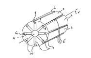
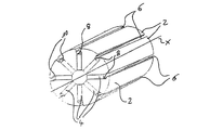
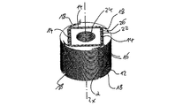
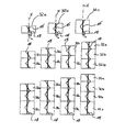
図1に示す回転子は、八個の同一な回転子セグメント2から構成され、この回転子セグメントは、例えば焼結金属部品として製造される。回転子セグメント2は、円錐形として形成され、交互に180°向きを変えている。従って、常に、回転子エレメントは、その幅が広い方の終端面が、隣接する二つの回転子エレメント2の幅が狭い方の終端面の間に位置することになる。回転子セグメント2は、夫々互いに隣接して配置されているので、回転子セグメント2の間には、半径方向に延びるフリースペースが形成され、このフリースペースに永久磁石4が配設される。永久磁石4は半径方向に延びており、従って全体としては放射状に配設されることになる。この場合、永久磁石4は、半径方向にて回転子の外周面までは延びていない。むしろ、回転子セグメント2間のフリースペースは、永久磁石4の半径方向の延長上に溝6を形成し、この溝が回転子の外周面に向かって開いている。溝6は、外周面において、回転子6の回転軸Xに沿って回転子の全長にわたり一定の隙間幅を有している。さらに、この溝6は、回転子の円周面上を斜めに延びているので、永久磁石4の半径方向外側の長手縁部8に対して斜めに延びることになる。従って、溝6は、回転子の周面上を循環するように、又は8の字状に延びている。この斜めの溝6は、回転子セグメント2を円錐形に形成することによって得られる。即ち、回転子セグメント2は、長手方向の一方の端部の横断面が、長手方向の反対側の端部におけるよりも小さくされている。
4 永久磁石
6 溝
8 長手縁部
10 拡幅部
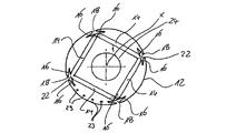
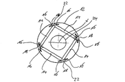
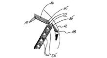
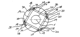
12 回転子積層板
14 スロット
16 縁部又は長手縁部
18 溝
20 空隙
22 フリースペース
23 通路
24 穴
26 結合ウェブ
28 切り欠き
30 切り欠き
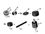
32 回転子モジュール
34 回転軸
36 永久磁石片
38 カバーディスク
X 回転軸
a 溝幅
b 間隔
α 傾き角度
Claims (19)
- モーター用の永久磁石回転子であって、
前記回転子の内部に該回転子の回転軸(X)に平行に延びて設けられた複数の永久磁石(4,36)と、
前記複数の永久磁石(4,36)の半径方向外側の長手縁部(8,16)領域にて、前記回転子の外周面に外側に開いて形成され、隣接する前記永久磁石(4,36)の長手縁部に対して円周方向に傾いて又は湾曲して延びて形成された複数の溝と、を備え、
前記溝(6,18)は、そのいずれの中心線も、隣接する前記永久磁石(4,36)の長手縁部(8,16)と少なくとも1回交差し、前記回転子の周面における円周方向の幅が半径方向内部に位置する領域の幅よりも狭く、横断面形状が前記回転子の全長にわたって一定である、
ことを特徴とする永久磁石回転子。 - 前記回転子は、内部に複数の永久磁石片(36)を配設し、周面に複数の部分溝(6,18)を設けて事前に製造された少なくとも二つの回転子モジュール(32)を、個々の回転子モジュール(32)の前記部分溝(6,18)が共同して前記溝(6,18)を形成し、個々の回転子モジュールの前記永久磁石片(36)が共同して前記永久磁石(4)を形成するように長手方向(X)に互いに組み合わせて接合したものであることを特徴とする請求項1記載の永久磁石回転子。
- 前記各回転子モジュール(32)の前記部分溝(6,18)は、隣接する前記永久磁石片(36)の長手縁部(8,16)に対して傾けて、且つ前記回転子モジュール(32)の両端面において溝の中心線が前記永久磁石片(36)の長手縁部(8,16)から円周方向にそれぞれ予め設定された同じ間隔(b)を取るように形成されたことを特徴とする請求項2記載の永久磁石回転子。
- 前記部分溝(6,18)の中心線は、隣接する前記永久磁石片(36)の長手縁部(8,16)と少なくとも1回交差することを特徴とする請求項2又は3記載の永久磁石回転子。
- 前記少なくとも二つの回転子モジュール(32)は、前記回転軸(X)方向の長さが異なることを特徴とする請求項2〜4のいずれか1項に記載の永久磁石回転子。
- 前記回転子モジュール(32)の少なくとも一つは、該回転子モジュール(32)の相対する終端面において、前記部分溝(6,18)の中心線が前記永久磁石(4,36)の長手縁部(8,16)から円周の同一方向に同じ間隔となるように傾いた部分溝(6,18)を備えていることを特徴とする請求項2〜5のいずれか1項に記載の永久磁石回転子。
- 前記溝(6,18)又は部分溝(6,18)は、隣接する前記永久磁石(4)又は永久磁石片(36)の長手縁部(8,16)に対してジグザグ状に延びていることを特徴とする請求項1〜6のいずれか1項に記載の永久磁石回転子。
- 前記各溝(6,18)は、回転子全長(X)にわたって、隣接する前記永久磁石(4,36)の少なくとも長手縁部(8,16)を半径方向にほぼ覆うように形成されたことを特徴とする請求項1〜7のいずれか1項に記載の永久磁石回転子。
- 前記溝(6,18)は、隣接する二つの前記永久磁石(4,36)の半径方向外側の長手縁部(8,16)を半径方向に覆うように形成されたことを特徴とする請求項1〜8のいずれか1項に記載の永久磁石回転子。
- 前記溝(6,18)は、燕尾形の横断面を有することを特徴とする請求項1〜9のいずれか1項に記載の永久磁石回転子。
- 前記永久磁石(4,36)の長手縁部(8,16)に隣接して、隣接する前記溝(6,18)に結合したフリースペース(22,28)を回転子の周囲材料に形成したことを特徴とする請求項1〜10のいずれか1項に記載の永久磁石回転子。
- 前記フリースペース(22,28)は、積層されて前記回転子を形成する多数の回転子積層板(12)のうち一部の回転子積層板に、隣接する前記二つの永久磁石(4,36)の間に位置して形成されたことを特徴とする請求項11記載の永久磁石回転子
- 前記回転子又は前記個々の回転子モジュール(32)は、多数の回転子積層板(12)から形成され、又は固体の若しくは焼結されたセグメント(2)を組み合わせ、互いに隣接するセグメント(2)間のスペースに前記永久磁石(4)を取り付けて形成されたことを特徴とする請求項1〜12のいずれか1項に記載の永久磁石回転子。
- 前記溝(6,18)の少なくとも一部分、又は追加的に前記回転子内に形成された通路(23)に電導体を配設したことを特徴とする請求項1〜13のいずれか1項に記載の永久磁石回転子。
- 回転子を多数の回転子積層板(12)を組み立てて形成する前記各請求項のいずれか1項に記載の永久磁石回転子の製造方法であって、
前記個々の回転子積層板(12)を組み立てられる順番に順次打ち抜いて形成し、
前記打ち抜き動作が終了する毎に、溝(18)打抜き用ツールを前記回転子の回転軸(X)を中心に所定の角度だけ回転し、
前記回転子の周面に永久磁石(4,36)の長手縁部(16)に対して傾いた溝(18)を形成し、
前記回転子積層板(12)を組み立てて回転子とした後、該回転子の長さに適合した永久磁石(4、36)を前記回転子の中に挿入する、
ことを特徴とする永久磁石回転子の製造方法。 - 前記回転子は、多数の回転子積層板を組み立てて事前に製造された少なくとも二つの回転子モジュール(32)を組み立てたものであり、
前記回転子モジュールは、前記個々の回転子積層板(12)を組み立てられる順番に順次打ち抜いて形成し、前記打ち抜き動作が終了する毎に溝(18)打抜き用ツールを前記回転子の回転軸(X)を中心に所定の角度だけ回転し、前記回転子モジュールの外周面に永久磁石(4,36)の長手縁部(16)に対して傾いた部分溝(18)を形成し、前記回転子積層板(12)を組み立てて回転子モジュールとした後、該回転子モジュールの長さに適合した永久磁石(4、36)を前記回転子モジュールの中に挿入したものである、
ことを特徴とする請求項15記載の永久磁石回転子の製造方法。 - 異なる長さの前記回転子は、前記回転軸(X)と平行に、且つ軸方向全長にわたって延びた永久磁石片(36)と、周面に隣接する前記永久磁石片(36)の半径方向外側の長手縁部(16)に対して傾いた部分溝(18)と、を備えた所定長さの複数の回転子モジュール(32)を事前に製造し、前記回転子の要求長さに応じて異なる個数の前記回転子モジュール(32)を、個々の回転子モジュール(32)の永久磁石片(36)が共同して前記回転子内に軸方向に延びた永久磁石を形成するように長手方向(X)に互いに接合して形成されることを特徴とする請求項16記載の永久磁石回転子の製造方法。
- モジュール長さの異なる少なくとも2タイプ、若しくは3タイプの前記回転子モジュール(32)を用いることを特徴とする請求項17記載の永久磁石回転子の製造方法。
- 第2タイプの回転子モジュール(32b)が第1タイプの回転子モジュール(32a)のモジュール長さよりも、その半分だけ長いモジュール長さを有し、さらに第3タイプの回転子モジュール(32c)が形成されるときには、該第3タイプの回転子モジュールは、前記第1タイプの回転子モジュール(32a)のモジュール長さの2倍の長さを有するものとしたことを特徴とする請求項18記載の永久磁石回転子の製造方法。
Applications Claiming Priority (3)
| Application Number | Priority Date | Filing Date | Title |
|---|---|---|---|
| EP04026962.3 | 2004-11-12 | ||
| EP04026962A EP1657800B1 (de) | 2004-11-12 | 2004-11-12 | Permanentmagnet-Rotor |
| PCT/EP2005/011870 WO2006050884A1 (de) | 2004-11-12 | 2005-11-07 | Permanentmagnet-rotor |
Publications (2)
| Publication Number | Publication Date |
|---|---|
| JP2008520175A true JP2008520175A (ja) | 2008-06-12 |
| JP5032994B2 JP5032994B2 (ja) | 2012-09-26 |
Family
ID=34927371
Family Applications (1)
| Application Number | Title | Priority Date | Filing Date |
|---|---|---|---|
| JP2007540552A Expired - Fee Related JP5032994B2 (ja) | 2004-11-12 | 2005-11-07 | 永久磁石回転子 |
Country Status (8)
| Country | Link |
|---|---|
| US (1) | US8067872B2 (ja) |
| EP (1) | EP1657800B1 (ja) |
| JP (1) | JP5032994B2 (ja) |
| CN (1) | CN101057381B (ja) |
| AT (1) | ATE369652T1 (ja) |
| DE (1) | DE502004004596D1 (ja) |
| RU (1) | RU2406209C2 (ja) |
| WO (1) | WO2006050884A1 (ja) |
Cited By (3)
| Publication number | Priority date | Publication date | Assignee | Title |
|---|---|---|---|---|
| JP2014217166A (ja) * | 2013-04-25 | 2014-11-17 | アイシン精機株式会社 | 超電導回転機及びその冷却方法 |
| JP2019504597A (ja) * | 2015-12-21 | 2019-02-14 | カーエスベー ソシエタス ヨーロピア ウント コンパニー コマンディート ゲゼルシャフト アウフ アクチェンKSB SE & Co. KGaA | Pmラインスタートモータ、およびそのためのスイッチオン方法 |
| JPWO2021214824A1 (ja) * | 2020-04-20 | 2021-10-28 |
Families Citing this family (32)
| Publication number | Priority date | Publication date | Assignee | Title |
|---|---|---|---|---|
| DE102007028356A1 (de) | 2007-06-15 | 2008-12-18 | Ksb Aktiengesellschaft | Permanent erregter Rotor für Arbeitsmaschinen |
| DE102007029157A1 (de) * | 2007-06-25 | 2009-01-08 | Robert Bosch Gmbh | Synchronmotor mit 12 Statorzähnen und 10 Rotorpolen |
| CN102263445B (zh) * | 2010-05-31 | 2016-07-06 | 德昌电机(深圳)有限公司 | 无刷电机 |
| CN102005838B (zh) * | 2010-10-20 | 2012-11-14 | 东元总合科技(杭州)有限公司 | 大功率永磁电机转子,该转子的安装方法及该转子永磁体的充磁方法 |
| EP2676356A1 (en) * | 2011-02-17 | 2013-12-25 | CERN - European Organization For Nuclear Research | A system and method for positioning and fixing objects relative to each other |
| US20140054985A1 (en) | 2011-02-24 | 2014-02-27 | Andritz Ritz Gmbh | Internally exicted synchronous motor comprising a permanent magnet rotor with multiple corrosion protection |
| CN102306963A (zh) * | 2011-09-14 | 2012-01-04 | 天津市松正电动汽车技术股份有限公司 | 一种永磁电机转子 |
| CN103095007A (zh) * | 2011-11-08 | 2013-05-08 | 艾默生环境优化技术(苏州)有限公司 | 转子和电动马达 |
| JP5858232B2 (ja) * | 2012-02-17 | 2016-02-10 | 日本電産株式会社 | ロータコア、モータ、およびモータの製造方法 |
| US20130249342A1 (en) * | 2012-03-20 | 2013-09-26 | Kollmorgen Corporation | Cantilevered Rotor Magnet Support |
| EP2696469B1 (de) * | 2012-08-09 | 2015-06-17 | Siemens Aktiengesellschaft | Rotor für eine permanent erregte Synchronmaschine |
| JP5877777B2 (ja) * | 2012-09-26 | 2016-03-08 | 日立オートモティブシステムズ株式会社 | 回転電機、磁極ピース製造方法 |
| US9641033B2 (en) | 2013-09-06 | 2017-05-02 | General Electric Company | Electric machine having offset rotor sections |
| US9941775B2 (en) | 2012-11-01 | 2018-04-10 | General Electric Company | D-ring implementation in skewed rotor assembly |
| US9906108B2 (en) | 2012-11-01 | 2018-02-27 | General Electric Company | Sensorless electric machine |
| US9871418B2 (en) | 2012-11-01 | 2018-01-16 | General Electric Company | Sensorless electric machine |
| DE102013005050A1 (de) * | 2013-03-22 | 2014-09-25 | Wieland-Werke Ag | Kurzschlussläufer und dessen Einzelteile sowie Verfahren zur Herstellung eines Kurzschlussläufers |
| US10069362B2 (en) * | 2013-05-07 | 2018-09-04 | Hitachi Automotive Systems, Ltd. | Structure for preventing scattering of magnet and retaining magnet for rotating electrical machine |
| US9906082B2 (en) | 2013-09-06 | 2018-02-27 | General Electric Company | Electric machine having reduced torque oscillations and axial thrust |
| NO341230B1 (en) * | 2015-11-06 | 2017-09-18 | Ateltech As | Scalable electric motor disc stack with multipole stator |
| GB2551537A (en) * | 2016-06-21 | 2017-12-27 | Jaguar Land Rover Ltd | Electrical machine |
| US11005313B2 (en) * | 2016-11-21 | 2021-05-11 | Unison Industries, Llc | Skewed rotor designs for hybrid homopolar electrical machines |
| CN111725918B (zh) * | 2018-03-16 | 2021-07-27 | 珠海格力节能环保制冷技术研究中心有限公司 | 转子结构、永磁辅助同步磁阻电机 |
| JP6791909B2 (ja) * | 2018-07-06 | 2020-11-25 | ファナック株式会社 | 磁石が接着剤にて固定された磁石埋込み型電動機のロータおよび磁石埋込み型電動機のロータの製造方法 |
| DE102018126570A1 (de) * | 2018-10-25 | 2020-04-30 | Bayerische Motoren Werke Aktiengesellschaft | Rotor |
| KR102771167B1 (ko) * | 2019-03-28 | 2025-02-24 | 엘지이노텍 주식회사 | 모터 |
| TWI693777B (zh) * | 2019-07-02 | 2020-05-11 | 東元電機股份有限公司 | 永磁馬達轉子組裝治具及其方法 |
| CN114303302B (zh) * | 2019-08-26 | 2023-12-05 | 日本电产株式会社 | 永磁铁埋入型马达 |
| DE102020111679A1 (de) * | 2020-04-29 | 2021-11-04 | Valeo Siemens Eautomotive Germany Gmbh | Welle, Umformwerkzeug, Herstellungsverfahren und Rotor für eine elektrische Maschine |
| SE545089C2 (en) * | 2020-08-11 | 2023-03-28 | Scania Cv Ab | Rotor and electrical machine |
| US20220311294A1 (en) * | 2021-03-25 | 2022-09-29 | Nidec Motor Corporation | Rotor with arcuate magnets |
| US20240243628A1 (en) * | 2023-01-12 | 2024-07-18 | Ford Global Technologies, Llc | Molded rotor endcaps |
Citations (7)
| Publication number | Priority date | Publication date | Assignee | Title |
|---|---|---|---|---|
| JPH08298735A (ja) * | 1995-04-25 | 1996-11-12 | Fuji Electric Co Ltd | 円筒状永久磁石同期電動機 |
| JP2000139063A (ja) * | 1998-11-02 | 2000-05-16 | Meidensha Corp | 永久磁石形同期回転電機 |
| JP2000354341A (ja) * | 1999-06-08 | 2000-12-19 | Yukio Kinoshita | 磁石を用いた回転電機及び電磁機器 |
| JP2001251838A (ja) * | 2000-03-06 | 2001-09-14 | Genesis:Kk | ベーシックファクターを用いた回転機 |
| JP2003153472A (ja) * | 2001-08-30 | 2003-05-23 | Yukio Kinoshita | 回転電機及び電磁機器 |
| JP2003319582A (ja) * | 2002-04-19 | 2003-11-07 | Yaskawa Electric Corp | Acサーボモータ |
| JP2004048912A (ja) * | 2002-07-12 | 2004-02-12 | Hitachi Industrial Equipment Systems Co Ltd | 永久磁石式回転電機およびそれを用いた圧縮機 |
Family Cites Families (12)
| Publication number | Priority date | Publication date | Assignee | Title |
|---|---|---|---|---|
| SU1399861A1 (ru) * | 1986-10-02 | 1988-05-30 | Всесоюзный Научно-Исследовательский,Проектно-Конструкторский И Технологический Институт Релестроения | Способ сборки ротора синхронного двигател с посто нными магнитами |
| SU1661920A1 (ru) * | 1987-11-02 | 1991-07-07 | Предприятие П/Я М-5374 | Способ изготовлени шихтованных магнитопроводов электрических машин |
| DE69333946T2 (de) * | 1992-08-12 | 2006-08-31 | Seiko Epson Corp. | Dauermagnetrotor für bürstenloser Elektromotor und Verfahren zur Herstellung |
| US5679995A (en) * | 1992-08-12 | 1997-10-21 | Seiko Epson Corporation | Permanent magnet rotor of brushless motor |
| JPH08223831A (ja) * | 1995-02-10 | 1996-08-30 | Toshiba Corp | 回転電機用の鉄心および回転子鉄心 |
| JP3493865B2 (ja) * | 1995-12-27 | 2004-02-03 | アイシン・エィ・ダブリュ株式会社 | モータ |
| DE19933009A1 (de) * | 1998-07-24 | 2000-02-10 | Matsushita Electric Industrial Co Ltd | Motor mit interne Permanentmagneten enthaltendem Rotor und einen solchen Motor verwendende Antriebseinheit |
| JP2000278895A (ja) * | 1999-03-26 | 2000-10-06 | Nissan Motor Co Ltd | 電動機のロータ |
| RU2178615C1 (ru) * | 2000-08-02 | 2002-01-20 | Новосибирский государственный технический университет | Ротор электрической машины |
| DE10203796A1 (de) * | 2002-01-31 | 2003-08-14 | Bosch Gmbh Robert | Stator für eine elektrische Maschine |
| FR2839211A1 (fr) * | 2002-04-29 | 2003-10-31 | Conception & Dev Michelin Sa | Machine electrique dont le rotor est specialement adapte aux hautes vitesses |
| US7057323B2 (en) * | 2003-03-27 | 2006-06-06 | Emerson Electric Co. | Modular flux controllable permanent magnet dynamoelectric machine |
-
2004
- 2004-11-12 AT AT04026962T patent/ATE369652T1/de not_active IP Right Cessation
- 2004-11-12 EP EP04026962A patent/EP1657800B1/de not_active Expired - Lifetime
- 2004-11-12 DE DE502004004596T patent/DE502004004596D1/de not_active Expired - Lifetime
-
2005
- 2005-11-07 JP JP2007540552A patent/JP5032994B2/ja not_active Expired - Fee Related
- 2005-11-07 US US11/719,168 patent/US8067872B2/en not_active Expired - Fee Related
- 2005-11-07 WO PCT/EP2005/011870 patent/WO2006050884A1/de not_active Ceased
- 2005-11-07 CN CN2005800389292A patent/CN101057381B/zh not_active Expired - Fee Related
- 2005-11-07 RU RU2007121582/07A patent/RU2406209C2/ru not_active IP Right Cessation
Patent Citations (7)
| Publication number | Priority date | Publication date | Assignee | Title |
|---|---|---|---|---|
| JPH08298735A (ja) * | 1995-04-25 | 1996-11-12 | Fuji Electric Co Ltd | 円筒状永久磁石同期電動機 |
| JP2000139063A (ja) * | 1998-11-02 | 2000-05-16 | Meidensha Corp | 永久磁石形同期回転電機 |
| JP2000354341A (ja) * | 1999-06-08 | 2000-12-19 | Yukio Kinoshita | 磁石を用いた回転電機及び電磁機器 |
| JP2001251838A (ja) * | 2000-03-06 | 2001-09-14 | Genesis:Kk | ベーシックファクターを用いた回転機 |
| JP2003153472A (ja) * | 2001-08-30 | 2003-05-23 | Yukio Kinoshita | 回転電機及び電磁機器 |
| JP2003319582A (ja) * | 2002-04-19 | 2003-11-07 | Yaskawa Electric Corp | Acサーボモータ |
| JP2004048912A (ja) * | 2002-07-12 | 2004-02-12 | Hitachi Industrial Equipment Systems Co Ltd | 永久磁石式回転電機およびそれを用いた圧縮機 |
Cited By (6)
| Publication number | Priority date | Publication date | Assignee | Title |
|---|---|---|---|---|
| JP2014217166A (ja) * | 2013-04-25 | 2014-11-17 | アイシン精機株式会社 | 超電導回転機及びその冷却方法 |
| JP2019504597A (ja) * | 2015-12-21 | 2019-02-14 | カーエスベー ソシエタス ヨーロピア ウント コンパニー コマンディート ゲゼルシャフト アウフ アクチェンKSB SE & Co. KGaA | Pmラインスタートモータ、およびそのためのスイッチオン方法 |
| US10978967B2 (en) | 2015-12-21 | 2021-04-13 | KSB SE & Co. KGaA | PM line-start motor and switch-on method therefor |
| JP7012013B2 (ja) | 2015-12-21 | 2022-01-27 | カーエスベー ソシエタス ヨーロピア ウント コンパニー コマンディート ゲゼルシャフト アウフ アクチェン | Pmラインスタートモータ、およびそのためのスイッチオン方法 |
| JPWO2021214824A1 (ja) * | 2020-04-20 | 2021-10-28 | ||
| JP7433419B2 (ja) | 2020-04-20 | 2024-02-19 | 三菱電機株式会社 | ロータ、モータ、圧縮機、空気調和装置およびロータの製造方法 |
Also Published As
| Publication number | Publication date |
|---|---|
| CN101057381B (zh) | 2010-09-15 |
| JP5032994B2 (ja) | 2012-09-26 |
| US20090127961A1 (en) | 2009-05-21 |
| RU2007121582A (ru) | 2008-12-20 |
| US8067872B2 (en) | 2011-11-29 |
| DE502004004596D1 (de) | 2007-09-20 |
| RU2406209C2 (ru) | 2010-12-10 |
| CN101057381A (zh) | 2007-10-17 |
| WO2006050884A1 (de) | 2006-05-18 |
| EP1657800B1 (de) | 2007-08-08 |
| EP1657800A1 (de) | 2006-05-17 |
| ATE369652T1 (de) | 2007-08-15 |
Similar Documents
| Publication | Publication Date | Title |
|---|---|---|
| JP5032994B2 (ja) | 永久磁石回転子 | |
| KR100472798B1 (ko) | 영구자석매립형 유도전동기 | |
| JP4070674B2 (ja) | リラクタンス型回転電機の回転子 | |
| US7923881B2 (en) | Interior permanent magnet motor and rotor | |
| US10658885B2 (en) | Motor and manufacturing method of motor | |
| EP0923186B1 (en) | Permanent magnet rotor type electric motor | |
| KR100609330B1 (ko) | 영구자석 회전자형 전동기 | |
| JP4070673B2 (ja) | リラクタンス型回転電機の回転子 | |
| US8736134B2 (en) | Alignment of segmented stators for electric machines | |
| CN110112846B (zh) | 自起动同步磁阻电机转子结构、电机及压缩机 | |
| KR19990023654A (ko) | 회전 층판의 적층으로 형성되는 코어와 이 코어를 구비한 전기모터 및 코어 제조 방법 | |
| US12348083B2 (en) | Electric motor stator and electric motor | |
| KR102120314B1 (ko) | 로터 및 이를 포함하는 모터 | |
| US6864612B1 (en) | Iron core for electric motor and electric generator | |
| CN112425036B (zh) | 旋转电机 | |
| JPWO2015151200A1 (ja) | 回転電機のステータ | |
| JP3616338B2 (ja) | 電動機の回転子 | |
| JP2007151321A (ja) | 回転電機のロータ | |
| JP4193726B2 (ja) | 同期誘導電動機の回転子及び圧縮機 | |
| JP2006050820A (ja) | 回転電機 | |
| JP3722126B2 (ja) | リラクタンスモータ | |
| JP2004141000A (ja) | 永久磁石電動機 | |
| EP1424765B1 (en) | Low-profile stepping motor with two coils arranged flush with each other | |
| JP2004104917A (ja) | 電動機のステータ、および電動機 | |
| JP2000116041A (ja) | 永久磁石形モータ及びその製造方法 |
Legal Events
| Date | Code | Title | Description |
|---|---|---|---|
| A131 | Notification of reasons for refusal |
Free format text: JAPANESE INTERMEDIATE CODE: A131 Effective date: 20101109 |
|
| A521 | Request for written amendment filed |
Free format text: JAPANESE INTERMEDIATE CODE: A523 Effective date: 20110208 |
|
| A131 | Notification of reasons for refusal |
Free format text: JAPANESE INTERMEDIATE CODE: A131 Effective date: 20110315 |
|
| A131 | Notification of reasons for refusal |
Free format text: JAPANESE INTERMEDIATE CODE: A131 Effective date: 20110419 |
|
| A521 | Request for written amendment filed |
Free format text: JAPANESE INTERMEDIATE CODE: A523 Effective date: 20110714 |
|
| TRDD | Decision of grant or rejection written | ||
| A01 | Written decision to grant a patent or to grant a registration (utility model) |
Free format text: JAPANESE INTERMEDIATE CODE: A01 Effective date: 20120612 |
|
| A01 | Written decision to grant a patent or to grant a registration (utility model) |
Free format text: JAPANESE INTERMEDIATE CODE: A01 |
|
| A61 | First payment of annual fees (during grant procedure) |
Free format text: JAPANESE INTERMEDIATE CODE: A61 Effective date: 20120629 |
|
| R150 | Certificate of patent or registration of utility model |
Free format text: JAPANESE INTERMEDIATE CODE: R150 |
|
| FPAY | Renewal fee payment (event date is renewal date of database) |
Free format text: PAYMENT UNTIL: 20150706 Year of fee payment: 3 |
|
| LAPS | Cancellation because of no payment of annual fees |