JP2009007748A - Partition device - Google Patents
Partition device Download PDFInfo
- Publication number
- JP2009007748A JP2009007748A JP2007167520A JP2007167520A JP2009007748A JP 2009007748 A JP2009007748 A JP 2009007748A JP 2007167520 A JP2007167520 A JP 2007167520A JP 2007167520 A JP2007167520 A JP 2007167520A JP 2009007748 A JP2009007748 A JP 2009007748A
- Authority
- JP
- Japan
- Prior art keywords
- panels
- partition device
- panel
- spacer portion
- spacing member
- Prior art date
- Legal status (The legal status is an assumption and is not a legal conclusion. Google has not performed a legal analysis and makes no representation as to the accuracy of the status listed.)
- Granted
Links
- 238000005192 partition Methods 0.000 title claims abstract description 22
- 125000006850 spacer group Chemical group 0.000 claims abstract description 29
- 230000000903 blocking effect Effects 0.000 claims description 7
- 230000002265 prevention Effects 0.000 claims description 6
- 238000000638 solvent extraction Methods 0.000 claims description 4
- 230000002401 inhibitory effect Effects 0.000 abstract 3
- 238000006073 displacement reaction Methods 0.000 abstract 2
- 239000000463 material Substances 0.000 description 7
- 238000005452 bending Methods 0.000 description 6
- 239000002184 metal Substances 0.000 description 6
- 239000011162 core material Substances 0.000 description 3
- 229910000831 Steel Inorganic materials 0.000 description 2
- 238000009413 insulation Methods 0.000 description 2
- 230000002093 peripheral effect Effects 0.000 description 2
- 239000010959 steel Substances 0.000 description 2
- 230000000694 effects Effects 0.000 description 1
- 238000000034 method Methods 0.000 description 1
- 239000011505 plaster Substances 0.000 description 1
- 230000002787 reinforcement Effects 0.000 description 1
- 238000003466 welding Methods 0.000 description 1
Images



Landscapes
- Panels For Use In Building Construction (AREA)
- Fencing (AREA)
Abstract
Description
本発明は、オフィス等の室内を仕切るための間仕切装置に関する。 The present invention relates to a partition device for partitioning a room such as an office.
従来、この種の間仕切装置は、左右の支柱同士を上下部連結材や、中間連結材をもって連結するとともに、支柱の前後面に、前後1対のパネルを架設して形成してる(例えば、特許文献1参照)。 Conventionally, this type of partition device connects left and right struts with upper and lower connecting members and an intermediate connecting member, and is formed by laying a pair of front and rear panels on the front and rear surfaces of the struts (for example, patents) Reference 1).
しかし、コストダウンのために、下部連結材や中間連結材を省略した間仕切装置が提案されている。この間仕切装置は、左右の支柱に取り付けたブラケットのフック部に、パネルの背面両側部に設けた係止孔を係止することにより、パネルを支柱間に架設している。 However, in order to reduce the cost, a partition device that omits the lower connecting material and the intermediate connecting material has been proposed. In this partitioning device, the panel is installed between the columns by locking the locking holes provided on both sides of the back of the panel to the hooks of the brackets attached to the left and right columns.
しかし、上記構造によれば、パネルの背面が連結材で支持されていないため、柱間におけるパネルの中央部が前後方向に湾曲し易く、複数のパネルを支柱の前後に多段状に配設する場合には、上下のパネルの接合部分に段差が生じ易い。また、地震などの振動や衝撃により、パネルがフックから脱落するおそれもある。 However, according to the above structure, since the back surface of the panel is not supported by the connecting material, the central portion of the panel between the columns is easily bent in the front-rear direction, and a plurality of panels are arranged in a multistage manner before and after the column. In this case, a step is likely to occur at the joint between the upper and lower panels. In addition, the panel may fall off the hook due to vibration or impact such as an earthquake.
本発明は、従来の技術が有する上記のような問題点に鑑み、簡単な構成を付加するだけで、パネルの湾曲や支柱からの脱落を防止できるようにした間仕切装置を提供することを目的としている。 The present invention has been made in view of the above-described problems of the prior art, and it is an object of the present invention to provide a partition device that can prevent bending of a panel and falling off from a column only by adding a simple configuration. Yes.
本発明によると、上記課題は次のようにして解決される。
(1)左右の支柱の前後に、パネルを架設した間仕切装置において、前後のパネルの左右方向の適所に、両パネルの内方への移動を阻止するスペーサ部と、両パネルの外方への移動を阻止する拡幅阻止部とを備える間隔保持部材を架設する。
According to the present invention, the above problem is solved as follows.
(1) In a partition device in which panels are laid on the front and rear of the left and right columns, a spacer portion that prevents the inward movement of both panels at appropriate positions in the left and right directions of the front and rear panels, and the outward movement of both panels An interval holding member provided with a widening prevention portion for preventing movement is constructed.
(2)上記(1)項において、スペーサ部を、上方または下方に開口する側面視上向きまたは下向きコ字状とする。 (2) In the above item (1), the spacer portion has an upward or downward U-shape that opens upward or downward.
(3)上記(1)または(2)項において、拡幅阻止部を、スペーサ部の前後の端部に連設され、かつ両パネルの前後の対向面に設けた左右方向に長い長孔の互いに異なる左右の縁に係合するようにした、左右の互いに異なる方向を向くフックとする。 (3) In the above item (1) or (2), the widening prevention portions are connected to the front and rear end portions of the spacer portion, and the long holes in the left-right direction provided on the front and rear facing surfaces of both panels are mutually connected. Hooks that are engaged with different left and right edges and that face in different directions on the left and right.
(4)上記(3)項において、間隔保持部材を両パネルに架設したときのスペーサ部におけるパネルと平行な方向の長さを、両パネルの間隔より小とし、かつ前記パネルと直交する方向のスペーサ部の長さを、両パネルの間隔とほぼ同一とすることにより、前記間隔保持部材を、長手方向をパネルと同方向に向けて、両パネル間に嵌合し、次いで、垂直軸線回りにほぼ90度回転させて、両フックを両パネルの長孔の左右の縁に係合可能とする。 (4) In the above item (3), the length of the spacer portion in the direction parallel to the panel when the spacing member is installed on both panels is smaller than the distance between both panels and is perpendicular to the panel. By making the length of the spacer part substantially the same as the distance between both panels, the spacing member is fitted between both panels with the longitudinal direction facing the same direction as the panels, and then around the vertical axis. The hooks can be engaged with the left and right edges of the long holes of both panels by rotating approximately 90 degrees.
(5)上記(1)〜(4)項のいずれかにおいて、左右の支柱の前後に、複数のパネルを上下多段状に架設し、下段の前後のパネルの上部における左右方向の適所間に、間隔保持部材を架設し、かつ前記間隔保持部材におけるスペーサ部に、下段の前後のパネルより上方に突出する上部が、下段の前後のパネルの上方に配設した上段の前後のパネル間に嵌合するようにした補助部材を跨嵌する。 (5) In any one of the above items (1) to (4), a plurality of panels are installed in the upper and lower multi-stages before and after the left and right columns, and between the right and left appropriate positions at the upper part of the lower and front panels. An interval holding member is installed, and the upper part protruding above the lower front and rear panels is fitted between the upper and lower front panels arranged above the lower front and rear panels in the spacer portion of the gap holding member. The auxiliary member made to straddle is fitted.
(6)上記(5)項において、補助部材を、水平片の前後の端部に垂下片を設けた側面視下向きコ字状とし、かつ前記両垂下片の下端中央部に、間隔保持部材が嵌合するようにした切欠きを設け、両垂下片が、下段の前後のパネルの背面と、上段の前後のパネルの背面とに当接するようにする。 (6) In the above item (5), the auxiliary member has a U-shape in a downward view in side view in which hanging pieces are provided at the front and rear ends of the horizontal piece, and a spacing member is provided at the lower end central portion of both hanging pieces. A notch adapted to be fitted is provided so that both hanging pieces abut against the back of the lower front panel and the back of the upper front panel.
(7)上記(5)または(6)項において、上段の前後のパネルの下端に、下段の前後のパネルの上端部背面に係合する下向き突片を設ける。 (7) In the above item (5) or (6), a downward projecting piece that engages with the back of the upper end of the front panel on the lower stage is provided on the lower end of the front panel on the upper stage.
本発明によると、次のような効果を奏することができる。
請求項1記載の発明によると、最も湾曲または変形しやすいパネルの適所、例えば中間部に、間隔保持部材を取付けるだけで、両パネルの中間部の内方への移動が、間隔保持部材のスペーサ部により阻止され、また同じく、中間部の外方への移動が、間隔保持部材の拡幅阻止部により阻止されるので、両パネルの湾曲や反りを防止することができるとともに、両パネルの支柱からの脱落を防止することができる。
したがって、従来の間仕切装置における中間連結材や下部連結材を省略することができ、間仕切装置全体の構造を簡素化することができる。
According to the present invention, the following effects can be achieved.
According to the first aspect of the present invention, the spacers of the spacing members can be moved inwardly by attaching the spacing member to an appropriate position of the panel that is most easily bent or deformed, for example, the middle portion. Similarly, since the outward movement of the intermediate portion is blocked by the widening blocking portion of the spacing member, it is possible to prevent the bending and warping of both panels and from the columns of both panels. Can be prevented from falling off.
Therefore, the intermediate connecting material and the lower connecting material in the conventional partition device can be omitted, and the entire structure of the partition device can be simplified.
請求項2記載の発明によると、スペーサ部を、上方または下方に開口する側面視上向きまたは下向きコ字状としてあるので、スペーサ部を、例えば、金属板等をプレス加工するだけで、簡単かつ安価に製造することができる。 According to the second aspect of the present invention, since the spacer portion has an upward or downward U-shape that opens upward or downward, the spacer portion can be easily and inexpensively simply by pressing a metal plate or the like. Can be manufactured.
請求項3記載の発明によると、拡幅阻止部を、スペーサ部の前後の端部に連設したフックとしてあるので、拡幅阻止部を、例えば、金属板等をプレス加工するだけで、簡単かつ安価に製造することができる。
According to the invention described in
請求項4記載の発明によると、間隔保持部材を、両パネル間に挿入して、ほぼ90度回転させるだけで、両パネルに、簡単かつ迅速に取付けることができる。 According to the fourth aspect of the present invention, the spacing member can be easily and quickly attached to both panels simply by inserting the spacing member between the panels and rotating it approximately 90 degrees.
請求項5記載の発明によると、間隔保持部材に補助部材を跨嵌するだけで、補助部材の上部を、上段の前後のパネルのためのスペーサ部として用いることができる。 According to the fifth aspect of the invention, the upper portion of the auxiliary member can be used as a spacer portion for the upper and lower panels simply by straddling the auxiliary member over the spacing member.
請求項6記載の発明によると、補助部材の構造を簡素化でき、例えば、金属板等をプレス加工するだけで、簡単かつ安価に製造することができる。
また、補助部材の両垂下片が、下段の前後のパネルの背面と、上段の前後のパネルの背面とに当接するようにしてあるので、上下のパネルの突き合わせ部分に段差が生じるのを防止することができる。
According to the sixth aspect of the present invention, the structure of the auxiliary member can be simplified. For example, the auxiliary member can be easily and inexpensively manufactured simply by pressing a metal plate or the like.
In addition, since both the hanging pieces of the auxiliary member are in contact with the back surface of the lower front panel and the back surface of the upper front panel, it is possible to prevent a step from occurring at the abutting portion of the upper and lower panels. be able to.
請求項7記載の発明によると、上段のパネルの下端が、下段のパネルの上端より前後方向の外側に移動するのが阻止され、また、下段のパネルは、間隔保持部材により、前後方向の外側に移動するのが阻止されているので、上下のパネルの突き合わせ部分に段差が生じるのを防止することができる。 According to the seventh aspect of the present invention, the lower end of the upper panel is prevented from moving outward in the front-rear direction from the upper end of the lower panel, and the lower panel is moved outward in the front-rear direction by the spacing member. Therefore, it is possible to prevent a step from occurring at the abutting portions of the upper and lower panels.
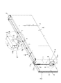
図1は、本発明の間仕切装置の一実施形態の一部を示す斜視図である。
この間仕切装置は、左右1対の支柱1、1の前後面に、複数のパネル2を上下多段状に架設したものよりなっている。図1には、前後1対のパネル2、2の上部のみを示してあるが、図5(c)には、上下のパネル2、2の対向端部の断面形状を示してある。
FIG. 1 is a perspective view showing a part of an embodiment of the partition device of the present invention.
This partitioning device is composed of a plurality of
各支柱1は、鋼管等の角管により形成されている。
各パネル2は、所要の縦横寸法に形成された方形の薄鋼板からなる化粧板3の裏面に、石膏ボード等の断熱性、遮音性に富む所要厚さの芯材4を固着したものにより形成されている。
Each column 1 is formed of a square tube such as a steel pipe.
Each
各化粧板3の左右両側縁および上縁には、裏面側にコ字状に折返すことにより、折返し部3aが形成され、支柱1に当接する両側部の折返し部3aの背面には、上下方向を向くスリット状の複数の係止孔5が、上下方向に適宜の間隔をもって穿設されており、図2に拡大して示すように、支柱1の側面にスポット溶接またはねじ止等により固着されたブラケット6の前後に突設した上向きのフック6aに、各係止孔5を係止することによって、各パネル2は、左右の支柱1、1に架設されている。
Folded portions 3a are formed on the left and right side edges and the upper edge of each
図5(c)に示すように、各化粧板3の下縁には、裏面側にクランク状に折曲することにより、下端後部に下向き突片3bを備える折曲部3cが形成されている。
この下向き突片3bを、下段のパネル2の上端における折返し部3aの背面に係合させることにより、上段のパネル2の下端部は、下段のパネル2の上端より前後方向の外側に移動するのが阻止される。
As shown in FIG.5 (c), the bending part 3c provided with the
By engaging the downward projecting
芯材4は、左右両側縁と上縁との折返し部3aと、下縁の折曲部3cとにより囲まれた化粧板3の裏面に固着されている。
The core material 4 is fixed to the back surface of the
化粧板3の上縁の折返し部3aの背面における左右方向の中間部には、左右方向に長い複数の長孔7が、左右方向に適宜の間隔をもって形成され、この長孔7には、前後に対向するパネル2、2の間隔Wを一定に保持するための間隔保持部材8が装着され、また、この間隔保持部材8上には、補助部材9が跨嵌されている。
A plurality of
間隔保持部材8は、やや厚手の金属プレス成形体から構成されるものであり、図3に拡大して示すように、パネル間隔Wより僅かに小さな幅寸法であって、上方に向かって開口する側面視上向きコ字状をなし、両パネル2、2の内方への移動を阻止するスペーサ部8aと、このスペーサ部8aの前後の端部に連設されるとともに、平面視において互いに左右の逆方向を向くフック状をなし、両パネル2、2のほぼ前後に対向する長孔7、7の互いに異なる左右の縁に係合することにより、両パネル2、2の前後方向の外向きの移動を阻止するようにした拡幅阻止部8b、8bとを備えている。
The
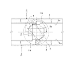
図4に実線で示すように、間隔保持部材8を前後のパネル2、2に架設したときのスペーサ部8aにおけるパネル2、2と平行な方向の長さは、両パネル2、2の間隔Wより小とし、かつパネル2、2と直交する方向のスペーサ部8aの長さは、両パネル2、2の間隔Wとほぼ同一か、または若干小としてある。
As shown by a solid line in FIG. 4, the length of the
なお、間隔保持部材8が、図4に実線で示すように、両パネル2、2と直交する前後方向を向いたとき、前後の拡幅阻止部8b、8bが、両パネル2、2の長孔7、7の左右の逆の縁に係合するように、前後のパネル2、2における対向する長孔7、7の左右方向の位置を若干ずらせておくのが好ましい。
When the
補助部材9は、間隔保持部材8と同様に、やや厚手の金属プレス成形体から構成され、図3に拡大して示すように、水平片9aの前後の端部に垂下片9b、9bを設けた側面視下向きコ字状をなし、両垂下片9b、9bの下端中央部に、間隔保持部材8におけるフック状の拡幅阻止部8b、8bの基部(またはスペーサ部8aの両側部)が嵌合するようにした切欠き10を設けたものよりなっている。
両垂下片9b、9bの下端部には、必要に応じて、補強のための内向き折曲片9c、9cを設けるのがよい。
The
It is preferable to provide inwardly
次に、間隔保持部材8および補助部材9の取付手順について、図4および図5を参照して説明する。
Next, the attachment procedure of the space |
左右1対の支柱1、1の前後面に、前後1対のパネル2、2を架設した後、前後のパネル2、2間に、間隔保持部材8を、図4に2点鎖線で示すように、その長軸がパネル2、2と同方向を向くようにして嵌合し、次いで、垂直軸線回りにほぼ90度回転させて、両拡幅阻止部8b、8bを、両パネル2、2の長孔7、7の左右の逆の縁に係合させる。
After a pair of front and
スペーサ部8aの平面視における対角線が、両パネル2、2と直交する方向を向くとき、スペーサ部8aの横幅が最大となり、これが、両パネル2、2の間隔Wより大となることがあるが、その場合は、両パネル2、2の中間部を、一時的に外向きに弾性撓曲させて、上記対角線の部分を通過させればよい。
When the diagonal line in the plan view of the
間隔保持部材8が両パネル2、2に架設されることにより、前後のパネル2、2は、最も湾曲または変形しやすい中間部の内方への移動が、間隔保持部材8のスペーサ部8aにより阻止され、また同じく、中間部の前後方向の外方への移動が、間隔保持部材8の拡幅阻止部8b、8bにより阻止されるので、両パネル2、2の湾曲や反りが防止されるとともに、支柱1、1からの脱落も防止される。
したがって、従来の間仕切装置における中間連結材や下部連結材を省略することができ、間仕切装置全体の構造を簡素化することができる。
When the spacing
Therefore, the intermediate connecting material and the lower connecting material in the conventional partition device can be omitted, and the entire structure of the partition device can be simplified.
また、間隔保持部材8を、金属板等をプレス加工するだけで、簡単かつ安価に製造することができるとともに、間隔保持部材8を、両パネル2、2間に挿入して、ほぼ90度回転させるだけで、両パネル2、2に、簡単かつ迅速に取付けることができる。
In addition, the spacing
さらに、上記と逆の操作を行うことにより、すなわち、間隔保持部材8を、上記と逆の方向に90度回転させた後、両パネル2、2間から上方に取り出すことにより、間隔保持部材8を、両パネル2、2間から、簡単に取外すことができる。
Further, by performing an operation reverse to the above, that is, by rotating the
次に、図5(a)に示すように、前後のパネル2、2間に架設された間隔保持部材8の上方より、補助部材9を、その切欠き10に間隔保持部材8におけるフック状の拡幅阻止部8b、8bの基部が嵌合するようにして跨嵌する。
Next, as shown in FIG. 5 (a), the
このとき、図5(b)に示すように、補助部材9の上部は、両パネル2、2の上端より上方に突出する。また、補助部材9における両垂下片9b、9bの下部外側面は、前後のパネル2、2の背面に当接するようにしておくのが望ましい。
At this time, as shown in FIG. 5B, the upper part of the
次に、図5(c)に示すように、前後のパネル2、2上に、上段のパネル2、2を、その下向き突片3bが下段のパネル2の上端における折返し部3aの背面に係合するとともに、各パネル2の背面が、補助部材9における両垂下片9b、9bの上部外周面に当接し、また、各パネル2の両側部の背面に設けた係止孔5の上縁が、ブラケット6のフック6aに係止されるようにして架設する。
Next, as shown in FIG. 5 (c), the
したがって、上段の各パネル2の下端部は、その背面が補助部材9における両垂下片9b、9bの上部外周面に当接していることにより、前後方向の内方への移動が阻止され、また、下向き突片3bが、下段のパネル2の上端における折返し部3aの背面に係合していることにより、下段のパネル2の上端より前後方向の外側への移動が阻止され、上下のパネル2、2の突き合わせ部分に段差が生じるのを防止することができる。
Therefore, the lower end portion of each
本発明は、上記実施形態のみに限定されるものではなく、特許請求の範囲を逸脱することなく、例えば、次のような幾多の変形した態様での実施が可能である。 The present invention is not limited only to the above-described embodiments, and can be implemented in various modified modes as follows, for example, without departing from the scope of the claims.
(a) 図1においては、間隔保持部材8と補助部材9とをそれぞれ1個ずつ示してあるが、支柱1、1の前後面に、1対のパネル2、2のみを装着する場合や、最上段のパネル2、2の上端部に装着する場合は、補助部材9を省略して、間隔保持部材8のみを装着する。
また、間隔保持部材8と補助部材9とは、状況に応じて、図1に示す前後のパネル2、2に設けられた3個の長孔7のうち、中央の1個のみに装着したり、両側の2個に装着したり、または3個全部に装着したりすることができる。
(a) In FIG. 1, one
Further, depending on the situation, the spacing
(b) 図示の例では、間隔保持部材8のスペーサ部8aを、上方に開口する側面視上向コ字状としてあるが、これを、下方に開口する側面視下向きコ字状とする。この場合、そのスペーサ部8aの上部を、下段のパネル2、2の上方に突出させて、上段のパネル2、2間に嵌合し、上段のパネル2、2の内方への移動を阻止するスペーサとしても兼用することができる。
(b) In the example shown in the figure, the
1 支柱
2 パネル
3 化粧板
3a折返し部
3b下向き突片
3c折曲部
4 芯材
5 係止孔
6 ブラケット
6aフック
7 長孔
8 間隔保持部材
8aスペーサ部
8b拡幅阻止部
9 補助部材
9a水平片
9b垂下片
9c内向き折曲片
10切欠き
W 間隔
DESCRIPTION OF SYMBOLS 1 Support |
Claims (7)
前後のパネルの左右方向の適所に、両パネルの内方への移動を阻止するスペーサ部と、両パネルの外方への移動を阻止する拡幅阻止部とを備える間隔保持部材を架設したことを特徴とする間仕切装置。 In the partition device in which panels are installed before and after the left and right columns,
A spacing member comprising a spacer portion for preventing the inward movement of both panels and a widening prevention portion for preventing the outward movement of both panels at appropriate positions in the left and right direction of the front and rear panels. A partition device characterized.
Priority Applications (1)
| Application Number | Priority Date | Filing Date | Title |
|---|---|---|---|
| JP2007167520A JP5117124B2 (en) | 2007-06-26 | 2007-06-26 | Partition device |
Applications Claiming Priority (1)
| Application Number | Priority Date | Filing Date | Title |
|---|---|---|---|
| JP2007167520A JP5117124B2 (en) | 2007-06-26 | 2007-06-26 | Partition device |
Publications (2)
| Publication Number | Publication Date |
|---|---|
| JP2009007748A true JP2009007748A (en) | 2009-01-15 |
| JP5117124B2 JP5117124B2 (en) | 2013-01-09 |
Family
ID=40323102
Family Applications (1)
| Application Number | Title | Priority Date | Filing Date |
|---|---|---|---|
| JP2007167520A Expired - Fee Related JP5117124B2 (en) | 2007-06-26 | 2007-06-26 | Partition device |
Country Status (1)
| Country | Link |
|---|---|
| JP (1) | JP5117124B2 (en) |
Cited By (1)
| Publication number | Priority date | Publication date | Assignee | Title |
|---|---|---|---|---|
| JP2023079350A (en) * | 2021-11-29 | 2023-06-08 | 三和シヤッター工業株式会社 | Upward movement control structure in the panel body |
Families Citing this family (1)
| Publication number | Priority date | Publication date | Assignee | Title |
|---|---|---|---|---|
| JP6220230B2 (en) * | 2013-11-01 | 2017-10-25 | 株式会社岡村製作所 | Panel connection structure |
Citations (1)
| Publication number | Priority date | Publication date | Assignee | Title |
|---|---|---|---|---|
| JP2000282607A (en) * | 1999-03-29 | 2000-10-10 | Kokuyo Co Ltd | Horizontal joint panel mounting structure |
-
2007
- 2007-06-26 JP JP2007167520A patent/JP5117124B2/en not_active Expired - Fee Related
Patent Citations (1)
| Publication number | Priority date | Publication date | Assignee | Title |
|---|---|---|---|---|
| JP2000282607A (en) * | 1999-03-29 | 2000-10-10 | Kokuyo Co Ltd | Horizontal joint panel mounting structure |
Cited By (2)
| Publication number | Priority date | Publication date | Assignee | Title |
|---|---|---|---|---|
| JP2023079350A (en) * | 2021-11-29 | 2023-06-08 | 三和シヤッター工業株式会社 | Upward movement control structure in the panel body |
| JP7812649B2 (en) | 2021-11-29 | 2026-02-10 | 三和シヤッター工業株式会社 | Panel body upward movement restriction structure |
Also Published As
| Publication number | Publication date |
|---|---|
| JP5117124B2 (en) | 2013-01-09 |
Similar Documents
| Publication | Publication Date | Title |
|---|---|---|
| JP2013224574A (en) | Ceiling substrate structure | |
| RU2010121719A (en) | CONVENIENT WIDE WALL CORNER | |
| JP5117124B2 (en) | Partition device | |
| KR101389958B1 (en) | Celling louver | |
| JP5282327B2 (en) | Interlayer refractory support bracket | |
| JP6358830B2 (en) | Ceiling foundation structure | |
| US20070107353A1 (en) | Cross panel | |
| JP4518434B2 (en) | Assembly shelf | |
| JP5261547B2 (en) | Product display shelf | |
| JP6261346B2 (en) | Panel mounting structure | |
| JP2012047010A (en) | Expansion joint structure | |
| JP2020026726A (en) | Baseboard and installation structure of baseboard | |
| JP5266115B2 (en) | Outer wall material mounting bracket and outer wall material mounting structure | |
| JP6047034B2 (en) | Field edge and ceiling structure using it | |
| JP6152979B2 (en) | Ceiling material falling prevention mechanism and suspended ceiling structure provided with the same | |
| JP7249628B2 (en) | Support device | |
| JP7457514B2 (en) | partition wall device | |
| JP2017036629A (en) | Fixing structure of blind panel and fixing method for the same | |
| JP2008055032A (en) | Simple kit-shelf | |
| JP6302689B2 (en) | Ceiling foundation structure | |
| JP2000189258A (en) | Storage shelf seismic isolation device | |
| JP6302699B2 (en) | Ceiling foundation structure | |
| JP4568136B2 (en) | Building roof tile support bracket. | |
| JP2010196333A (en) | Hanging frame for bathroom | |
| JP2006037490A (en) | Refractory plate mounting structure to steel segment |
Legal Events
| Date | Code | Title | Description |
|---|---|---|---|
| A621 | Written request for application examination |
Free format text: JAPANESE INTERMEDIATE CODE: A621 Effective date: 20100617 |
|
| A977 | Report on retrieval |
Free format text: JAPANESE INTERMEDIATE CODE: A971007 Effective date: 20120208 |
|
| A131 | Notification of reasons for refusal |
Free format text: JAPANESE INTERMEDIATE CODE: A131 Effective date: 20120221 |
|
| A521 | Written amendment |
Free format text: JAPANESE INTERMEDIATE CODE: A523 Effective date: 20120416 |
|
| TRDD | Decision of grant or rejection written | ||
| A01 | Written decision to grant a patent or to grant a registration (utility model) |
Free format text: JAPANESE INTERMEDIATE CODE: A01 Effective date: 20120918 |
|
| A01 | Written decision to grant a patent or to grant a registration (utility model) |
Free format text: JAPANESE INTERMEDIATE CODE: A01 |
|
| A61 | First payment of annual fees (during grant procedure) |
Free format text: JAPANESE INTERMEDIATE CODE: A61 Effective date: 20121017 |
|
| R150 | Certificate of patent or registration of utility model |
Free format text: JAPANESE INTERMEDIATE CODE: R150 Ref document number: 5117124 Country of ref document: JP Free format text: JAPANESE INTERMEDIATE CODE: R150 |
|
| FPAY | Renewal fee payment (event date is renewal date of database) |
Free format text: PAYMENT UNTIL: 20151026 Year of fee payment: 3 |
|
| R250 | Receipt of annual fees |
Free format text: JAPANESE INTERMEDIATE CODE: R250 |
|
| R250 | Receipt of annual fees |
Free format text: JAPANESE INTERMEDIATE CODE: R250 |
|
| R250 | Receipt of annual fees |
Free format text: JAPANESE INTERMEDIATE CODE: R250 |
|
| R250 | Receipt of annual fees |
Free format text: JAPANESE INTERMEDIATE CODE: R250 |
|
| S533 | Written request for registration of change of name |
Free format text: JAPANESE INTERMEDIATE CODE: R313533 |
|
| R350 | Written notification of registration of transfer |
Free format text: JAPANESE INTERMEDIATE CODE: R350 |
|
| LAPS | Cancellation because of no payment of annual fees |