JP2009007748A - 間仕切装置 - Google Patents
間仕切装置 Download PDFInfo
- Publication number
- JP2009007748A JP2009007748A JP2007167520A JP2007167520A JP2009007748A JP 2009007748 A JP2009007748 A JP 2009007748A JP 2007167520 A JP2007167520 A JP 2007167520A JP 2007167520 A JP2007167520 A JP 2007167520A JP 2009007748 A JP2009007748 A JP 2009007748A
- Authority
- JP
- Japan
- Prior art keywords
- panels
- partition device
- panel
- spacer portion
- spacing member
- Prior art date
- Legal status (The legal status is an assumption and is not a legal conclusion. Google has not performed a legal analysis and makes no representation as to the accuracy of the status listed.)
- Granted
Links
- 238000005192 partition Methods 0.000 title claims abstract description 22
- 125000006850 spacer group Chemical group 0.000 claims abstract description 29
- 230000000903 blocking effect Effects 0.000 claims description 7
- 230000002265 prevention Effects 0.000 claims description 6
- 238000000638 solvent extraction Methods 0.000 claims description 4
- 230000002401 inhibitory effect Effects 0.000 abstract 3
- 238000006073 displacement reaction Methods 0.000 abstract 2
- 239000000463 material Substances 0.000 description 7
- 238000005452 bending Methods 0.000 description 6
- 239000002184 metal Substances 0.000 description 6
- 239000011162 core material Substances 0.000 description 3
- 229910000831 Steel Inorganic materials 0.000 description 2
- 238000009413 insulation Methods 0.000 description 2
- 230000002093 peripheral effect Effects 0.000 description 2
- 239000010959 steel Substances 0.000 description 2
- 230000000694 effects Effects 0.000 description 1
- 238000000034 method Methods 0.000 description 1
- 239000011505 plaster Substances 0.000 description 1
- 230000002787 reinforcement Effects 0.000 description 1
- 238000003466 welding Methods 0.000 description 1
Images



Landscapes
- Panels For Use In Building Construction (AREA)
- Fencing (AREA)
Abstract
【解決手段】左右の支柱1の前後に、パネル2を架設した間仕切装置において、前後のパネル2の左右方向の中間部に、両パネル2の内方への移動を阻止するスペーサ部8aと、両パネル2の外方への移動を阻止する拡幅阻止部8bとを備える間隔保持部材8を架設する。
【選択図】 図1
Description
(1)左右の支柱の前後に、パネルを架設した間仕切装置において、前後のパネルの左右方向の適所に、両パネルの内方への移動を阻止するスペーサ部と、両パネルの外方への移動を阻止する拡幅阻止部とを備える間隔保持部材を架設する。
請求項1記載の発明によると、最も湾曲または変形しやすいパネルの適所、例えば中間部に、間隔保持部材を取付けるだけで、両パネルの中間部の内方への移動が、間隔保持部材のスペーサ部により阻止され、また同じく、中間部の外方への移動が、間隔保持部材の拡幅阻止部により阻止されるので、両パネルの湾曲や反りを防止することができるとともに、両パネルの支柱からの脱落を防止することができる。
したがって、従来の間仕切装置における中間連結材や下部連結材を省略することができ、間仕切装置全体の構造を簡素化することができる。
また、補助部材の両垂下片が、下段の前後のパネルの背面と、上段の前後のパネルの背面とに当接するようにしてあるので、上下のパネルの突き合わせ部分に段差が生じるのを防止することができる。
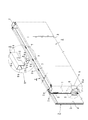
この間仕切装置は、左右1対の支柱1、1の前後面に、複数のパネル2を上下多段状に架設したものよりなっている。図1には、前後1対のパネル2、2の上部のみを示してあるが、図5(c)には、上下のパネル2、2の対向端部の断面形状を示してある。
各パネル2は、所要の縦横寸法に形成された方形の薄鋼板からなる化粧板3の裏面に、石膏ボード等の断熱性、遮音性に富む所要厚さの芯材4を固着したものにより形成されている。
この下向き突片3bを、下段のパネル2の上端における折返し部3aの背面に係合させることにより、上段のパネル2の下端部は、下段のパネル2の上端より前後方向の外側に移動するのが阻止される。
両垂下片9b、9bの下端部には、必要に応じて、補強のための内向き折曲片9c、9cを設けるのがよい。
したがって、従来の間仕切装置における中間連結材や下部連結材を省略することができ、間仕切装置全体の構造を簡素化することができる。
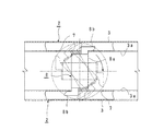
また、間隔保持部材8と補助部材9とは、状況に応じて、図1に示す前後のパネル2、2に設けられた3個の長孔7のうち、中央の1個のみに装着したり、両側の2個に装着したり、または3個全部に装着したりすることができる。
2 パネル
3 化粧板
3a折返し部
3b下向き突片
3c折曲部
4 芯材
5 係止孔
6 ブラケット
6aフック
7 長孔
8 間隔保持部材
8aスペーサ部
8b拡幅阻止部
9 補助部材
9a水平片
9b垂下片
9c内向き折曲片
10切欠き
W 間隔
Claims (7)
- 左右の支柱の前後に、パネルを架設した間仕切装置において、
前後のパネルの左右方向の適所に、両パネルの内方への移動を阻止するスペーサ部と、両パネルの外方への移動を阻止する拡幅阻止部とを備える間隔保持部材を架設したことを特徴とする間仕切装置。 - スペーサ部を、上方または下方に開口する側面視上向きまたは下向きコ字状とした請求項1記載の間仕切装置。
- 拡幅阻止部を、スペーサ部の前後の端部に連設され、かつ両パネルの前後の対向面に設けた左右方向に長い長孔の互いに異なる左右の縁に係合するようにした、左右の互いに異なる方向を向くフックとした請求項1または2記載の間仕切装置。
- 間隔保持部材を両パネルに架設したときのスペーサ部におけるパネルと平行な方向の長さを、両パネルの間隔より小とし、かつ前記パネルと直交する方向のスペーサ部の長さを、両パネルの間隔とほぼ同一とすることにより、前記間隔保持部材を、長手方向をパネルと同方向に向けて、両パネル間に嵌合し、次いで、垂直軸線回りにほぼ90度回転させて、両フックを両パネルの長孔の左右の縁に係合可能としたことを特徴とする請求項3記載の間仕切装置。
- 左右の支柱の前後に、複数のパネルを上下多段状に架設し、下段の前後のパネルの上部における左右方向の適所間に、間隔保持部材を架設し、かつ前記間隔保持部材におけるスペーサ部に、下段の前後のパネルより上方に突出する上部が、下段の前後のパネルの上方に配設した上段の前後のパネル間に嵌合するようにした補助部材を跨嵌したことを特徴とする請求項1〜4のいずれかに記載の間仕切装置。
- 補助部材を、水平片の前後の端部に垂下片を設けた側面視下向きコ字状とし、かつ前記両垂下片の下端中央部に、間隔保持部材が嵌合するようにした切欠きを設け、両垂下片が、下段の前後のパネルの背面と、上段の前後のパネルの背面とに当接するようにしたことを特徴とする請求項5記載の間仕切装置。
- 上段の前後のパネルの下端に、下段の前後のパネルの上端部背面に係合する下向き突片を設けたことを特徴とする請求項5または6記載の間仕切装置。
Priority Applications (1)
| Application Number | Priority Date | Filing Date | Title |
|---|---|---|---|
| JP2007167520A JP5117124B2 (ja) | 2007-06-26 | 2007-06-26 | 間仕切装置 |
Applications Claiming Priority (1)
| Application Number | Priority Date | Filing Date | Title |
|---|---|---|---|
| JP2007167520A JP5117124B2 (ja) | 2007-06-26 | 2007-06-26 | 間仕切装置 |
Publications (2)
| Publication Number | Publication Date |
|---|---|
| JP2009007748A true JP2009007748A (ja) | 2009-01-15 |
| JP5117124B2 JP5117124B2 (ja) | 2013-01-09 |
Family
ID=40323102
Family Applications (1)
| Application Number | Title | Priority Date | Filing Date |
|---|---|---|---|
| JP2007167520A Expired - Fee Related JP5117124B2 (ja) | 2007-06-26 | 2007-06-26 | 間仕切装置 |
Country Status (1)
| Country | Link |
|---|---|
| JP (1) | JP5117124B2 (ja) |
Cited By (1)
| Publication number | Priority date | Publication date | Assignee | Title |
|---|---|---|---|---|
| JP2023079350A (ja) * | 2021-11-29 | 2023-06-08 | 三和シヤッター工業株式会社 | パネル体における上動規制構造 |
Families Citing this family (1)
| Publication number | Priority date | Publication date | Assignee | Title |
|---|---|---|---|---|
| JP6220230B2 (ja) * | 2013-11-01 | 2017-10-25 | 株式会社岡村製作所 | パネルの接続構造 |
Citations (1)
| Publication number | Priority date | Publication date | Assignee | Title |
|---|---|---|---|---|
| JP2000282607A (ja) * | 1999-03-29 | 2000-10-10 | Kokuyo Co Ltd | 横目地パネル取付構造 |
-
2007
- 2007-06-26 JP JP2007167520A patent/JP5117124B2/ja not_active Expired - Fee Related
Patent Citations (1)
| Publication number | Priority date | Publication date | Assignee | Title |
|---|---|---|---|---|
| JP2000282607A (ja) * | 1999-03-29 | 2000-10-10 | Kokuyo Co Ltd | 横目地パネル取付構造 |
Cited By (2)
| Publication number | Priority date | Publication date | Assignee | Title |
|---|---|---|---|---|
| JP2023079350A (ja) * | 2021-11-29 | 2023-06-08 | 三和シヤッター工業株式会社 | パネル体における上動規制構造 |
| JP7812649B2 (ja) | 2021-11-29 | 2026-02-10 | 三和シヤッター工業株式会社 | パネル体における上動規制構造 |
Also Published As
| Publication number | Publication date |
|---|---|
| JP5117124B2 (ja) | 2013-01-09 |
Similar Documents
| Publication | Publication Date | Title |
|---|---|---|
| JP2013224574A (ja) | 天井下地構造 | |
| RU2010121719A (ru) | Удобный широкий пристенный уголок | |
| JP5117124B2 (ja) | 間仕切装置 | |
| KR101389958B1 (ko) | 천장 루버 | |
| JP5282327B2 (ja) | 層間耐火材支持金具 | |
| JP6358830B2 (ja) | 天井下地構造 | |
| US20070107353A1 (en) | Cross panel | |
| JP4518434B2 (ja) | 組立棚 | |
| JP5261547B2 (ja) | 商品陳列棚 | |
| JP6261346B2 (ja) | パネルの取付け構造 | |
| JP2012047010A (ja) | エキスパンションジョイント構造 | |
| JP2020026726A (ja) | 幅木及び幅木の設置構造 | |
| JP5266115B2 (ja) | 外壁材取付金具及び外壁材取付構造 | |
| JP6047034B2 (ja) | 野縁及びそれを用いた天井構造 | |
| JP6152979B2 (ja) | 天井材脱落防止機構及びこれを備えた吊り天井構造 | |
| JP7249628B2 (ja) | 支持装置 | |
| JP7457514B2 (ja) | 間仕切壁装置 | |
| JP2017036629A (ja) | 目隠しパネルの固定構造及び目隠しパネルの固定方法 | |
| JP2008055032A (ja) | 簡易組立棚 | |
| JP6302689B2 (ja) | 天井下地構造 | |
| JP2000189258A (ja) | 収納棚の防震装置 | |
| JP6302699B2 (ja) | 天井下地構造 | |
| JP4568136B2 (ja) | 棟瓦梁支持金具。 | |
| JP2010196333A (ja) | 浴室用吊り架台 | |
| JP2006037490A (ja) | スチールセグメントへの耐火板取付構造 |
Legal Events
| Date | Code | Title | Description |
|---|---|---|---|
| A621 | Written request for application examination |
Free format text: JAPANESE INTERMEDIATE CODE: A621 Effective date: 20100617 |
|
| A977 | Report on retrieval |
Free format text: JAPANESE INTERMEDIATE CODE: A971007 Effective date: 20120208 |
|
| A131 | Notification of reasons for refusal |
Free format text: JAPANESE INTERMEDIATE CODE: A131 Effective date: 20120221 |
|
| A521 | Written amendment |
Free format text: JAPANESE INTERMEDIATE CODE: A523 Effective date: 20120416 |
|
| TRDD | Decision of grant or rejection written | ||
| A01 | Written decision to grant a patent or to grant a registration (utility model) |
Free format text: JAPANESE INTERMEDIATE CODE: A01 Effective date: 20120918 |
|
| A01 | Written decision to grant a patent or to grant a registration (utility model) |
Free format text: JAPANESE INTERMEDIATE CODE: A01 |
|
| A61 | First payment of annual fees (during grant procedure) |
Free format text: JAPANESE INTERMEDIATE CODE: A61 Effective date: 20121017 |
|
| R150 | Certificate of patent or registration of utility model |
Free format text: JAPANESE INTERMEDIATE CODE: R150 Ref document number: 5117124 Country of ref document: JP Free format text: JAPANESE INTERMEDIATE CODE: R150 |
|
| FPAY | Renewal fee payment (event date is renewal date of database) |
Free format text: PAYMENT UNTIL: 20151026 Year of fee payment: 3 |
|
| R250 | Receipt of annual fees |
Free format text: JAPANESE INTERMEDIATE CODE: R250 |
|
| R250 | Receipt of annual fees |
Free format text: JAPANESE INTERMEDIATE CODE: R250 |
|
| R250 | Receipt of annual fees |
Free format text: JAPANESE INTERMEDIATE CODE: R250 |
|
| R250 | Receipt of annual fees |
Free format text: JAPANESE INTERMEDIATE CODE: R250 |
|
| S533 | Written request for registration of change of name |
Free format text: JAPANESE INTERMEDIATE CODE: R313533 |
|
| R350 | Written notification of registration of transfer |
Free format text: JAPANESE INTERMEDIATE CODE: R350 |
|
| LAPS | Cancellation because of no payment of annual fees |