JP2009007771A - Door switch system - Google Patents
Door switch system Download PDFInfo
- Publication number
- JP2009007771A JP2009007771A JP2007168059A JP2007168059A JP2009007771A JP 2009007771 A JP2009007771 A JP 2009007771A JP 2007168059 A JP2007168059 A JP 2007168059A JP 2007168059 A JP2007168059 A JP 2007168059A JP 2009007771 A JP2009007771 A JP 2009007771A
- Authority
- JP
- Japan
- Prior art keywords
- door
- switch system
- door switch
- magnet
- magnetic sensor
- Prior art date
- Legal status (The legal status is an assumption and is not a legal conclusion. Google has not performed a legal analysis and makes no representation as to the accuracy of the status listed.)
- Granted
Links
- 230000005672 electromagnetic field Effects 0.000 claims description 8
- 229910052751 metal Inorganic materials 0.000 description 23
- 239000002184 metal Substances 0.000 description 23
- 238000010586 diagram Methods 0.000 description 12
- 238000012986 modification Methods 0.000 description 7
- 230000004048 modification Effects 0.000 description 7
- 238000013461 design Methods 0.000 description 4
- 235000014676 Phragmites communis Nutrition 0.000 description 3
- 238000003825 pressing Methods 0.000 description 3
- 230000001681 protective effect Effects 0.000 description 3
- XEEYBQQBJWHFJM-UHFFFAOYSA-N Iron Chemical compound [Fe] XEEYBQQBJWHFJM-UHFFFAOYSA-N 0.000 description 2
- 229910000828 alnico Inorganic materials 0.000 description 2
- 238000013459 approach Methods 0.000 description 2
- 238000007796 conventional method Methods 0.000 description 2
- 238000001514 detection method Methods 0.000 description 2
- 230000000694 effects Effects 0.000 description 2
- 239000000696 magnetic material Substances 0.000 description 2
- 229910052761 rare earth metal Inorganic materials 0.000 description 2
- 150000002910 rare earth metals Chemical class 0.000 description 2
- 229910000859 α-Fe Inorganic materials 0.000 description 2
- 238000005516 engineering process Methods 0.000 description 1
- 230000001747 exhibiting effect Effects 0.000 description 1
- 229910052742 iron Inorganic materials 0.000 description 1
- 239000000463 material Substances 0.000 description 1
- 238000000034 method Methods 0.000 description 1
- 230000035699 permeability Effects 0.000 description 1
Images



Landscapes
- Lock And Its Accessories (AREA)
Abstract
Description
本発明は、ドアシステムの施錠状態を検出するドアスイッチシステムに関し、特に、小型で耐久性が高くかつ無効化が困難なドアスイッチシステムを実現する技術に関する。 The present invention relates to a door switch system that detects a locked state of a door system, and more particularly, to a technique that realizes a door switch system that is small, highly durable, and difficult to invalidate.
従来、ドアシステムの施錠状態を検出する様々なドアスイッチシステム、及びその応用が提案され、実用化されている。 Conventionally, various door switch systems for detecting a locked state of a door system and applications thereof have been proposed and put into practical use.
例えば、第1の従来技術として、ストライクボックス内にマイクロスイッチを設け、デッドボルトが前記マイクロスイッチを押圧することによって、室内照明をオフするキースイッチが知られている。 For example, as a first prior art, a key switch is known in which a micro switch is provided in a strike box, and a dead bolt presses the micro switch to turn off the room lighting.
このキースイッチによれば、ドアの施錠及び開錠に連動して、室内照明を自動的にオフおよびオンできるので、室内照明の消し忘れや、点灯のために暗がりでスイッチを探す不便が解消される。 According to this key switch, the interior lighting can be automatically turned off and on in conjunction with the locking and unlocking of the door, eliminating the inconvenience of forgetting to turn off the interior lighting and searching for the switch in the dark for lighting. The
また、第2の従来技術として、ドアに取り付けられる扉錠、及び枠等に取り付けられる受座の一方にリードスイッチ、他方に永久磁石を設けたスイッチング装置であって、非磁性体で製作された前記扉錠及び受座のフロント板の一部に、鉄等の透磁率の高い材料からなる中間部材を設けたスイッチング装置が知られている。 In addition, as a second prior art, a switching device provided with a reed switch on one side of a door lock attached to a door and a seat attached to a frame or the like and a permanent magnet on the other side, which is made of a non-magnetic material. There is known a switching device in which an intermediate member made of a material having high magnetic permeability such as iron is provided on a part of the door lock and the front plate of the seat.
このスイッチング装置によれば、磁力を用いて検出を行う場合に、磁力線を前記中間部材に集約することによって、磁力線を前記リードスイッチに効率よく導くことができる。 According to this switching device, when detection is performed using magnetic force, the magnetic force lines can be efficiently guided to the reed switch by concentrating the magnetic force lines on the intermediate member.
ドアスイッチシステムを、インターロックシステムに応用することも可能である。
特許文献1には、インターロックシステムを備えたピッキング装置の一例が開示されている。特許文献1に開示されるインターロックシステムは、安全柵で囲われたピッキング装置において、前記安全柵内に入り込んだ人を検知する人体センサを設け、前記人体センサが人を検知した場合に前記ピッキング装置を非常停止させる。
The door switch system can also be applied to an interlock system.
例えば、このインターロックシステムにおいて、前記安全柵の扉部の施錠状態をドアスイッチシステムにより検出し、施錠状態が検出されない場合に前記ピッキング装置を非常停止させることによって、安全性をさらに向上させることができる。 For example, in this interlock system, the locking state of the door part of the safety fence is detected by a door switch system, and when the locking state is not detected, the picking device can be emergency stopped to further improve safety. it can.
ドアスイッチシステムをインターロックシステムに用いる場合には、無効化が困難であることが求められる。ここで言う無効化とは、安全上必要なオーバヘッドを不正に省こうと企図した作業者が、ドアシステムが実際には施錠されていない状態で、ドアスイッチシステムに施錠状態を誤検出させることである。 When a door switch system is used for an interlock system, it is required that invalidation is difficult. Disabling here means that an operator who intends to illegally omit the overhead required for safety causes the door switch system to falsely detect the locked state when the door system is not actually locked. is there.
そこで、第3の従来技術として、無効化が困難となるように構成されたドアスイッチシステムが市販されている。 Therefore, as a third conventional technique, a door switch system configured to be difficult to invalidate is commercially available.
図6は、そのようなドアスイッチシステムの一典型例を示す構成図である。
図6に示されるドアスイッチシステムは、ドア及びドア枠の一方及び他方にそれぞれ面付けされる錠本体部91と受け金具92とから構成され、施錠の際、所定形状のスライドキー93が、スライドキー93の破損を防ぐための保護金具94と共に錠本体部91から突出し、受け金具92内へ進入する。そして、スライドキー93が受け金具92内に設けられたセンサスイッチ95と嵌合することにより施錠状態を検出する。
FIG. 6 is a block diagram showing a typical example of such a door switch system.
The door switch system shown in FIG. 6 is composed of a lock
このドアスイッチシステムによれば、所定形状のスライドキー93とセンサスイッチ95とが嵌合しない限り施錠状態が検出されないので、ありあわせの部材を受け金具92に差し込むなどしても容易には無効化できない。
しかしながら、従来の技術によれば、小型で耐久性が高くかつ無効化が困難なドアスイッチシステムを実現することが難しいという問題がある。 However, according to the conventional technology, there is a problem that it is difficult to realize a door switch system that is small, highly durable, and difficult to disable.
第1の従来技術のキースイッチは、彫込み錠に埋設される程度に小型に実現可能であるが、マイクロスイッチをありあわせの部材で押圧するだけで容易に無効化できてしまう。また、機械的なマイクロスイッチを用いるため耐久性の点で劣る。 The key switch of the first prior art can be realized so small as to be embedded in the engraved lock, but can be easily invalidated simply by pressing the microswitch with a common member. Moreover, since a mechanical microswitch is used, it is inferior in durability.
第2の従来技術のスイッチング装置は、永久磁石とリードスイッチとを用いて施錠状態を検出することから、良好な耐久性を有しかつ無効化が比較的困難であると考えられるが、フロント板に中間部材を設けるためのスペースが必要となるため小型化の点で不利である。 Since the second prior art switching device detects the locked state using a permanent magnet and a reed switch, it is considered that it has good durability and is relatively difficult to invalidate. This requires a space for providing an intermediate member, which is disadvantageous in terms of miniaturization.
第3の従来技術のドアスイッチシステムによれば、無効化は困難であるが、スライドキーを保護する比較的大きな保護金具を備えるため小型化の点で不利である。また、ドアスイッチシステムが面付けにより露出した状態で設置されることは、デザインが制限されることや、保安の面から必ずしも好ましいとは言えない。 According to the third conventional door switch system, it is difficult to invalidate, but it is disadvantageous in terms of miniaturization because it includes a relatively large protective metal fitting for protecting the slide key. In addition, it is not necessarily preferable that the door switch system is installed in an exposed state due to imposition because the design is limited or from the viewpoint of security.
本発明は、このような事情に鑑みてなされたものであり、小型で耐久性が高くかつ無効化が困難なドアスイッチシステムを提供することを目的とする。 The present invention has been made in view of such circumstances, and an object thereof is to provide a door switch system that is small in size, high in durability, and difficult to invalidate.
上記問題を解決するため、本発明のドアスイッチシステムは、ドアに出没自在に取り付けられる可動部材がドア枠内へ進入することによって施錠されるドアシステムの施錠状態を検出するドアスイッチシステムであって、前記可動部材及び前記ドア枠内のうちの一方に、周囲の電磁場を変化させる被検出体を備え、他方に、前記可動部材が前記ドア枠内へ進入している場合に期待される電磁場を前記被検出体に接触することなく検出する検出器を備える。 In order to solve the above problem, the door switch system of the present invention is a door switch system that detects a locked state of a door system that is locked when a movable member that is removably attached to the door enters the door frame. One of the movable member and the door frame is provided with a detected object that changes the surrounding electromagnetic field, and the other is an electromagnetic field that is expected when the movable member enters the door frame. A detector for detecting without contacting the detected object is provided.
この構成によれば、被検出体及び検出器の一方を、例えばデッドボルトといった施錠機能を発揮するための可動部材に設けることにより、鍵本体部又は受け金具のフロント面の一部が被検出体又は検出器によって占有されることがないので、ドアスイッチシステムの小型化に役立つ。また、被検出体及び検出器の他方をドア枠内に設けることにより、彫込み錠に適用できるので、従来の面付けによるデザイン上及び保安上の不利が解消される。 According to this configuration, one of the detected body and the detector is provided on a movable member for exhibiting a locking function such as a dead bolt, so that a part of the front surface of the key body or the receiving metal is detected. Or it is not occupied by the detector, which helps to miniaturize the door switch system. In addition, since the other of the detected object and the detector is provided in the door frame, it can be applied to the engraved lock, thereby eliminating the design and security disadvantages of conventional imposition.
さらに、期待される所定の電磁場を検出することにより施錠状態を検出するので、ありあわせの部材を検出器に接近させるなどしても施錠状態は検出されず、無効化は困難である。そして、非接触で施錠状態を検出するので、耐久性も高い。 Furthermore, since the locked state is detected by detecting the expected predetermined electromagnetic field, the locked state is not detected even if a common member is brought close to the detector, and invalidation is difficult. And since a locked state is detected by non-contact, durability is also high.
また、前記被検出体は無線タグであり、前記検出器は無線タグリーダであるとしてもよい。 The detected object may be a wireless tag, and the detector may be a wireless tag reader.
この構成によれば、所定の無線タグの特性に応じて生じる電磁場の変化が検出されない限り、施錠状態が検出されない。望ましくは、前記無線タグを無線IDタグとすれば、所定のIDが読み取られない限り、施錠状態が検出されないので、無効化を極めて堅固に防止することができる。 According to this configuration, the locked state is not detected unless a change in the electromagnetic field generated according to the characteristics of the predetermined wireless tag is detected. Desirably, if the wireless tag is a wireless ID tag, the locked state is not detected unless a predetermined ID is read, so that invalidation can be prevented extremely firmly.
また、前記被検出体は磁石であり、前記検出器は磁気センサであるとしてもよい。また、望ましくは、前記磁石は、所定の磁極性順序で複数の磁石片を配列してなる磁石アレイであり、前記磁気センサは、個々に磁場方向を検出可能な複数の磁気センサを配列してなる磁気センサアレイであるとしてもよい。 The detected object may be a magnet, and the detector may be a magnetic sensor. Preferably, the magnet is a magnet array in which a plurality of magnet pieces are arranged in a predetermined magnetic polarity order, and the magnetic sensor has a plurality of magnetic sensors that can individually detect a magnetic field direction. It may be a magnetic sensor array.
この構成によれば、例えば、従来は可能だったマイクロスイッチに対する機械的な押圧による無効化が不可能となるので、無効化の防止に一定の効果が得られる。特に、磁石アレイの磁極配列を検出する構成によれば、単極の磁石を近づけただけでは施錠状態は検出されず、より確実に無効化を防止できる。 According to this configuration, for example, it becomes impossible to invalidate the micro switch by mechanical pressing, which has been possible in the past, so that a certain effect can be obtained in preventing the invalidation. In particular, according to the configuration for detecting the magnetic pole arrangement of the magnet array, the locked state is not detected only by bringing a single-pole magnet closer, and invalidation can be prevented more reliably.
本発明は、このようなドアスイッチシステムとして実現できるだけでなく、このようなドアスイッチシステムを用いたインターロックシステムとして実現することもできる。さらには、このようなインターロックシステムによる非常停止機能を備える自動倉庫や工作機械として実現することも可能である。 The present invention can be realized not only as such a door switch system but also as an interlock system using such a door switch system. Furthermore, it can be realized as an automatic warehouse or machine tool having an emergency stop function by such an interlock system.
前記説明したように、本発明のドアスイッチシステムによれば、被検出体及び検出器の一方を、前記可動部材に設けることにより、鍵本体部又は受け金具のフロント面の一部が被検出体又は検出器によって占有されることがないので、ドアスイッチシステムの小型化に役立つ。また、被検出体及び検出器の他方をドア枠内に設けることにより、彫込み錠に適用できるので、従来の面付けによるデザイン上及び保安上の不利が解消される。 As described above, according to the door switch system of the present invention, by providing one of the detected body and the detector on the movable member, a part of the front surface of the key body portion or the receiving bracket is detected body. Or it is not occupied by the detector, which helps to miniaturize the door switch system. In addition, since the other of the detected object and the detector is provided in the door frame, it can be applied to the engraved lock, thereby eliminating the design and security disadvantages of conventional imposition.
さらに、期待される所定の電磁場により施錠状態を検出するので、ありあわせの部材を検出器に接近させるなどしても施錠状態は検出されず、従って無効化は困難である。そして、非接触で施錠状態を検出するので、耐久性も高い。 Further, since the locked state is detected by a predetermined expected electromagnetic field, the locked state is not detected even if a common member is brought close to the detector, and therefore invalidation is difficult. And since a locked state is detected by non-contact, durability is also high.
本発明の実施の形態におけるドアスイッチシステムについて、図面を参照しながら詳細に説明する。 A door switch system according to an embodiment of the present invention will be described in detail with reference to the drawings.
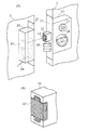
図1(A)は、実施の形態におけるドアスイッチシステムの一例を、ドアスイッチシステムが適用される開き戸システムと共に示す構成図である。 FIG. 1A is a configuration diagram illustrating an example of a door switch system according to an embodiment, together with a hinged door system to which the door switch system is applied.
この開き戸システムは、ドア1とドア枠2とからなり、ドア1に埋設される鍵本体部10、及びドア枠2に埋設される受け金具20を用いて施錠することができる。
This hinged door system includes a
鍵本体部10には、キーシリンダ11に挿入されたキーに加えられる回動力によって鍵本体部10のフロント面17から出没するデッドボルト12と、フロント面17から進出する方向に付勢され、折り畳みノブ18に加えられる回動力により鍵本体部10内へ引き込まれるラッチボルト19とが設けられる。
The
ここで、デッドボルト12が、特許請求の範囲に記載の可動部材の一例である。さらにラッチボルト19を可動部材に含めても構わない。
Here, the
受け金具20のフロント面27には、デッドボルト12及びラッチボルト19を受け入れる孔が設けられる。デッドボルト12及びラッチボルト19が、その孔から受け金具20内へ進入し、受け金具20と係合することによって、それぞれ施錠及び仮締まりが行われる。
A hole for receiving the
施錠を行うためのこのような構成は周知であるため、これ以上詳細な説明を省略する。
次に、実施の形態におけるドアスイッチシステムに特徴的な、施錠状態を検出するための構成について説明する。
Since such a structure for locking is well known, further detailed description is omitted.
Next, a configuration for detecting the locked state, which is characteristic of the door switch system in the embodiment, will be described.
このドアスイッチシステムは、デッドボルト12に取り付けられる磁石13と、受け金具20に取り付けられる磁気センサ21とを備える。ここで、磁石13が、特許請求の範囲に記載の被検出体の一例であり、磁気センサ21が特許請求の範囲に記載の検出器の一例である。
This door switch system includes a
磁石13は、例えばアルニコ磁石、フェライト磁石、希土類磁石等の周知の永久磁石である。また、磁気センサ21は、例えばホール素子、磁気抵抗素子等の周知の素子を用いて磁界強度を電気信号に変換するセンサである。
The
図1(B)は、磁石13のデッドボルト12への取り付け状態の一例を説明する拡大図である。図に見られるように、磁石13は、デッドボルト12の先端に設けられる切り欠き部に嵌め込まれ、ねじ止めされるとしてもよい。
FIG. 1B is an enlarged view for explaining an example of a state in which the
磁石13をデッドボルト12のこのような位置に取り付けることは、施錠状態においても、またドア1を開いた状態で誤って進出させたデッドボルト12を受け金具20に突き当てた場合でも、磁石13が受け金具20と直接接触しないため、耐久性に優れたドアスイッチシステムを実現する上で有利である。
The attachment of the
磁石13は、デッドボルト12の動きに伴って、図1(A)に示される鎖線に沿って、磁気センサ21に接近し、また後退する。
As the
磁気センサ21は、デッドボルト12が受け金具20内(つまり、ドア枠2内)へ進入している場合と退出している場合とで、磁石13の位置の違いから期待されるそれぞれの磁場を検出する。
The
そして、デッドボルト12が受け金具20内へ進入している場合に期待される磁場を検出すると、施錠状態を示す施錠信号を信号線29へ出力する。また、そのような磁場が検出されない場合には、デッドボルト12が受け金具20から退出しているとして、施錠信号の出力を停止する。
Then, when a magnetic field expected when the
以上説明した構成によれば、フロント面17及びフロント面27の一部が磁石13及び磁気センサ21によって占有されることがないので、ドアスイッチシステムの小型化に役立つ。また、磁気センサ21を受け金具20内に設けることにより、彫込み錠に適用できるので、従来の面付けによるデザイン上及び保安上の不利が解消される。
According to the configuration described above, the
さらに、施錠状態を磁気的に検出するので、従来の技術の1つでは可能だったマイクロスイッチに対する機械的な押圧による無効化が不可能となり、無効化の防止に一定の効果が得られる。そして、非接触で施錠状態を検出するので、耐久性も高い。 Furthermore, since the locked state is magnetically detected, it becomes impossible to invalidate the microswitch by mechanical pressing, which was possible with one of the conventional techniques, and a certain effect can be obtained in preventing the invalidation. And since a locked state is detected by non-contact, durability is also high.
なお、磁石13を受け金具20に取り付け、磁気センサ21をデッドボルト12に取り付けても構わない。また、磁石13をラッチボルト19に取り付け、磁気センサ21を受け金具20内のラッチボルト19と対向する位置に取り付けても構わない。そのように構成されるドアスイッチシステムも、本発明に含まれる。
The
また、磁気センサ21からの信号を増幅するアンプやトランシーバ、また磁気センサ21を制御するためのコントローラ等、磁気センサ21の動作上必要な周知の構成を信号線29に適宜接続しても構わない。
Further, a known configuration necessary for the operation of the
次に、無効化をより確実に防止できるドアスイッチシステムの変形例について説明する。 Next, a modified example of the door switch system that can prevent invalidation more reliably will be described.
図2は、この変形例におけるドアスイッチシステムの一例を示す構成図である。
このドアスイッチシステムは、図1(A)に示されるドアスイッチシステムの磁石13を、所定の磁極性順序で複数の磁石片を配列してなる磁石アレイ14に変更し、かつ磁気センサ21を、個々に磁場方向を検出可能な複数の磁気センサを配列してなる磁気センサアレイ22に変更することによって構成される。
FIG. 2 is a configuration diagram showing an example of a door switch system in this modification.
In this door switch system, the
磁石アレイ14は、例えば複数のアルニコ磁石片、複数のフェライト磁石片、複数の希土類磁石片等を、非磁性体で製作した基台に所定の磁極性順序で着設することによって製作できる。また、磁気センサアレイ22は、例えば複数のホール素子を、磁石片と対向する位置に複数並設することによって製作できる。この場合には、磁場方向を検出することができるホール素子が好適である。
The
以上説明した構成によれば、所定の磁極性順序が検出されない限り、施錠状態が検出されないので、例えば単極の磁石を近づけただけでは施錠状態は検出されず、より確実に無効化を防止できるドアスイッチシステムが実現される。 According to the configuration described above, the locked state is not detected unless the predetermined magnetic polarity order is detected. For example, the locked state is not detected only by bringing a single-pole magnet closer, and invalidation can be prevented more reliably. A door switch system is realized.
次に、無効化を極めて堅固に防止できるドアスイッチシステムの変形例について説明する。 Next, a modification of the door switch system that can prevent invalidation firmly will be described.
図3は、この変形例におけるドアスイッチシステムの一例を示す構成図である。
このドアスイッチシステムは、図1(A)に示されるドアスイッチシステムの磁石13を、無線IDタグ15に変更し、かつ磁気センサ21を、無線IDタグリーダ23に変更することによって構成される。
FIG. 3 is a block diagram showing an example of a door switch system in this modification.
This door switch system is configured by changing the
無線IDタグ15には、ユニークなIDコードを示す読み取り専用のものを用いることができる。なお、デッドボルト12が受け金具20内へ進入している場合の無線IDタグ15の位置でのみIDコードが読み取られるように、無線IDタグリーダ23が発する読み取り用電波の強度は適宜調整されるとする。
As the
以上説明した構成によれば、所定のIDコードが読み取られない限り、施錠状態が検出されないので、無効化を極めて堅固に防止することができるドアスイッチシステムが実現される。 According to the configuration described above, since the locked state is not detected unless a predetermined ID code is read, a door switch system that can prevent invalidation extremely firmly is realized.
なお、無線IDタグ15に代えて、特定の周波数の電磁波を共振により吸収する単純な無線タグを用いてもよい。その場合、無線タグリーダは、無線タグが受け金具20内へ進入している場合に期待されるところの特定の周波数の電磁場の減衰を検出することによって、施錠状態を検出することができる。
Instead of the
また、磁石や無線タグの他にも、受け金具20内へ進入している場合に検出器との間に特定の静電容量を形成する被検出体を用いることもできる。その場合、検出器として静電容量センサを用いてその特定の静電容量を検出することによって、施錠状態を検出することができる。
In addition to a magnet and a wireless tag, it is also possible to use a detection object that forms a specific capacitance with the detector when entering the receiving
次に、上述したドアスイッチシステムをインターロックシステムに適用した自動倉庫について説明する。 Next, an automatic warehouse in which the door switch system described above is applied to an interlock system will be described.
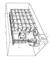
図4は、そのような自動倉庫3の構成の一例を示す概念図である。
自動倉庫3は、一例として、施錠可能な1つの部屋又は建屋に設けられる。施錠された内部においてスタッカクレーン4が制御装置41の制御下で無人運転される。安全のためスタッカクレーン4が停止している状態で、作業者はドア1から自動倉庫3に出入りする。
FIG. 4 is a conceptual diagram showing an example of the configuration of such an
As an example, the
ドア1とドア枠2には、それぞれ上述したドアスイッチシステムを備える鍵本体部10と受け金具20とが設けられる。ドアスイッチシステムは、スタッカクレーン4を非常停止させるためのインターロックシステムに用いられる。
The
受け金具20に設けられる検出器は、施錠状態が検出されている間、信号線29を通して制御装置41へ施錠信号を出力する。制御装置41は、この施錠信号が与えられている限り、スタッカクレーン4を通常に制御する。
The detector provided in the metal fitting 20 outputs a locking signal to the
検出器は、施錠状態が検出されなくなると、施錠信号の出力を停止する。制御装置41は、施錠信号が途切れることにより、スタッカクレーン4を非常停止させる。
When the locked state is no longer detected, the detector stops outputting the locking signal. The
この構成によれば、ドアスイッチシステムの無効化が困難であるために、作業者は安全上必要なオーバヘッドを不正に省くことができず、その結果、作業者の安全を良好に保つことでできる。 According to this configuration, since it is difficult to invalidate the door switch system, the worker cannot illegally omit the overhead necessary for safety, and as a result, the worker's safety can be kept good. .
なお、このようなインターロックシステムを、自動倉庫以外に適用することももちろん可能である。例えば、危険源となり得る工作機械を自動運転している部屋又は建屋において、入り口の施錠が検出されない場合に、工作機械を非常停止させるために用いることもできる。 Of course, such an interlock system can be applied to other than automatic warehouses. For example, in a room or a building in which a machine tool that can be a danger source is automatically operated, the machine tool can be used to make an emergency stop when an entrance lock is not detected.
次に、引き戸システムに適合するドアスイッチシステムの変形例について説明する。
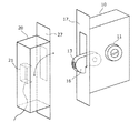
図5は、この変形例におけるドアスイッチシステムの一例を示す構成図である。
Next, a modified example of the door switch system suitable for the sliding door system will be described.
FIG. 5 is a configuration diagram showing an example of a door switch system in this modification.
このドアスイッチシステムは、図1(A)に示されるデッドボルト12を、鉤部材16に変更すると共に、受け金具20のフロント面27における孔の形状を変更することによって構成される。ラッチボルト19及び折り畳みノブ18は省略される。
This door switch system is configured by changing the
鉤部材16は、鍵本体部10に回動可能に取り付けられ、キーシリンダ11に挿入されたキーに加えられる回動力によって鍵本体部10のフロント面17から出没する。鉤部材16がフロント面27に設けられる孔から受け金具20内へ進入し、受け金具20と係合することによって、施錠が行われる。
The
鉤部材16には、施錠された状態で磁気センサ21と対向する位置に磁石13が設けられる。磁石13は、鉤部材16の動きに伴って、図5に示される鎖線に沿って、磁気センサ21に接近し、また後退する。
The
磁気センサ21は、鉤部材16が受け金具20内へ進入している場合と退出している場合とで、磁石13の位置の違いから期待されるそれぞれの磁場を検出することによって、施錠状態を検出する。
The
以上説明した構成によれば、鉤部材16を用いることにより引き戸システムに適合し、なおかつ、上述の説明と同様に、小型で耐久性が高く無効化が困難なドアスイッチシステムが得られる。
According to the configuration described above, it is possible to obtain a door switch system that is compatible with the sliding door system by using the
本発明に係るドアスイッチシステムは、例えば自動倉庫や工作機械のインターロックシステムを初めとして、ドアの施錠状態を検出して所定の制御を行う制御システムに広く利用できる。 The door switch system according to the present invention can be widely used in a control system that detects a locked state of a door and performs predetermined control, such as an automatic warehouse or an interlock system of a machine tool.
1 ドア
2 ドア枠
3 自動倉庫
4 スタッカクレーン
10 鍵本体部
11 キーシリンダ
12 デッドボルト
13 磁石
14 磁石アレイ
15 無線IDタグ
16 鉤部材
17 フロント面
18 折り畳みノブ
19 ラッチボルト
20 受け金具
21 磁気センサ
22 磁気センサアレイ
23 無線IDタグリーダ
27 フロント面
29 信号線
41 制御装置
91 錠本体部
92 受け金具
93 スライドキー
94 保護金具
95 センサスイッチ
DESCRIPTION OF
Claims (4)
前記可動部材及び前記ドア枠内のうちの一方に、周囲の電磁場を変化させる被検出体を備え、
他方に、前記可動部材が前記ドア枠内へ進入している場合に期待される電磁場を前記被検出体に接触することなく検出する検出器を備える
ことを特徴とするドアスイッチシステム。 A door switch system that detects a locked state of a door system that is locked when a movable member that is removably attached to the door enters the door frame,
One of the movable member and the door frame is provided with a detected object that changes the surrounding electromagnetic field,
On the other hand, a door switch system comprising: a detector that detects an electromagnetic field expected when the movable member enters the door frame without contacting the detected object.
前記検出器は無線タグリーダである
ことを特徴とする請求項1に記載のドアスイッチシステム。 The detected object is a wireless tag;
The door switch system according to claim 1, wherein the detector is a wireless tag reader.
前記検出器は磁気センサである
ことを特徴とする請求項1に記載のドアスイッチシステム。 The detected object is a magnet,
The door switch system according to claim 1, wherein the detector is a magnetic sensor.
前記磁気センサは、個々に磁場方向を検出可能な複数の磁気センサを配列してなる磁気センサアレイである
ことを特徴とする請求項3に記載のドアスイッチシステム。 The magnet is a magnet array in which a plurality of magnet pieces are arranged in a predetermined magnetic polarity order,
The door switch system according to claim 3, wherein the magnetic sensor is a magnetic sensor array in which a plurality of magnetic sensors capable of individually detecting a magnetic field direction are arranged.
Priority Applications (1)
| Application Number | Priority Date | Filing Date | Title |
|---|---|---|---|
| JP2007168059A JP4623058B2 (en) | 2007-06-26 | 2007-06-26 | Door switch system |
Applications Claiming Priority (1)
| Application Number | Priority Date | Filing Date | Title |
|---|---|---|---|
| JP2007168059A JP4623058B2 (en) | 2007-06-26 | 2007-06-26 | Door switch system |
Publications (2)
| Publication Number | Publication Date |
|---|---|
| JP2009007771A true JP2009007771A (en) | 2009-01-15 |
| JP4623058B2 JP4623058B2 (en) | 2011-02-02 |
Family
ID=40323125
Family Applications (1)
| Application Number | Title | Priority Date | Filing Date |
|---|---|---|---|
| JP2007168059A Expired - Fee Related JP4623058B2 (en) | 2007-06-26 | 2007-06-26 | Door switch system |
Country Status (1)
| Country | Link |
|---|---|
| JP (1) | JP4623058B2 (en) |
Cited By (6)
| Publication number | Priority date | Publication date | Assignee | Title |
|---|---|---|---|---|
| GB2505003A (en) * | 2012-08-18 | 2014-02-19 | Mark Gray | Fenestration alarm contact sensor for determining a locked and unlocked configuration |
| CN104423369A (en) * | 2013-09-05 | 2015-03-18 | 洛克威尔自动控制技术股份有限公司 | System and method for improving a sensing ability of an interlock switch system |
| KR20200108855A (en) * | 2018-01-22 | 2020-09-21 | 아싸 아브로이 에이비 | Strike plate assembly |
| JP7025933B2 (en) | 2018-01-12 | 2022-02-25 | 株式会社アルファ | Locker box |
| KR20230051986A (en) * | 2021-10-12 | 2023-04-19 | (주) 솔리티 | Striker for door lock |
| GB2644674A (en) * | 2024-04-12 | 2026-05-20 | Assa Abloy Ltd | Lock and switch assemblies |
Citations (4)
| Publication number | Priority date | Publication date | Assignee | Title |
|---|---|---|---|---|
| JPS61257581A (en) * | 1985-05-10 | 1986-11-15 | 五反田 基博 | Magnetic pole arrangement reading apparatus |
| JPS6483777A (en) * | 1987-09-26 | 1989-03-29 | Matsushita Electric Works Ltd | Locking release detection system |
| JPH10184123A (en) * | 1996-12-26 | 1998-07-14 | Miwa Lock Co Ltd | Locking confirmation device |
| JP2001032584A (en) * | 1999-07-23 | 2001-02-06 | Denso Corp | Locking and unlocking controller making use of non- contact ic card |
-
2007
- 2007-06-26 JP JP2007168059A patent/JP4623058B2/en not_active Expired - Fee Related
Patent Citations (4)
| Publication number | Priority date | Publication date | Assignee | Title |
|---|---|---|---|---|
| JPS61257581A (en) * | 1985-05-10 | 1986-11-15 | 五反田 基博 | Magnetic pole arrangement reading apparatus |
| JPS6483777A (en) * | 1987-09-26 | 1989-03-29 | Matsushita Electric Works Ltd | Locking release detection system |
| JPH10184123A (en) * | 1996-12-26 | 1998-07-14 | Miwa Lock Co Ltd | Locking confirmation device |
| JP2001032584A (en) * | 1999-07-23 | 2001-02-06 | Denso Corp | Locking and unlocking controller making use of non- contact ic card |
Cited By (9)
| Publication number | Priority date | Publication date | Assignee | Title |
|---|---|---|---|---|
| GB2505003A (en) * | 2012-08-18 | 2014-02-19 | Mark Gray | Fenestration alarm contact sensor for determining a locked and unlocked configuration |
| CN104423369A (en) * | 2013-09-05 | 2015-03-18 | 洛克威尔自动控制技术股份有限公司 | System and method for improving a sensing ability of an interlock switch system |
| US10210682B2 (en) | 2013-09-05 | 2019-02-19 | Rockwell Automation Technologies, Inc. | Systems and methods for improving a sensing ability of an interlock switch system |
| JP7025933B2 (en) | 2018-01-12 | 2022-02-25 | 株式会社アルファ | Locker box |
| KR20200108855A (en) * | 2018-01-22 | 2020-09-21 | 아싸 아브로이 에이비 | Strike plate assembly |
| KR102547132B1 (en) | 2018-01-22 | 2023-06-23 | 아싸 아브로이 에이비 | striking plate assembly |
| KR20230051986A (en) * | 2021-10-12 | 2023-04-19 | (주) 솔리티 | Striker for door lock |
| KR102570147B1 (en) * | 2021-10-12 | 2023-08-25 | (주)솔리티 | Striker for door lock |
| GB2644674A (en) * | 2024-04-12 | 2026-05-20 | Assa Abloy Ltd | Lock and switch assemblies |
Also Published As
| Publication number | Publication date |
|---|---|
| JP4623058B2 (en) | 2011-02-02 |
Similar Documents
| Publication | Publication Date | Title |
|---|---|---|
| JP4623058B2 (en) | Door switch system | |
| CN205743311U (en) | A kind of door lock state testing agency | |
| US11702863B2 (en) | Door handing assembly for electromechanical locks | |
| US20090066320A1 (en) | Deadbolt sensor for security systems | |
| US20110057788A1 (en) | Apparatus and Method For Determining Tampering With A Movable Barrier | |
| US12258795B2 (en) | Motor vehicle lock | |
| US11953644B2 (en) | Switch cabinet with a switch cabinet door having a door status sensor | |
| US12247416B2 (en) | Electromechanical lock assembly | |
| WO2015029351A1 (en) | Fixture open/closed detection device and fixture locked/unlocked detection device using same | |
| WO2006016826A3 (en) | Electrical lock with status indicator | |
| WO2017008104A1 (en) | A magnetic field generator for use in a locking arrangement | |
| JP2013008283A (en) | Fitting locking/unlocking detector | |
| JPH0194561U (en) | ||
| KR102531348B1 (en) | Latch assembly for door-lock | |
| US8699200B2 (en) | Secure non-contact switch | |
| US3968483A (en) | Burglar and fire alarm system | |
| WO2019141470A1 (en) | Striking plate assembly | |
| EP1896678B1 (en) | A monitoring system for a window or door | |
| KR200300365Y1 (en) | Door locking system for monitoring door to be opened and closed | |
| JP2005282073A (en) | Locking omission preventing system | |
| KR200316155Y1 (en) | Door lock Apparatus | |
| ES2288567T3 (en) | DOOR HANDLE WITH PRESENCE SENSOR. | |
| CN224017003U (en) | Door lock capable of reminding people not to close door | |
| JP5345308B2 (en) | Prying prevention system | |
| KR20080000070A (en) | How to control the opening and closing of the trunk using smart key and smart key and glove box locking device |
Legal Events
| Date | Code | Title | Description |
|---|---|---|---|
| A977 | Report on retrieval |
Free format text: JAPANESE INTERMEDIATE CODE: A971007 Effective date: 20100714 |
|
| A131 | Notification of reasons for refusal |
Free format text: JAPANESE INTERMEDIATE CODE: A131 Effective date: 20100720 |
|
| A521 | Written amendment |
Free format text: JAPANESE INTERMEDIATE CODE: A523 Effective date: 20100831 |
|
| TRDD | Decision of grant or rejection written | ||
| A01 | Written decision to grant a patent or to grant a registration (utility model) |
Free format text: JAPANESE INTERMEDIATE CODE: A01 Effective date: 20101005 |
|
| A01 | Written decision to grant a patent or to grant a registration (utility model) |
Free format text: JAPANESE INTERMEDIATE CODE: A01 |
|
| A61 | First payment of annual fees (during grant procedure) |
Free format text: JAPANESE INTERMEDIATE CODE: A61 Effective date: 20101018 |
|
| R150 | Certificate of patent or registration of utility model |
Free format text: JAPANESE INTERMEDIATE CODE: R150 |
|
| FPAY | Renewal fee payment (event date is renewal date of database) |
Free format text: PAYMENT UNTIL: 20131112 Year of fee payment: 3 |
|
| FPAY | Renewal fee payment (event date is renewal date of database) |
Free format text: PAYMENT UNTIL: 20131112 Year of fee payment: 3 |
|
| R250 | Receipt of annual fees |
Free format text: JAPANESE INTERMEDIATE CODE: R250 |
|
| R250 | Receipt of annual fees |
Free format text: JAPANESE INTERMEDIATE CODE: R250 |
|
| R250 | Receipt of annual fees |
Free format text: JAPANESE INTERMEDIATE CODE: R250 |
|
| R250 | Receipt of annual fees |
Free format text: JAPANESE INTERMEDIATE CODE: R250 |
|
| LAPS | Cancellation because of no payment of annual fees |