JP2009007772A - Door panel - Google Patents
Door panel Download PDFInfo
- Publication number
- JP2009007772A JP2009007772A JP2007168077A JP2007168077A JP2009007772A JP 2009007772 A JP2009007772 A JP 2009007772A JP 2007168077 A JP2007168077 A JP 2007168077A JP 2007168077 A JP2007168077 A JP 2007168077A JP 2009007772 A JP2009007772 A JP 2009007772A
- Authority
- JP
- Japan
- Prior art keywords
- door panel
- pair
- members
- glass plate
- main body
- Prior art date
- Legal status (The legal status is an assumption and is not a legal conclusion. Google has not performed a legal analysis and makes no representation as to the accuracy of the status listed.)
- Granted
Links
Images


Landscapes
- Securing Of Glass Panes Or The Like (AREA)
Abstract
【課題】ドアパネル本体の強度を確保しつつも製造時における作業効率が高く、且つ、採光板の交換が容易なドアパネルを提供することを目的とするものである。
【解決手段】窓部11が形成されたドアパネル本体12と、窓部11に配設されたガラス板13と、窓部11の周縁部に配設されるとともにガラス板13を保持する保持部材20とを備えたドアパネル10において、ドアパネル本体11にはその外縁部のみに補強枠材が設けられ、保持部材20は一対のモール材20a,20bにより構成され、一対のモール材20a,20bはドアパネル本体11の両面側から周縁部を挟み込んだ状態で互いに結合されて周縁部に取り付けけられるとともに、ガラス板13は、一対のモール材20a,20bの間で挟みこまれて保持されている
【選択図】図3An object of the present invention is to provide a door panel that has high work efficiency at the time of manufacture while ensuring the strength of the door panel body and that allows easy replacement of a daylighting plate.
A door panel body 12 in which a window portion 11 is formed, a glass plate 13 provided in the window portion 11, and a holding member 20 provided on a peripheral portion of the window portion 11 and holding the glass plate 13. The door panel main body 11 is provided with a reinforcing frame member only on the outer edge portion thereof, the holding member 20 is composed of a pair of molding materials 20a and 20b, and the pair of molding materials 20a and 20b is a door panel main body. 11 are joined to each other with the peripheral edge sandwiched from both sides thereof, and attached to the peripheral edge, and the glass plate 13 is sandwiched and held between the pair of molding materials 20a and 20b. Figure 3
Description
本発明はドアパネル本体の窓部に採光板が配設されたドアパネルに関するものである。 The present invention relates to a door panel in which a daylighting plate is disposed in a window portion of a door panel body.
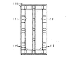
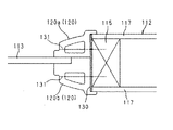
従来から、ドアパネル本体に窓部を形成し、当該窓部にガラス板を配設したドアパネルが多数知られている(例えば特許文献1参照)。図6は従来のドアパネル本体の内部構造を示す正面図であり、図7はドアパネル本体へのガラス板の取付部近傍における水平方向断面の拡大図である。 Conventionally, many door panels in which a window portion is formed in a door panel body and a glass plate is disposed on the window portion are known (see, for example, Patent Document 1). FIG. 6 is a front view showing the internal structure of a conventional door panel main body, and FIG. 7 is an enlarged view of a horizontal cross section in the vicinity of the attachment portion of the glass plate to the door panel main body.
従来のドアパネル本体112では、その外縁部及び窓部111の周縁部に芯材を設けてドアパネル本体112の補強枠材115が形成されている。そして、この補強枠材115の両面に化粧板117を貼り付けることによりドアパネル本体112が形成されている。また、ドアパネル本体112における窓部111の周縁部には保持部材120が配設されている。保持部材120は窓部111に配設されるガラス板113を保持するためのものであり、一対の長尺状のモール材120a,120bで構成されている。一対のモール材120a,120bはドアパネル本体112の両面側から周縁部を挟み込むようにして配設されている。窓部111に配設されるガラス板113は、この一対のモール材120a,120b間で保持されてドアパネル本体112に取り付けられている。
ところで従来のドアパネル本体112では、その外縁部と窓部111の周縁部に補強枠材115を配設することで強度を確保していた。しかしながら、ドアパネル本体112を製造するにあたり、ドアパネル本体112の外縁部及び窓部111の周縁部の両方に補強枠材115を配設した上で化粧板117を貼り付けることは、ドアパネル本体112を製造する際の作業工数が増大する原因となる。
By the way, in the conventional door panel main body 112, intensity | strength was ensured by arrange | positioning the
また、保持部材120を構成するモール材120a,120bは、窓部111の周縁部に配設されている補強枠材115に接着剤130やタッカー131等で固定されていた。そのため、一度ドアパネル本体112にモール材120a,120bを取り付けると、モール材120a,120bをドアパネル本体112から取り外すことが困難であった。その結果、ガラス板113を交換しようとする場合に容易にモール材120a,120bを取り外すことができなかった。
Further, the molding materials 120a and 120b constituting the
本発明は、上記問題に鑑みなされたものであり、ドアパネル本体に形成された窓部に採光板が配設されたドアパネルにおいて、ドアパネル本体の強度を確保しつつも製造時における作業効率が高いドアパネルを提供することを目的とする。また、本発明は、製造後において採光板の交換が容易なドアパネルを提供することを目的とする。 The present invention has been made in view of the above problems, and in a door panel in which a daylighting plate is disposed in a window portion formed in the door panel body, the door panel has high work efficiency at the time of manufacturing while ensuring the strength of the door panel body. The purpose is to provide. Another object of the present invention is to provide a door panel in which a lighting plate can be easily replaced after manufacturing.
上記課題を解決するために、請求項1記載の発明では、窓部が形成されたドアパネル本体と、当該窓部に配設された採光板と、前記窓部の周縁部に配設されるとともに前記採光板を保持する一対の保持部材とを備えたドアパネルにおいて、前記ドアパネル本体にはその外縁部のみに補強枠材が設けられ、前記一対の保持部材は前記ドアパネル本体の両面側から前記周縁部を挟み込んだ状態で互いに結合されて前記周縁部に取り付けられ前記ドアパネル本体の補強枠材として機能するとともに、前記採光板は、前記一対の保持部材の間で挟みこまれて保持されていることを特徴としている。
In order to solve the above-mentioned problem, in the invention according to
ドアパネル本体の補強枠材をドアパネル本体の外縁部のみに設けることにより、ドアパネル本体を製造する際の工数を低減することが可能となるので、ドアパネルの製造時における作業効率を高めることが可能となる。また、本発明のドアパネルにおいては、一対のモール材がドアパネル本体の窓部の周縁部を挟み込むようにして取り付けられる。これにより、一対のモール材に窓部の周縁部における補強枠材としての機能を代用させることができる。この結果、ドアパネル本体自体には窓部の周縁部に補強枠材を用いない構成とした場合においてもドアパネル全体としての強度を確保することが可能となる。 By providing the door panel body reinforcement frame material only on the outer edge of the door panel body, it is possible to reduce the man-hours when manufacturing the door panel body, and thus it is possible to increase the work efficiency at the time of manufacturing the door panel. . Moreover, in the door panel of this invention, a pair of molding materials are attached so that the peripheral part of the window part of a door panel main body may be inserted | pinched. Thereby, a function as a reinforcement frame material in the peripheral part of a window part can be substituted for a pair of molding materials. As a result, even when the door panel main body itself is configured not to use a reinforcing frame member at the peripheral edge portion of the window portion, it is possible to ensure the strength of the door panel as a whole.
また、本発明のドアパネルでは、採光板は一対の保持部材により挟み込まれて保持されている。そしてこの一対の保持部材は、窓部の周縁部を挟み込んだ状態で互いに結合されることにより周縁部に取り付けられている。すなわち、本発明では、一対の保持部材間の結合を解除すれば保持部材を窓部の周縁部から取り外すことが可能である。この結果、ドアパネルの製造後に採光板を交換しようとする場合においても、ドアパネルの本体から保持部材を取り外すことにより容易に採光板を交換することが可能である。 In the door panel of the present invention, the daylighting plate is sandwiched and held by a pair of holding members. The pair of holding members are attached to the peripheral portion by being coupled to each other while sandwiching the peripheral portion of the window portion. That is, in the present invention, if the coupling between the pair of holding members is released, the holding member can be removed from the peripheral portion of the window portion. As a result, even when the lighting plate is to be replaced after the door panel is manufactured, it is possible to easily replace the lighting plate by removing the holding member from the main body of the door panel.
請求項2に記載の発明では、前記ドアパネル本体は、その外縁部の補強枠体の内部に補強面材を設けるとともに当該面材の両面に化粧板を設けて構成されていることを特徴としている。ドアパネル本体の内部に補強面材を設けることにより、ドアパネル本体の強度を高めることが可能となる。 In the invention according to claim 2, the door panel main body is characterized in that a reinforcing face member is provided inside a reinforcing frame body at an outer edge portion thereof and a decorative plate is provided on both sides of the face member. . By providing the reinforcing face material inside the door panel body, the strength of the door panel body can be increased.
請求項3に記載の発明は、前記一対の保持部材は嵌合により結合されていることを特徴としている。これにより、一対のモール材の結合及びその解除を容易に行うことが可能である。 The invention according to claim 3 is characterized in that the pair of holding members are coupled by fitting. Thereby, it is possible to easily couple and release the pair of molding materials.
請求項4に記載の発明は、前記一対の保持部材の少なくとも一方は、前記周縁部を挟み込むための第1部材と前記採光板を挟み込むための第2部材とに分割可能に構成されており、前記第1部材と前記第2部材とは互いに嵌合されて一体化されていることを特徴としている。 The invention according to claim 4 is configured so that at least one of the pair of holding members can be divided into a first member for sandwiching the peripheral portion and a second member for sandwiching the lighting plate, The first member and the second member are fitted and integrated with each other.
これによると、少なくとも一方のモール材は分割可能に構成されている。このため、一対の保持部材のうち、一方のモール材は第1部材のみが取り付けられた状態とし、他方のモール材は周縁部を挟み込む部分と採光板を挟み込む部分がともに窓部の周縁部に取り付けられた状態とすることが可能である。この結果、第1部材のみが取り付けられた一方のモール材側から他方のモール材に採光板を支持させ、その後、一方のモール材の第2部材を第1部材と嵌合させるとともに一対のモール材間で採光板を挟み込むことが可能となる。すなわち、採光板を一のモール材で支持させた状態で他のモール材を取り付けることが可能となるので、採光板を取り付ける際の作業性を向上することが可能となる。 According to this, at least one molding material is comprised so that division | segmentation is possible. For this reason, of the pair of holding members, one molding material is in a state in which only the first member is attached, and the other molding material has both the portion sandwiching the peripheral portion and the portion sandwiching the lighting plate at the peripheral portion of the window portion. It can be in the attached state. As a result, the daylighting plate is supported from one molding material side to which only the first member is attached to the other molding material, and then the second member of one molding material is fitted to the first member and the pair of moldings. It is possible to sandwich the lighting plate between the materials. That is, since it becomes possible to attach another molding material in a state where the lighting plate is supported by one molding material, it is possible to improve workability when attaching the lighting plate.
請求項5に記載の発明では、前記第1部材に対する前記第2部材の嵌合方向は、前記第2部材が前記採光板に近接する方向であることを特徴としている。これにより、第2部材を第1部材に嵌合させる程度を大きくするほど、一対の保持部材による採光板の保持の確実性を向上させることが可能となる。 The invention according to claim 5 is characterized in that the fitting direction of the second member with respect to the first member is a direction in which the second member approaches the daylighting plate. Thereby, it becomes possible to improve the certainty of holding of the daylighting plate by the pair of holding members as the degree of fitting the second member to the first member is increased.
本発明のドアパネルでは、ドアパネル本体の外縁部のみに補強枠材を設ける構成としたので、製造時における作業効率を高めることが可能となる。そして、ドアパネル本体自体においては窓部の周縁部に補強枠材を設けない代わりに、窓部の周縁部を挟み込むように一対のモール材を設けた。この結果、当該モール材に補強枠材としての機能を代用させることができ、ドアパネル全体としての強度も確保することが可能となる。また、本発明のドアパネルでは、一対の保持部材の結合を解除すれば保持部材を周縁部から取り外すことが可能である。このため、ドアパネルの製造後に採光板を交換しようとする場合においても、ドアパネルの本体から保持部材を取り外すことにより容易に採光板を交換することが可能である。 In the door panel according to the present invention, the reinforcing frame member is provided only on the outer edge of the door panel body, so that the working efficiency at the time of manufacture can be increased. In the door panel main body itself, a pair of molding materials is provided so as to sandwich the peripheral edge of the window, instead of providing the reinforcing frame at the peripheral edge of the window. As a result, the function as a reinforcing frame member can be substituted for the molding material, and the strength of the door panel as a whole can be ensured. Moreover, in the door panel of this invention, if the coupling | bonding of a pair of holding member is cancelled | released, it is possible to remove a holding member from a peripheral part. For this reason, even when it is going to replace a lighting plate after manufacture of a door panel, it is possible to replace | exchange a lighting plate easily by removing a holding member from the main body of a door panel.
[第1実施形態]
以下、本発明に係るドアパネルの構造を具体化した第1実施形態を図面に基づいて説明する。図1は本実施形態に係るドアパネルの正面図であり、図2は本実施形態に係るドアパネル本体における製造途中の内部構造を示す図である。また、図3は本実施形態に係るドアパネル本体へのガラス板の取付部近傍における水平方向断面の拡大図であり、図4は窓部へのガラス板の取り付け手順を示す図である。
[First Embodiment]
Hereinafter, a first embodiment in which the structure of a door panel according to the present invention is embodied will be described with reference to the drawings. FIG. 1 is a front view of a door panel according to the present embodiment, and FIG. 2 is a diagram showing an internal structure in the middle of manufacture of the door panel body according to the present embodiment. FIG. 3 is an enlarged view of a horizontal cross section in the vicinity of a glass plate attachment portion to the door panel body according to the present embodiment, and FIG. 4 is a diagram showing a procedure for attaching the glass plate to the window portion.
図1に示すように、本実施形態のドアパネル10は、窓部11が形成されたドアパネル本体12と、窓部11に配設される採光板としてのガラス板13と、ドアパネル本体12に取り付けられてガラス板13を保持する保持部材20とを含んで構成されている。
As shown in FIG. 1, the
図2に示すように、ドアパネル本体12は、芯材としての補強枠材15と、補強枠材15内に配設された補強面材としてのハニカムペーパー16と、ハニカムペーパー16の両面側に貼られた化粧板17とを有している。補強枠材15は、2本の縦材18の端部間のそれぞれに横材19を設けてドアパネル10の外形に対応した大きさの矩形状に形成されている。ハニカムペーパー16は多数のハニカム状セルが並べられた板状の構造体であり、各セルはハニカムペーパー16の厚さ方向に開口している。
As shown in FIG. 2, the
保持部材20は例えばABS樹脂等で形成され、長尺状の一対のモール材20a,20bで構成されている。図3に示すように、保持部材20は一対のモール材20a,20bでドアパネル本体12の両面側から窓部11の周縁部11aを挟み込むようにして配置されている。対をなすモール材20a,20bの各々は、ドアパネル本体12における窓部11の周縁部11aに取り付けられる第1部材21a,21bとガラス板13を挟持する第2部材22a,22bとに分割可能に構成されている。
The
対をなす第1部材21a,21bの各々は、窓部11の内周面部11bに対向して配設される基部23a,23bと窓部11の周縁部11aにおいて化粧板17の端部に係止される係止片部24a,24bとを有している。また、一方の第1部材21aの基部23aには凸部25aが形成され、他方の第1部材21bの基部23bには凸部25aと嵌合する凹部25bが形成されている。
Each of the paired
係止片部24a,24bを周縁部11aに係止させた状態で凸部25aと凹部25bとを互いに嵌合させることにより、両第1部材21a,21bが一体化されるとともに一対の第1部材21a,21bの係止片部24a,24b間で周縁部11aが挟みこまれている。この結果、一体化された一対の第1部材21a,21bが周縁部11aに取り付けられている。一対の第1部材21a,21bは、窓部の周縁部11aを囲むように配設されることで窓部11の周縁部11aにおいてドアパネル本体12の補強枠材として機能している。
By fitting the
一対の第2部材22a,22bの各々は一対の第1部材21a,21bの各々に固定されている。両者の固定は、第1部材21a,21bに形成された凹部26a,26bに第2部材22a,22bに形成された凸部27a,27bを嵌合させることでなされている。一対の第1部材21a,21bに形成された凹部26a,26bは、第2部材22a,22bに形成された凸部27a,27bを凹部26a,26bに深く嵌合させるほど両第2部材22a,22b間の距離が小さくなるように設けられている。具体的には、図3に示す状態において、両凹部26a,26bは、それらの穿設方向への仮想延長線が窓部11の内周面部11b側で交差するように形成されている。すなわち、第2部材22a,22bの凸部27a,27bは、窓部11の内側から外側に向けた方向であってガラス板13の仮想延長面に対して斜めに交差する方向に押し込まれて第1部材21a,21bの凹部26a,26bに嵌合されている。
Each of the pair of
一方の第2部材22aには、面で当接してガラス板13を挟持するための挟持部28aが形成されている。また、他方の第2部材22bには、その窓部11の内周側端部のみにおいて接触してガラス板13を挟持する挟持部28bがガラス板13側に突出して形成されている。そして、挟持部28bでガラス板13が挟持された際には、挟持部28bの第1部材21a側において、第2部材22bとガラス板13との間に空隙が形成される。
One of the
挟持部28bの第1部材21a側には、薄いゴム材29が設けられている。ゴム材29はガラス板13が一対のモール材20a,20b間で挟持された際にガラス板13に当接するように設けられており、ガラス板13の微小振動を抑制するためのものである。ゴム材29は窓部11の内方からは挟持部28bで隠される位置に設けられている。また、第2部材22bとガラス板13との間における空隙に突出するように設けられるので空隙部分で変形可能であり、良好にガラス板13に当接できるようになっている。
A
次に、本実施形態におけるドアパネル10を製造する工程を説明する。まず、補強枠材15内にハニカムペーパー16を配設する(図2参照)。そして、窓部11に対応する位置のハニカムペーパー16をくり抜き、その後ハニカムペーパー16の両面に化粧板17を貼り付けることによって、ドアパネル本体12が形成される。なお、補強枠材15内のハニカムペーパー16の両面に化粧板17を貼り付けた後に、窓部11に対応する部分をくり抜いてドアパネル本体12を形成してもよい。
Next, a process for manufacturing the
次に、ドアパネル10に形成された窓部11にガラス板13が取り付けられる。これについて図4(a)から(e)を用いて説明する。まず、図4(a)に示すように、ドアパネル本体12の両面側から窓部11の周縁部11aを挟み込むようにして、一対の第1部材21a,21bを配置する。そして、第1部材21aの一方に形成された凸部25aと他方に形成された凹部25bとを互いに嵌合させることにより、両第1部材21a,21bを一体化する。そして、両第1部材21a,21b間で窓部11の周縁部11aを挟持させることにより両第1部材21a,21bを周縁部11aに取り付ける。
Next, the
次に図4(b)に示すように、周縁部11aに取り付けられた一の第1部材21aの凹部26aに一の第2部材22aの凸部27aを嵌合させる。そして、図4(c)に示すようにガラス板13を一の第2部材22aの挟持部28aで支持させ、その後図4(d)に示すように他の第2部材22bの凸部27bを他の第1部材21bの凹部26bに嵌合させる。この結果、図4(e)に示すように、一対のモール材20a,20b間で挟持されてガラス板13が窓部11の周縁部11aに取り付けられる。
Next, as shown in FIG. 4B, the convex portion 27a of one
以上詳述した本実施の形態によれば、以下の優れた効果が得られる。 According to the embodiment described above in detail, the following excellent effects can be obtained.
本実施形態のドアパネル10では、ドアパネル本体12の補強枠材は外縁部のみに設けられており窓部11の周縁部11aには設けられていない。そのため、ドアパネル本体12を製造する際の工数を低減することができ、効率的にドアパネル本体12を製造することが可能となる。また本実施形態のドアパネル10では、ドアパネル本体12における窓部11の周縁部11aを挟み込むように一対の第1部材21a,21bが取り付けられており、この一対の第1部材21a,21bは周縁部11aにおいて補強枠材としての機能を代用している。このため、ドアパネル本体12自体には窓部11の周縁部11aに補強枠材を設けずに構成されているが、ドアパネル10全体としての強度は確保することが可能である。
In the
本実施形態のドアパネル10では、ガラス板13を保持する保持部材20は、接着剤やタッカー等を用いることなく、一対の第1部材21a,21bの間に窓部11の周縁部11aを挟持させた状態で一対の第1部材21a,21bを互いに嵌合させて一体化することで、ドアパネル本体12に取り付けられている。このため、ガラス板13を交換する必要が生じた場合には、第1部材21a,21bを容易にドアパネル本体12から取り外すことが可能であり、ガラス板13の交換を容易に行うことが可能である。特に本実施形態では、一対の第1部材21a,21bは互いに嵌合させて一体化しているので、両者の一体化及び分割を容易に行うことが可能である。
In the
本実施形態のドアパネル10では、一対の保持部材20の各々を第1部材21a,21bと第2部材22a,22bに分割して構成している。そして、ガラス板13を一対の保持部材20間で挟持させる工程の前段階(図4(c)の段階)までで、一対の第1部材21a,21bが周縁部11aに取り付けられるとともに一の第2部材22aが一の第1部材21aに固定されている。この結果、ガラス板13を一対の第2部材22a,22b間に保持させようとする工程において、ガラス板13を一の第2部材22aで支持させながら他の第2部材22bを第1部材21bに嵌合させてガラス板13を挟持させることが可能となる。このため、第2部材22a,22b間でガラス板13を挟持させる際の作業性を向上することが可能となる。
In the
本実施形態のドアパネル10では、第1部材21a,21bに対する第2部材22a,22bの嵌合方向は、第2部材22a,22bを第1部材21a,21bに嵌合させる程度を大きくするほど、第2部材22a,22bがガラス板13に近接する方向とされている。これにより、第2部材22a,22bを第1部材21a,21bに嵌合させるほど両第2部材22a,22b間の間隔が小さくなり、より確実にガラス板13を挟持させることが可能となる。
In the
本実施形態のドアパネル10では、第1部材21a,21bの両凹部26a,26bは、それらの穿設方向への仮想延長線が窓部11の内周面部11b側で交差するように形成されている。すなわち、凸部27a,27bと凹部26a,26bとの間の嵌合方向に作用する力はガラス板13の板面に垂直な成分と平行な成分とに分解される。このため、凸部27a,27bと凹部26a,26bとの嵌合が緩んだ場合においても、その緩みによりガラス板の挟持強さの低減に直接影響する成分が抑制される。
In the
[第2実施形態]
次に本発明の第2実施形態について、図5に基づいて説明する。なお、第1実施形態と同一の構成については同一符号を付し、説明を省略する。
[Second Embodiment]
Next, a second embodiment of the present invention will be described with reference to FIG. In addition, about the structure same as 1st Embodiment, the same code | symbol is attached | subjected and description is abbreviate | omitted.
第1実施形態においては、保持部材20を構成する一対のモール材20a,20bの各々を、第1部材21a,21bと第2部材22a,22bとに分割可能に構成した。これに対して第2実施形態では、一対のモール材20a,20bの各々を一個の部材で構成する。すなわち、本実施形態における一対のモール材20a,20bの各々は、第1実施形態における第1部材21a,21bと第2部材22a,22bとが一体化された状態に形成されている。他の構成要素については、第1実施形態と同一である。
In the first embodiment, each of the pair of
本実施形態においても第1実施形態と同様に、ドアパネル本体12自体には窓部11の周縁部11aには補強枠材を設けていないので、ドアパネル本体12を製造する際の効率を向上することが可能である。また、一対のモール材20a,20bを窓部11の周縁部11aに取り付けることで、一対のモール材20a,20bに補強枠材としての機能を代用させることができ、ドアパネル本体12の強度を確保することが可能である。
Also in the present embodiment, as in the first embodiment, the door panel
本実施形態では、一対のモール材20a,20bを第1部材21a,21bと第2部材22a,22bとに分割可能とせずに一体化した構成とした。これにより、部品点数を低減することが可能となるとともに、ガラス板13を窓部11に取り付ける際の工数を低減することも可能となる。
In the present embodiment, the pair of
なお、一対のモール材20a,20bの一方のみ、第1部材21a,21bと第2部材22a,22bとに分割可能な構成としてもよい。これにより、部品点数の増大は抑止しつつ、ガラス板13を取り付ける際の作業性を向上することが可能となる。
In addition, it is good also as a structure which can be divided | segmented into
上記実施形態では、補強面材としてハニカムペーパー16を用いたが、補強面材はこれに限るものではなく、ウレタンボード等を用いることも可能である。
In the above embodiment, the
上記実施形態では、一対のモール材20a,20bは互いに嵌合することで一体化させたが、両者の一体化は接着剤やビス等を用いて行ってもよい。
In the above embodiment, the pair of
10…ドアパネル、11…窓部、12…ドアパネル本体、13…ガラス板、15…補強枠材、16…ハニカムペーパー、17…化粧板、18…縦材、19…横材、20…保持部材、21a,21b…第1部材、22a,22b…第2部材、23a,23b…基部、24a,24b…係止片部、25a…凸部、25b…凹部、26a,26b…凹部、27a,27b…凸部、28a,28b…挟持部、29…ゴム材。
DESCRIPTION OF
Claims (5)
前記ドアパネル本体にはその外縁部のみに補強枠材が設けられ、
前記一対の保持部材は前記ドアパネル本体の両面側から前記周縁部を挟み込んだ状態で互いに結合されて前記周縁部に取り付けられ前記ドアパネル本体の補強枠材として機能するとともに、
前記採光板は、前記一対の保持部材の間で挟みこまれて保持されていることを特徴とするドアパネル。 In a door panel provided with a door panel body in which a window is formed, a daylighting plate disposed in the window, and a pair of holding members that are disposed on a peripheral portion of the window and hold the daylighting plate. ,
The door panel body is provided with a reinforcing frame material only at the outer edge portion thereof,
The pair of holding members are connected to each other in a state of sandwiching the peripheral edge from both sides of the door panel main body and attached to the peripheral edge and function as a reinforcing frame member of the door panel main body.
The door plate, wherein the daylighting plate is sandwiched and held between the pair of holding members.
前記第1部材と前記第2部材とは互いに嵌合されて一体化されていることを特徴とする請求項1から請求項3のいずれか一項に記載のドアパネル。 At least one of the pair of holding members is configured to be divided into a first member for sandwiching the peripheral edge portion and a second member for sandwiching the lighting plate,
The door panel according to any one of claims 1 to 3, wherein the first member and the second member are fitted and integrated with each other.
Priority Applications (1)
| Application Number | Priority Date | Filing Date | Title |
|---|---|---|---|
| JP2007168077A JP4941981B2 (en) | 2007-06-26 | 2007-06-26 | Door panel |
Applications Claiming Priority (1)
| Application Number | Priority Date | Filing Date | Title |
|---|---|---|---|
| JP2007168077A JP4941981B2 (en) | 2007-06-26 | 2007-06-26 | Door panel |
Publications (2)
| Publication Number | Publication Date |
|---|---|
| JP2009007772A true JP2009007772A (en) | 2009-01-15 |
| JP4941981B2 JP4941981B2 (en) | 2012-05-30 |
Family
ID=40323126
Family Applications (1)
| Application Number | Title | Priority Date | Filing Date |
|---|---|---|---|
| JP2007168077A Expired - Fee Related JP4941981B2 (en) | 2007-06-26 | 2007-06-26 | Door panel |
Country Status (1)
| Country | Link |
|---|---|
| JP (1) | JP4941981B2 (en) |
Cited By (2)
| Publication number | Priority date | Publication date | Assignee | Title |
|---|---|---|---|---|
| WO2019036616A1 (en) * | 2017-08-18 | 2019-02-21 | Plastpro 2000, Inc. | Doors comprising glazed unit, and method of making the same |
| RU236546U1 (en) * | 2025-03-31 | 2025-08-12 | Максим Александрович Волков | Door with double glazing |
Citations (5)
| Publication number | Priority date | Publication date | Assignee | Title |
|---|---|---|---|---|
| JPS4429490Y1 (en) * | 1964-09-11 | 1969-12-05 | ||
| JPS5148332A (en) * | 1974-10-24 | 1976-04-26 | Mitsubishi Paper Mills Ltd | |
| JPS5550210A (en) * | 1978-10-06 | 1980-04-11 | Enshu Kogaku Seiki Kk | Telescope with distance measuring device |
| JPH0387491A (en) * | 1989-08-29 | 1991-04-12 | Fukuvi Chem Ind Co Ltd | Door |
| JP2001241270A (en) * | 2000-02-29 | 2001-09-04 | Sanwa Shutter Corp | Lightweight panel with window |
-
2007
- 2007-06-26 JP JP2007168077A patent/JP4941981B2/en not_active Expired - Fee Related
Patent Citations (5)
| Publication number | Priority date | Publication date | Assignee | Title |
|---|---|---|---|---|
| JPS4429490Y1 (en) * | 1964-09-11 | 1969-12-05 | ||
| JPS5148332A (en) * | 1974-10-24 | 1976-04-26 | Mitsubishi Paper Mills Ltd | |
| JPS5550210A (en) * | 1978-10-06 | 1980-04-11 | Enshu Kogaku Seiki Kk | Telescope with distance measuring device |
| JPH0387491A (en) * | 1989-08-29 | 1991-04-12 | Fukuvi Chem Ind Co Ltd | Door |
| JP2001241270A (en) * | 2000-02-29 | 2001-09-04 | Sanwa Shutter Corp | Lightweight panel with window |
Cited By (5)
| Publication number | Priority date | Publication date | Assignee | Title |
|---|---|---|---|---|
| WO2019036616A1 (en) * | 2017-08-18 | 2019-02-21 | Plastpro 2000, Inc. | Doors comprising glazed unit, and method of making the same |
| EP3669041A4 (en) * | 2017-08-18 | 2021-01-27 | Plastpro 2000, Inc. | DOORS INCLUDING A GLASS UNIT, AND CORRESPONDING MANUFACTURING PROCESS |
| US10968683B2 (en) | 2017-08-18 | 2021-04-06 | Plastpro 2000, Inc. | Doors comprising glazed unit, and method of making the same |
| US11473364B2 (en) | 2017-08-18 | 2022-10-18 | Plastpro 2000, Inc. | Doors comprising glazed unit, and method of making the same |
| RU236546U1 (en) * | 2025-03-31 | 2025-08-12 | Максим Александрович Волков | Door with double glazing |
Also Published As
| Publication number | Publication date |
|---|---|
| JP4941981B2 (en) | 2012-05-30 |
Similar Documents
| Publication | Publication Date | Title |
|---|---|---|
| US8031289B2 (en) | Optical sheet retaining tool and chassis for liquid crystal display device | |
| CN108367981B (en) | Laminated plate | |
| JP2014193721A (en) | Vehicular fully glass roof | |
| CN107813682A (en) | The structure of vehicle side door | |
| JP4941981B2 (en) | Door panel | |
| JP2003233059A (en) | Touch panel display | |
| CN111417571B (en) | Window glass and components including window glass | |
| CN103108797A (en) | Panel-joining structure | |
| CN207801848U (en) | Solar cell module | |
| CN101305316A (en) | Holder and frame for optical sheet for liquid crystal display device | |
| JP4572771B2 (en) | Support structure and support method for laminated plate member | |
| KR100408833B1 (en) | Door of composite aircraft and its manufacturing method | |
| WO2024114714A1 (en) | Car window trim strip connection structure | |
| CN100564714C (en) | Connection structures for connecting elements, especially glass elements | |
| JP5044526B2 (en) | door | |
| JP2007112377A (en) | Housing mounting structure | |
| CN116424078B (en) | Vehicle door outer water-cut installation mechanism, vehicle door outer water-cut assembly and vehicle door | |
| CN220809084U (en) | Vehicle door assembly and vehicle | |
| CN221722632U (en) | A high-strength laminated glass | |
| WO2012124532A1 (en) | Attachment structure for window glass | |
| JPH11336441A (en) | Door stop shape of toilet booth | |
| JP2006241755A (en) | Decorative plate | |
| JP7130565B2 (en) | Surface decorative material unit and door body | |
| CN111409708B (en) | An integrated rear spoiler assembly with ailerons | |
| EP1529918A1 (en) | Method of forming a glazed door, and glazed door |
Legal Events
| Date | Code | Title | Description |
|---|---|---|---|
| A621 | Written request for application examination |
Free format text: JAPANESE INTERMEDIATE CODE: A621 Effective date: 20081222 |
|
| A977 | Report on retrieval |
Free format text: JAPANESE INTERMEDIATE CODE: A971007 Effective date: 20110223 |
|
| A131 | Notification of reasons for refusal |
Free format text: JAPANESE INTERMEDIATE CODE: A131 Effective date: 20110301 |
|
| A521 | Written amendment |
Free format text: JAPANESE INTERMEDIATE CODE: A523 Effective date: 20110412 |
|
| A131 | Notification of reasons for refusal |
Free format text: JAPANESE INTERMEDIATE CODE: A131 Effective date: 20110802 |
|
| A521 | Written amendment |
Free format text: JAPANESE INTERMEDIATE CODE: A523 Effective date: 20110805 |
|
| TRDD | Decision of grant or rejection written | ||
| A711 | Notification of change in applicant |
Free format text: JAPANESE INTERMEDIATE CODE: A712 Effective date: 20120111 |
|
| A01 | Written decision to grant a patent or to grant a registration (utility model) |
Free format text: JAPANESE INTERMEDIATE CODE: A01 Effective date: 20120124 |
|
| A01 | Written decision to grant a patent or to grant a registration (utility model) |
Free format text: JAPANESE INTERMEDIATE CODE: A01 |
|
| A61 | First payment of annual fees (during grant procedure) |
Free format text: JAPANESE INTERMEDIATE CODE: A61 Effective date: 20120222 |
|
| FPAY | Renewal fee payment (prs date is renewal date of database) |
Free format text: PAYMENT UNTIL: 20150309 Year of fee payment: 3 |
|
| LAPS | Cancellation because of no payment of annual fees |