JP2009009902A - Light - Google Patents
Light Download PDFInfo
- Publication number
- JP2009009902A JP2009009902A JP2007172509A JP2007172509A JP2009009902A JP 2009009902 A JP2009009902 A JP 2009009902A JP 2007172509 A JP2007172509 A JP 2007172509A JP 2007172509 A JP2007172509 A JP 2007172509A JP 2009009902 A JP2009009902 A JP 2009009902A
- Authority
- JP
- Japan
- Prior art keywords
- pipe
- slit
- lamp
- cover
- implantable
- Prior art date
- Legal status (The legal status is an assumption and is not a legal conclusion. Google has not performed a legal analysis and makes no representation as to the accuracy of the status listed.)
- Pending
Links
Images


Landscapes
- Non-Portable Lighting Devices Or Systems Thereof (AREA)
- Arrangement Of Elements, Cooling, Sealing, Or The Like Of Lighting Devices (AREA)
Abstract
【課題】風向きによってパイプ内の湿気の排出効率が大きく低下することのない植込み灯を提供する。
【解決手段】この植込み灯100は、地中に埋没する埋没部1aと、この埋没部1aの上方に設けられる通気孔11とを有するパイプ1と、このパイプ1内の上部に配設され、ランプユニット4を支持する器具本体3と、ランプユニット4を器具本体3と共に覆うように器具本体3に取付けられ、当該取付け状態でパイプ1の上端縁1cに突き合う下端縁54aを有するカバーユニット5とを備えている。そして、パイプ1とカバーユニット5との突合せ部分には、略全周に亘って延びるスリットSが形成されており、器具本体3には、スリットSと通気孔11とを連通させる通路30が設けられている。
【選択図】図2An implantable lamp is provided in which the exhaust efficiency of moisture in a pipe is not significantly reduced by the wind direction.
The implantable lamp 100 is disposed in a pipe 1 having a buried portion 1a buried in the ground and a vent hole 11 provided above the buried portion 1a, and an upper portion in the pipe 1. An instrument body 3 that supports the lamp unit 4 and a cover unit 5 that is attached to the instrument body 3 so as to cover the lamp unit 4 together with the instrument body 3 and has a lower end edge 54a that abuts against the upper end edge 1c of the pipe 1 in the attached state. And. A slit S extending substantially over the entire circumference is formed at the abutting portion between the pipe 1 and the cover unit 5, and a passage 30 for communicating the slit S and the vent hole 11 is provided in the instrument body 3. It has been.
[Selection] Figure 2
Description
本発明は、地面に立設された状態で周囲を照らす植込み灯に関するものである。 The present invention relates to an implanted lamp that illuminates the surroundings while standing on the ground.
従来、駐車場の植込みや庭等の地面に立設され、その状態で周囲を照らす植込み灯が知られている。このような植込み灯は、支柱であるパイプの下部が地中に埋め込まれることで地面に立設されているため、地中の湿気がパイプ内に籠もりやすくなっている。これにより、パイプ頂部に配されるランプユニットの収容空間の内部に湿気が入り込んだ場合、ランプユニットを覆っているカバーユニットの内面に結露が発生し、この結露によって放射光量が低下するとともに、外観上の見栄えが悪くなるという不都合があった。 2. Description of the Related Art Conventionally, there are known implanted lamps that are installed on the ground of a parking lot or a garden and illuminate the surroundings in that state. Since such a potted light is erected on the ground by embedding the lower part of the pipe, which is a column, in the ground, moisture in the ground tends to be trapped in the pipe. As a result, when moisture enters the interior of the lamp unit housing space located at the top of the pipe, dew condensation occurs on the inner surface of the cover unit covering the lamp unit. There was an inconvenience that the above-mentioned appearance deteriorated.
そこで、特許文献1のように、パイプに複数の通気孔を形成した植込み灯が提案されている。これらの通気孔は、パイプの周方向にずれて配されている。そして、風が吹くと、各通気孔近傍の気圧が互いに異なるようになり、その気圧差から、これらの通気孔を出入口としてパイプ内を通り抜ける気流が発生する。そして、この気流によってパイプ内の湿気が外部に排出されるようになっている。
ところが、上記特許文献1のような構成では、各通気孔近傍の気圧が風向きに影響されるため、通気孔同士の気圧差の大きさが風向きによって大きく変化する。これにより、パイプ内を通り抜ける気流の速度が大きく変化し、風向きによっては、パイプ内を通り抜ける気流がほとんど発生しなくなることもあり、このような場合、パイプ内の湿気の排出効率が大きく低下することになる。
However, in the configuration as described in
なお、駐車場や庭等の周囲に建造物が存在するような場所では、風が一定の方向から吹き続けることは稀であり、風向きが時々刻々変化するものである。 In a place where there are buildings around a parking lot or a garden, it is rare that the wind continues to blow from a certain direction, and the wind direction changes every moment.
本発明は、上記のような課題を解決するためになされたものであり、風向きによってパイプ内の湿気の排出効率が大きく低下することのない植込み灯を提供することを目的とする。 The present invention has been made to solve the above-described problems, and an object of the present invention is to provide an implantable lamp in which the exhaust efficiency of moisture in the pipe is not significantly reduced by the wind direction.
請求項1の発明は、地中に埋没する埋没部と、この埋没部の上方に設けられる通気孔とを有するパイプと、このパイプ内の上部に配設され、ランプユニットを支持する器具本体と、前記ランプユニットを前記器具本体と共に覆うように器具本体に取付けられ、当該取付け状態で前記パイプの上端縁に突き合う下端縁を有するカバーユニットとを備えた植込み灯であって、前記パイプと前記カバーユニットとの突合せ部分には、略全周に亘って延びるスリットが形成されており、前記器具本体には、前記スリットと前記通気孔とを連通させる通路が設けられていることを特徴とするものである。
The invention according to
請求項2の発明は、請求項1に記載の植込み灯において、前記器具本体は、前記パイプに内嵌めされる外筒部と、この外筒部と同心で当該外筒部の内周側に所定間隔を隔てて配設され、前記ランプユニットを支持するとともに前記カバーユニットが取付けられる内筒部と、前記外筒部および前記内筒部を連結する連結部とを含み、前記外筒部、前記内筒部および前記連結部により囲まれる空間部が、前記通路として機能することを特徴とするものである。 According to a second aspect of the present invention, in the implantable lamp according to the first aspect, the instrument body includes an outer cylinder portion fitted in the pipe, and an inner peripheral side of the outer cylinder portion concentric with the outer cylinder portion. An outer cylinder portion disposed at a predetermined interval and supporting the lamp unit and to which the cover unit is attached; and an outer cylinder portion and a connecting portion for connecting the inner cylinder portion; A space part surrounded by the inner cylinder part and the connecting part functions as the passage.
請求項3の発明は、請求項2に記載の植込み灯において、前記カバーユニットは、前記ランプユニットを囲むグローブと、このグローブの外周側に配設されるカバーとを含み、前記外筒部は、前記パイプに取付けられる外筒本体と、この外筒本体の上部から前記スリットに入り込むように径外方向に延びて前記パイプの上端縁に上方から接触する外筒フランジとを有し、前記内筒部は、前記グローブの下端を支持する内筒本体と、この内筒本体の上端部から径外方向に延び、その外端縁が前記カバーの内周面と所定間隔を隔てて対向する内筒フランジとを有し、前記内筒フランジは、前記外筒本体に径方向でオーバーラップしており、前記外筒本体の上面は、外方に向かって下るように傾斜していることを特徴とするものである。 According to a third aspect of the present invention, in the implantable lamp according to the second aspect, the cover unit includes a glove surrounding the lamp unit and a cover disposed on an outer peripheral side of the glove. An outer cylinder main body attached to the pipe, and an outer cylinder flange extending radially outward from the upper portion of the outer cylinder main body so as to enter the slit and contacting the upper end edge of the pipe from above. The cylindrical portion includes an inner cylinder body that supports the lower end of the globe, an inner cylinder body that extends radially outward from the upper end portion of the inner cylinder body, and an outer edge of the inner cylinder body that faces the inner peripheral surface of the cover with a predetermined interval. A cylinder flange, wherein the inner cylinder flange radially overlaps the outer cylinder main body, and an upper surface of the outer cylinder main body is inclined so as to descend outward. It is what.
請求項4の発明は、請求項1に記載の植込み灯において、前記器具本体は、前記パイプの内周側に所定間隔を隔てた状態で当該パイプに取付けられる筒部を含み、この筒部と前記パイプとにより囲まれる空間部が、前記通路として機能することを特徴とするものである。 According to a fourth aspect of the present invention, in the implantable lamp according to the first aspect, the instrument body includes a cylindrical portion that is attached to the pipe in a state of being spaced apart from the inner peripheral side of the pipe. A space portion surrounded by the pipe functions as the passage.
請求項5の発明は、請求項4に記載の植込み灯において、前記カバーユニットは、前記ランプユニットを囲うグローブと、このグローブの外周側に配設されるカバーとを含み、前記筒部は、前記パイプに取付けられる下筒体と、この下筒体の上端部から縮径しながら上方に延びて前記グローブの下端を支持する上筒体と、前記下筒体と前記上筒体との境界部分から前記スリットに入り込むように径外方向に延びて前記パイプの上端縁および前記カバーユニットの下端縁の両方に非接触となるフランジとを有し、前記スリットは、前記フランジによって上側スリットと下側スリットとに分けられ、前記下側スリットが前記通路に連通していることを特徴とするものである。 According to a fifth aspect of the present invention, in the implantable lamp according to the fourth aspect, the cover unit includes a glove that surrounds the lamp unit, and a cover that is disposed on an outer peripheral side of the glove. A lower cylinder attached to the pipe, an upper cylinder that extends upward while reducing the diameter from the upper end of the lower cylinder and supports the lower end of the globe, and a boundary between the lower cylinder and the upper cylinder A flange extending radially outward so as to enter the slit from a portion and being in non-contact with both the upper end edge of the pipe and the lower end edge of the cover unit. It is divided into side slits, and the lower slit communicates with the passage.
請求項1の発明によれば、パイプとカバーユニットとの突合せ部分に略全周に亘って延びるスリットを形成することによって、いずれの方向から吹く風も、スリットの風上に対応する部分から風下に対応する部分へとスリット内を滑らかに吹き抜けることになる。すなわち、風がどの方向から吹いても、その風速が等しければ、スリットを吹き抜ける風の速度はほぼ等速となる。さらに、器具本体にスリットと通気孔とを連通させる通路を設けることによって、風がスリットを吹き抜けることによって通路を介してパイプ内が減圧され(負圧になり)、通気孔からパイプ内に空気が流入し、この流入した空気が通路を通ってスリットを吹き抜ける風と共に外部に流出するようになるため、通気孔を入口としスリットを出口とするパイプ内を通り抜ける気流が自然に発生する。そして、当該気流によってパイプ内の湿気がスリットから外部に排出されるようになる。ここで、上述したように、風向きにかかわらず、スリットを吹き抜ける風の速度がほぼ一定であるので、風向きが変わってもパイプ内の気圧(負圧)が変化しにくい。これにより、パイプ内を通り抜ける気流の速度が変化しにくくなるので、パイプ内の湿気の排出効率が大きく低下することがなくなる。従って、ランプユニットの収容空間内に湿気が入り込むのを継続して抑えることができるので、カバーユニットの内面に結露が発生しにくくなり、結露による見栄えの悪化や放射光量の低下を防ぐことができる。 According to the first aspect of the present invention, by forming the slit extending over the entire circumference at the abutting portion between the pipe and the cover unit, the wind blown from any direction can be leeward from the portion corresponding to the windward side of the slit. It smoothly blows through the slit to the part corresponding to. That is, no matter which direction the wind blows, if the wind speed is equal, the speed of the wind that blows through the slit will be substantially constant. Furthermore, by providing a passage that allows the slit and the vent hole to communicate with each other in the instrument body, the wind is blown through the slit, whereby the inside of the pipe is depressurized (negative pressure), and air flows from the vent hole into the pipe. Since the air flows in and flows out to the outside along with the wind that blows through the slit through the passage, an airflow that naturally passes through the pipe with the air hole as the inlet and the slit as the outlet naturally occurs. And the moisture in a pipe comes to be discharged | emitted outside from a slit by the said airflow. Here, as described above, since the speed of the wind that blows through the slit is almost constant regardless of the wind direction, the atmospheric pressure (negative pressure) in the pipe hardly changes even if the wind direction changes. This makes it difficult for the velocity of the airflow passing through the pipe to change, so that the efficiency of discharging moisture in the pipe is not greatly reduced. Accordingly, moisture can be continuously prevented from entering the housing space of the lamp unit, so that condensation does not easily occur on the inner surface of the cover unit, and deterioration of appearance due to condensation and reduction of the amount of radiation can be prevented. .
また、スリットと通気孔とを連通させる通路を器具本体に設けたので、通気孔を入口としスリットを出口とする気流が器具本体近傍に配されることになる。これにより、器具本体付近に湿気が滞留するのを確実に防ぐことができるので、ランプユニットの収容空間内に湿気が入り込むのをさらに抑えることができる。 Further, since a passage for communicating the slit and the vent hole is provided in the instrument main body, an air flow having the vent hole as an inlet and the slit as an outlet is arranged in the vicinity of the instrument main body. Thereby, it is possible to reliably prevent moisture from staying in the vicinity of the appliance main body, so that it is possible to further suppress moisture from entering the housing space of the lamp unit.
請求項2の発明によれば、パイプに内嵌めされる一方で、ランプユニットを支持し、さらにカバーユニットが取付けられる器具本体に、通路を形成することが可能となる。 According to the second aspect of the present invention, it is possible to form a passage in the instrument main body which is fitted in the pipe while supporting the lamp unit and to which the cover unit is attached.
請求項3の発明によれば、グローブとカバーとの隙間を伝い落ちる雨水を、内筒フランジで受けた後、内筒フランジとカバーとの隙間を通して外筒本体の上面に誘導し、当該外筒本体および外筒フランジの上面からスリットを通して外部に排水することができる。 According to the third aspect of the present invention, after rainwater flowing down the gap between the globe and the cover is received by the inner cylinder flange, it is guided to the upper surface of the outer cylinder main body through the gap between the inner cylinder flange and the cover, and the outer cylinder It can drain to the outside through the slit from the upper surface of the main body and the outer cylinder flange.
請求項4の発明によれば、パイプに内側から取付けられる一方で、ランプユニットを支持し、さらにカバーユニットが取付けられる器具本体に、通路を形成することが可能となる。
According to the invention of
請求項5の発明によれば、グローブとカバーとの隙間を伝い落ちる雨水を、フランジの上面から上側スリットを通して外部に排水することができる。また、パイプ内の湿気を含んだ空気を、通路および下側スリットを通して外部に排出することができる。 According to the fifth aspect of the present invention, the rain water flowing down the gap between the globe and the cover can be drained to the outside from the upper surface of the flange through the upper slit. Further, the air containing moisture in the pipe can be discharged to the outside through the passage and the lower slit.
以下、本発明の実施形態を図面に基づいて説明する。 Hereinafter, embodiments of the present invention will be described with reference to the drawings.
(第1実施形態)
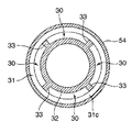
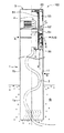
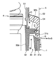
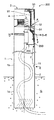
図1は、本発明の第1実施形態による植込み灯の全体構成を示した分解斜視図であり、図2は、第1実施形態の植込み灯を設置した状態を示した部分断面正面図である。また、図3は、図2中のIII−III線に沿った断面図であり、図4は、図2に示した植込み灯のスリット近傍の構成を示した拡大断面図である。また、図5および図6は、第1実施形態の植込み灯における風の流路、空気の流路および雨水の流路を示した断面正面図である。まず、図1および図2を参照して、第1実施形態の植込み灯100の全体構成について説明する。
(First embodiment)
FIG. 1 is an exploded perspective view showing an overall configuration of an implantable lamp according to a first embodiment of the present invention, and FIG. 2 is a partial sectional front view showing a state in which the implantable lamp of the first embodiment is installed. . 3 is a cross-sectional view taken along the line III-III in FIG. 2, and FIG. 4 is an enlarged cross-sectional view showing a configuration in the vicinity of the slit of the implanted lamp shown in FIG. 5 and 6 are cross-sectional front views showing the wind flow path, the air flow path, and the rainwater flow path in the implantable lamp of the first embodiment. First, with reference to FIG. 1 and FIG. 2, the whole structure of the
第1実施形態の植込み灯100は、駐車場の植込みや庭等の地面に立設され、その状態で周囲を照らすように構成されている。
The
この植込み灯100は、図1および図2に示すように、支柱として機能するパイプ1と、地中G(図2参照)に埋設され、パイプ1下端の開口を通してパイプ1内に引き込まれる配線2と、パイプ1内の上部に配設される器具本体3と、器具本体3に支持され、配線2の引き込み側の端部に電気的に接続されるランプユニット4と、器具本体3と共にランプユニット4を覆うように器具本体3に取付けられるカバーユニット5とを備えている。
As shown in FIGS. 1 and 2, the
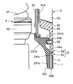
そして、本実施形態の植込み灯100では、カバーユニット5の後述する下端縁54aがパイプ1の上端縁1cに突き合っており、このパイプ1とカバーユニット5との突合せ部分には、略全周に亘って延びるスリットS(図2参照)が形成されている。すなわち、パイプ1の上端縁1cとカバーユニット5の下端縁54aとの間に所定隙間(前記スリットS)が形成されるように、カバーユニット5が器具本体3に取付けられている。このように、植込み灯100に略全周に亘って延びるスリットSを設けることによって、いずれの方向から吹く風も、スリットSの風上に対応する部分から風下に対応する部分へとスリットS内を滑らかに吹き抜けるようになる。なお、設置状態での植込み灯100の地上高さは、約80cm程度である。
In the
以下、植込み灯100の各構成要素について詳細に説明する。
Hereinafter, each component of the
パイプ1は、中空構造であり、当該パイプ1の下部を地中Gに埋め込むことで植込み灯100が地面に立設されるようになっている。このパイプ1は、地中Gに埋没する埋没部1aと、この埋没部1aの上方に位置し、地上に露出する露出部1bとにより構成されている。なお、本実施形態では、埋没部1aの長さが約40cm程度となっている。
The
露出部1bには、通気孔11が設けられている。この通気孔11は、図2に示すように、露出部1bの下部の地面からある程度離れた位置に設けられるのが好ましい。このような位置に設ければ、地面近くの湿気等が通気孔11からパイプ1内に入り込むのを抑えることができる。
A
露出部1bの上部には、同じ高さ位置でかつパイプ1の周方向に等角度間隔となるように3つのネジ挿入孔12が設けられている。このネジ挿入孔12には、パイプ1に器具本体3を固定するためのネジ61が各々挿入されるようになっている。
Three screw insertion holes 12 are provided in the upper part of the exposed
配線2は、器具本体3の後述の孔34aに挿通されるとともにランプユニット4に電気的に接続されており、これによって当該ランプユニット4に電力を供給するように構成されている。
The
器具本体3は、パイプ1に上方から挿入され、その挿入状態でパイプ1の上部にネジ61により固定されている。この器具本体3は、外筒部31と、内筒部32と、連結部33と、支持板34とを含んでいる。
The
外筒部31は、パイプ1に内嵌めされるように構成されている。この外筒部31は、外筒本体31aと、外筒フランジ31bと、逆流防止部31cとを有している。
The
外筒本体31aには、ネジ孔31dが形成されている。ネジ孔31dは、パイプ1のネジ挿入孔12に挿入したネジ61が螺合されるためのものであり、パイプ1のネジ挿入孔12に対応するように周方向に等角度間隔で3つ(図1では2つのみ図示)設けられている。
A
外筒フランジ31bは、図4に示すように、外筒本体31aの上部からスリットSに入り込むように径外方向に延在している。この外筒フランジ31bの上面は、カバーユニット5の下端縁54aとの間に所定の隙間を有しており、外筒フランジ31bの下面は、パイプ1の上端縁1cに上方から接触している。すなわち、本実施形態では、外筒フランジ31bの上面とカバーユニット5の下端縁54aとの隙間が、実質的なスリットSとして機能するようになっている。
As shown in FIG. 4, the
逆流防止部31cは、外筒本体31aの上端に形成されており、その上面が径外方向に向けて下るように傾斜している。これにより、雨水等が外筒部31を内周側に乗り越えるのを抑制可能となっている。
The
内筒部32は、外筒部31と同心で当該外筒部31の内周側に所定間隔を隔てて配設されている。この内筒部32には、カバーユニット5が取付けられている。また、内筒部32は、内筒本体32aと、内筒フランジ32bと、位置決め部32cとを含んでいる。
The
内筒本体32aは、後述するグローブ51の下端を支持するようになっている。内筒フランジ32bは、内筒本体32aの上端部から径外方向に延在しており、その外端縁が後述のカバー52の内周面と所定間隔を隔てて対向している。この内筒フランジ32bとカバー52との隙間を、雨水等が通過するようになっている。また、内筒フランジ32bは、逆流防止部31cに径方向でオーバーラップしており、これによって上記隙間を通過した雨水が逆流防止部31c上に落下するようになっている。
The inner cylinder
位置決め部32cは、内筒本体32aの上端部から上方に筒状に延設されており、内筒本体32aにより支持されるグローブ51の下端に内周側から接触することで、当該グローブ51を内筒本体32aと同心となるように位置決めするものである。
The
連結部33は、外筒部31および内筒部32を径方向に連結するためのものである。この連結部33は、図3に示すように、外筒部31と内筒部32との間に周方向に等角度間隔となるように4つ設けられている。
The
上記のように構成された器具本体3は、外筒部31と内筒部32と連結部33とにより囲まれる4つの通路30を有している。各通路30は、上下方向に延びており、その上端がスリットSに繋がるとともにその下端がパイプ1内の空間に繋がっている。本実施形態では、これら4つの通路30によって、スリットSと通気孔11とが連通している。
The instrument
支持板34は、内筒部32下端の開口を塞ぐように設けられており、ランプユニット4を内筒部32内に収容した状態で支持するものである。この支持板34の略中央には、配線2を通過させるための孔34aが形成されている。また、孔34aの直上位置には、パッキン36が配されており、配線2を支持板34の孔34aに水密状態で挿通することが可能なようになっている。
The
ランプユニット4は、光源としてのランプ41と、このランプ41を支持するソケット42とを有している。そして、ランプユニット4は、ランプ41がパイプ1の上端縁1cよりも上方に突出する姿勢で器具本体3に支持されている。ソケット42には、配線2が電気的に接続されている。
The
カバーユニット5は、ランプユニット4に覆い被さるように器具本体3に取付けられており、当該取付け状態でパイプ1の上端縁1cに突き合う下端縁54aを有している。このカバーユニット5は、グローブ51と、カバー52と、蓋53とを含んでいる。
The
グローブ51は、ランプユニット4を囲む筒状に形成されており、パッキン35を介して内筒本体32aに支持されている。また、グローブ51は、その外面に透過光を拡散させて和らげるためのプリズム部51aを有している。
The
カバー52は、固定部54と、一対の支柱55と、天板56とを有している。固定部54は、グローブ51の下部を取り囲むように当該グローブ51の外周との間に僅かな隙間を有する状態で配設されている。この隙間は、雨水等を通過させるために設けられている。また、固定部54には、周方向に等角度間隔となるように3つ(図1では2つのみ図示)のネジ孔54bが形成されている。各ネジ孔54bには、ネジ62が螺合されるようになっている。ネジ62は、図4に示すように、螺合状態でその先端が固定部54の内面側に突出するとともに、その突出先端が内筒フランジ32bの下面に下方から接触するように構成されており、これによってカバーユニット5が上抜けすることなく器具本体3に固定されている。
The
支柱55は、固定部54の上面の対称位置から上方に各々延設されており、それらの上端部で天板56を支持している。また、天板56は、ランプユニット4の上方に配されている。この天板56の下面には、パッキン57を介してグローブ51の上端が突き当たっている。このように、グローブ51の上下に設けられたパッキン35,57によって、ランプユニット4を含む空間の水密性が十分に確保されている。
The
蓋53は、下面開口の筒状(キャップ状)を呈しており、カバー52に上方から被さる姿勢で天板56にネジ63により固定されている。
The
このように構成された植込み灯100では、地中Gの湿気(図2の二点鎖線参照)がパイプ1内に籠もりやすくなっている。そして、パイプ1の頂部に設けたランプユニット4の収容空間に湿気が入り込んだ場合、ランプユニット4を覆っているカバーユニット5の内面に結露が発生する。
In the
しかし、本実施形態によれば、風が吹けば、当該風がスリットSを吹き抜けるので(図5および図6の矢印A参照)、パイプ1内の気圧が低下する。これにより、通気孔11から空気が流入し、この流入した空気はパイプ1内のより気圧の低い方向(上方)に向けて移動する(矢印B参照)。このとき、パイプ1内の湿気も空気と共に上方に移動する。そして、これらの空気および湿気は、スリットSを吹き抜ける風とともにスリットSから外部に流出する(矢印A+B参照)。このようにして、上記したような結露の発生を防ぐことができる。
However, according to the present embodiment, when the wind blows, the wind blows through the slit S (see arrow A in FIGS. 5 and 6), so the atmospheric pressure in the
また、上記構成の植込み灯100によれば、グローブ51に向けて斜め上方から降り込んだ雨水(図5および図6の矢印C参照)は、グローブ51とカバー54との隙間を通って内筒フランジ32bの上面に流れ落ち、さらに、内筒フランジ32bとカバー54との隙間を通って逆流防止部31cの上面に流れ落ちる。そして、スリットSを通って外部に排水される。
Further, according to the implanted
第1実施形態では、上記のように、パイプ1とカバーユニット5との突合せ部分に略全周に亘って延びるスリットSを形成することによって、いずれの方向から吹く風も、スリットSの風上に対応する部分から風下に対応する部分へとスリットS内を滑らかに吹き抜けることになる。すなわち、風がどの方向から吹いても、その風速が等しければ、スリットSを吹き抜ける風の速度はほぼ等速となる。さらに、器具本体3にスリットSと通気孔11とを連通させる通路30を設けることによって、風がスリットSを吹き抜けることによって通路30を介してパイプ1内が減圧され(負圧になり)、通気孔11からパイプ1内に空気が流入し、この流入した空気が通路30を通ってスリットSを吹き抜ける風と共に外部に流出するようになるため、通気孔11を入口としスリットSを出口とするパイプ1内を通り抜ける気流が自然に発生する。そして、当該気流によってパイプ1内の湿気がスリットSから外部に排出されるようになる。ここで、上述したように、風向きにかかわらず、スリットSを吹き抜ける風の速度がほぼ一定であるので、風向きが変わってもパイプ1内の気圧(負圧)が変化しにくい。これにより、パイプ1内を通り抜ける気流の速度が変化しにくくなるので、パイプ1内の湿気の排出効率が大きく低下することがなくなる。従って、ランプユニット4の収容空間内に湿気が入り込むのを継続して抑えることができるので、グローブ51の内面に結露が発生しにくくなり、結露による見栄えの悪化や放射光量の低下を防ぐことができる。
In the first embodiment, as described above, the slit S extending substantially over the entire circumference is formed in the abutting portion between the
また、スリットSと通気孔11とを連通させる通路30を器具本体3に設けたので、通気孔11を入口としスリットSを出口とする気流が器具本体3近傍に配されることになる。これにより、器具本体3付近に湿気が滞留するのを確実に防ぐことができるので、ランプユニット4の収容空間内に湿気が入り込むのをさらに抑えることができる。
In addition, since the
また、第1実施形態の植込み灯100によれば、グローブ51とカバー52との隙間を伝い落ちる雨水を、内筒フランジ32bで受けた後、内筒フランジ32bとカバー52との隙間を通して逆流防止部31cの上面に誘導し、当該逆流防止部31cおよび外筒フランジ31bの上面からスリットSを通して外部に排水することができる。
Moreover, according to the
また、第1実施形態では、上記のように、スリットSと通気孔11とが高さ方向にある程度離れて配置されているため、通気孔11を入口としスリットSを出口とする気流の速度がいわゆるトンネル効果によって早くなっている。これにより、パイプ1内の湿気の排出効率が向上している。
Further, in the first embodiment, as described above, the slit S and the
(第2実施形態)
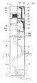
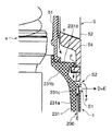
図7は、本発明の第2実施形態による植込み灯を設置した状態を示した部分断面正面図であり、図8は、図5に示した植込み灯のスリット近傍の構成を示した拡大断面図である。また、図9および図10は、第2実施形態の植込み灯における風の流路、空気の流路および雨水の流路を示した断面正面図である。
(Second Embodiment)
FIG. 7 is a partial cross-sectional front view showing a state where an implantable lamp according to a second embodiment of the present invention is installed, and FIG. 8 is an enlarged cross-sectional view showing a configuration in the vicinity of the slit of the implantable lamp shown in FIG. It is. FIG. 9 and FIG. 10 are cross-sectional front views showing a wind flow path, an air flow path, and a rainwater flow path in the implantable lamp of the second embodiment.
この第2実施形態の植込み灯200は、第1実施形態の器具本体3とは異なる構成の器具本体203を備えており、これに伴ってスリットS´および通路230の構成も第1実施形態とは異なっている。
The
具体的には、第2実施形態の器具本体203は、パイプ1に完全に嵌まり込むことなく上方に僅かに浮いた状態でパイプ1に取付けられている。この器具本体203は、図7および図8に示すように、筒部231と、第1実施形態と同様の構成の支持板34とにより構成されている。
Specifically, the instrument
筒部231は、パイプ1の内周側に所定間隔を隔てた状態で当該パイプ1に取付けられる下筒体231aと、この下筒体231aの上端部から縮径しながら上方に延びてグローブ51の下端を支持する上筒体231bと、下筒体231aおよび上筒体231bの境界部分からスリットS´に入り込むように径外方向に延びてパイプ1の上端縁1cおよびカバーユニット5の下端縁54aの両方に非接触となる下側フランジ231cと、上筒体231bの上端部から径外方向に延び、その外端縁がカバー52の内周面と所定間隔を隔てて対向する上側フランジ231dとを有している。
The
そして、本実施形態の植込み灯200では、パイプ1とカバーユニット5との突合せ部分に略全周に亘って延びるスリットS´が形成されており、このスリットS´は、図8に示すように、下側フランジ231cによって下側スリットS1と上側スリットS2とに分けられている。
And in the
また、器具本体203は、下筒体231aとパイプ1とにより囲まれる通路230を有している。この通路230は、上下方向に延びており、その上端が下側スリットS1に繋がるとともにその下端がパイプ1内の空間に繋がっている。本実施形態では、この通路230によって、下側スリットS1と通気孔11とが連通している。
The instrument
この第2実施形態の植込み灯200によれば、風が吹けば、当該風が下側スリットS1を吹き抜けるので(図9および図10の矢印D参照)、パイプ1内の気圧が低下する。これにより、通気孔11から空気が流入し、この流入した空気はパイプ1内のより気圧の低い方向(上方)に向けて移動する(矢印E参照)。このとき、パイプ1内の湿気も空気と共に上方に移動する。そして、これらの空気および湿気は、下側スリットS1を吹き抜ける風とともに下側スリットS1から外部に流出する(矢印D+E参照)。このようにして、カバーユニット5の内面に結露が発生するのを防ぐことができる。
According to the
また、上記構成の植込み灯200によれば、グローブ51に向けて斜め上方から降り込んだ雨水(図9および図10の矢印F参照)は、グローブ51とカバー54との隙間を通って上側フランジ231dの上面に流れ落ち、さらに、上側フランジ231dとカバー54との隙間を通って下側フランジ231cの上面に流れ落ちる。そして、上側スリットS2を通って外部に排水される。
Further, according to the
第2実施形態の植込み灯200によれば、グローブ51とカバー1との隙間を伝い落ちる雨水を、下側フランジ231cの上面から上側スリットS2を通して外部に排水することができる。また、パイプ1内の湿気を含んだ空気を、通路230および下側スリットS1を通して外部に排出することができる。
According to the
また、第2実施形態の植込み灯200では、器具本体203を上方に浮かせた状態でパイプ1に固定することによって、容易に通路230を形成することが可能となっている。
Moreover, in the
なお、今回開示された実施形態は、すべての点で例示であって制限的なものではないと考えられるべきである。本発明の範囲は、上記した実施形態の説明ではなく特許請求の範囲によって示され、さらに特許請求の範囲と均等の意味および範囲内でのすべての変更が含まれる。 The embodiment disclosed this time should be considered as illustrative in all points and not restrictive. The scope of the present invention is shown not by the above description of the embodiments but by the scope of claims for patent, and further includes all modifications within the meaning and scope equivalent to the scope of claims for patent.
例えば、第1実施形態の器具本体3を、第2実施形態の器具本体203のように、上方に浮かした態様でパイプ1に取付ける構成であってもよい。この場合、スリットSと通気孔11とを連通させる通路が、外筒部31の径方向外側と内側とに各々形成されることになる。
For example, the structure which attaches the instrument
また、上記実施形態では、パイプに設ける通気孔の数は、当該植込み灯の外観が著しく悪化しない範囲であれば制限するものではない。 Moreover, in the said embodiment, the number of the vent holes provided in a pipe will not be restrict | limited if it is a range in which the external appearance of the said implantation lamp does not deteriorate remarkably.
また、上記実施形態では、地面に直接埋め込まれた植込み灯に本発明を適用する例について示したが、これに限らず、コンクリート基礎を介して地面に立設される植込み灯にも本発明を適用可能である。なお、コンクリート基礎は一般に完全に乾燥するのに長い年月を要するものであり、それまでは、コンクリートから水分が蒸発し続けるため、植込み灯を地面に直接埋め込む場合と同様、植込み灯のパイプ内に多量の湿気が籠もりやすくなっている。従って、本発明を適用することによって、十分な効果が得られるものである。 Moreover, in the said embodiment, although the example which applies this invention to the implantation lamp directly embedded in the ground was shown, not only this but this invention is applied also to the implantation lamp standing on the ground via a concrete foundation. Applicable. In addition, concrete foundations generally take a long time to completely dry, and until then, moisture will continue to evaporate from the concrete. A large amount of moisture is easily trapped. Therefore, a sufficient effect can be obtained by applying the present invention.
1 パイプ
1a 埋没部
1c 上端縁
3,203 器具本体
4 ランプユニット
5 カバーユニット
11 通気孔
30,230 通路
31 外筒部
31a 外筒本体
31b 外筒フランジ
32 内筒部
32a 内筒本体
32b 内筒フランジ
33 連結部
51 グローブ
52 カバー
54a 下端縁
100,200 植込み灯
231 筒部
231a 下筒体
231b 上筒体
231c 下側フランジ(フランジ)
S,S´ スリット
S1 下側スリット
S2 上側スリット
DESCRIPTION OF
S, S 'slit S1 lower slit S2 upper slit
Claims (5)
このパイプ内の上部に配設され、ランプユニットを支持する器具本体と、
前記ランプユニットを前記器具本体と共に覆うように器具本体に取付けられ、当該取付け状態で前記パイプの上端縁に突き合う下端縁を有するカバーユニットとを備えた植込み灯であって、
前記パイプと前記カバーユニットとの突合せ部分には、略全周に亘って延びるスリットが形成されており、
前記器具本体には、前記スリットと前記通気孔とを連通させる通路が設けられていることを特徴とする植込み灯。 A pipe having a buried portion buried in the ground and a vent hole provided above the buried portion;
An instrument body that is disposed in the upper part of the pipe and supports the lamp unit;
An implantable lamp comprising: a cover unit that is attached to the instrument body so as to cover the lamp unit together with the instrument body, and has a lower end edge that abuts the upper end edge of the pipe in the attached state;
In the butt portion between the pipe and the cover unit, a slit is formed that extends over substantially the entire circumference.
An implantable lamp characterized in that a passage for communicating the slit and the vent hole is provided in the instrument body.
前記外筒部、前記内筒部および前記連結部により囲まれる空間部が、前記通路として機能することを特徴とする請求項1に記載の植込み灯。 The instrument main body is disposed on the inner cylinder side of the outer cylinder part concentrically with the outer cylinder part fitted inside the pipe, with a predetermined interval and supports the lamp unit. An inner cylinder portion to which a cover unit is attached; and a connecting portion that connects the outer cylinder portion and the inner cylinder portion;
The implantable lamp according to claim 1, wherein a space portion surrounded by the outer tube portion, the inner tube portion, and the connecting portion functions as the passage.
前記外筒部は、前記パイプに取付けられる外筒本体と、この外筒本体の上部から前記スリットに入り込むように径外方向に延びて前記パイプの上端縁に上方から接触する外筒フランジとを有し、
前記内筒部は、前記グローブの下端を支持する内筒本体と、この内筒本体の上端部から径外方向に延び、その外端縁が前記カバーの内周面と所定間隔を隔てて対向する内筒フランジとを有し、
前記内筒フランジは、前記外筒本体に径方向でオーバーラップしており、
前記外筒本体の上面は、外方に向かって下るように傾斜していることを特徴とする請求項2に記載の植込み灯。 The cover unit includes a glove surrounding the lamp unit, and a cover disposed on the outer peripheral side of the glove,
The outer cylinder portion includes an outer cylinder main body attached to the pipe, and an outer cylinder flange that extends radially outward so as to enter the slit from the upper portion of the outer cylinder main body and contacts the upper end edge of the pipe from above. Have
The inner cylinder portion extends radially outwardly from an inner cylinder main body that supports the lower end of the globe, and an outer edge thereof faces the inner peripheral surface of the cover with a predetermined interval. An inner cylinder flange that
The inner cylinder flange overlaps the outer cylinder body in the radial direction,
The implantable lamp according to claim 2, wherein an upper surface of the outer cylinder main body is inclined so as to descend downward.
この筒部と前記パイプとにより囲まれる空間部が、前記通路として機能することを特徴とする請求項1に記載の植込み灯。 The instrument body includes a cylinder portion attached to the pipe in a state of being spaced a predetermined distance on the inner peripheral side of the pipe,
The implantable lamp according to claim 1, wherein a space portion surrounded by the cylindrical portion and the pipe functions as the passage.
前記筒部は、前記パイプに取付けられる下筒体と、この下筒体の上端部から縮径しながら上方に延びて前記グローブの下端を支持する上筒体と、前記下筒体と前記上筒体との境界部分から前記スリットに入り込むように径外方向に延びて前記パイプの上端縁および前記カバーユニットの下端縁の両方に非接触となるフランジとを有し、
前記スリットは、前記フランジによって上側スリットと下側スリットとに分けられ、前記下側スリットが前記通路に連通していることを特徴とする請求項4に記載の植込み灯。 The cover unit includes a globe that surrounds the lamp unit, and a cover that is disposed on an outer peripheral side of the globe,
The cylindrical portion includes a lower cylindrical body attached to the pipe, an upper cylindrical body that extends upward from the upper end portion of the lower cylindrical body and supports the lower end of the globe, the lower cylindrical body, and the upper cylindrical body. A flange that extends in a radially outward direction so as to enter the slit from a boundary portion with a cylindrical body and has a non-contact flange on both the upper end edge of the pipe and the lower end edge of the cover unit;
5. The implantable lamp according to claim 4, wherein the slit is divided into an upper slit and a lower slit by the flange, and the lower slit communicates with the passage.
Priority Applications (1)
| Application Number | Priority Date | Filing Date | Title |
|---|---|---|---|
| JP2007172509A JP2009009902A (en) | 2007-06-29 | 2007-06-29 | Light |
Applications Claiming Priority (1)
| Application Number | Priority Date | Filing Date | Title |
|---|---|---|---|
| JP2007172509A JP2009009902A (en) | 2007-06-29 | 2007-06-29 | Light |
Publications (1)
| Publication Number | Publication Date |
|---|---|
| JP2009009902A true JP2009009902A (en) | 2009-01-15 |
Family
ID=40324768
Family Applications (1)
| Application Number | Title | Priority Date | Filing Date |
|---|---|---|---|
| JP2007172509A Pending JP2009009902A (en) | 2007-06-29 | 2007-06-29 | Light |
Country Status (1)
| Country | Link |
|---|---|
| JP (1) | JP2009009902A (en) |
Cited By (2)
| Publication number | Priority date | Publication date | Assignee | Title |
|---|---|---|---|---|
| JP2011222282A (en) * | 2010-04-09 | 2011-11-04 | Sankyo Tateyama Aluminium Inc | Illumination device |
| JP2024051431A (en) * | 2022-09-30 | 2024-04-11 | Ykk Ap株式会社 | Lighting equipment |
-
2007
- 2007-06-29 JP JP2007172509A patent/JP2009009902A/en active Pending
Cited By (2)
| Publication number | Priority date | Publication date | Assignee | Title |
|---|---|---|---|---|
| JP2011222282A (en) * | 2010-04-09 | 2011-11-04 | Sankyo Tateyama Aluminium Inc | Illumination device |
| JP2024051431A (en) * | 2022-09-30 | 2024-04-11 | Ykk Ap株式会社 | Lighting equipment |
Similar Documents
| Publication | Publication Date | Title |
|---|---|---|
| KR100959937B1 (en) | Water-proof reinforced dome type security camera structure | |
| JP6072847B2 (en) | Installation fixture | |
| JP2009009902A (en) | Light | |
| RU2589676C2 (en) | Device for exhaust ventilation pipe | |
| KR100479390B1 (en) | ventilator | |
| US20060199527A1 (en) | Attic vent | |
| TW201641899A (en) | Air-exchanging device and separating member thereof | |
| KR20240029368A (en) | Sleeve connector for ventilation | |
| JP2004111284A (en) | Rainproof lighting equipment | |
| JP5023933B2 (en) | Outdoor lighting equipment | |
| JP3806153B2 (en) | lighting equipment | |
| TWI650486B (en) | ceiling fan | |
| JP4640182B2 (en) | Lighting pole | |
| JP5285232B2 (en) | Drainage piping structure | |
| CN206398195U (en) | Pipeline discharge structure | |
| JP3500818B2 (en) | lighting equipment | |
| JP3110711U (en) | Vent cap for ventilation | |
| CN103956662B (en) | A kind of power system outdoor use casing | |
| JP2002364115A (en) | Roof ventilation structure | |
| JPH0522727Y2 (en) | ||
| CN220674109U (en) | Beidou time service safety isolation protection device | |
| KR20190071948A (en) | Dome camera | |
| KR101212773B1 (en) | Ventilator for urethane waterproofing layer | |
| GB2431959A (en) | Building illumination with roof structure and diffuser | |
| JPH0537821Y2 (en) |