JP2009144792A - Bearing device for wheel - Google Patents
Bearing device for wheel Download PDFInfo
- Publication number
- JP2009144792A JP2009144792A JP2007321545A JP2007321545A JP2009144792A JP 2009144792 A JP2009144792 A JP 2009144792A JP 2007321545 A JP2007321545 A JP 2007321545A JP 2007321545 A JP2007321545 A JP 2007321545A JP 2009144792 A JP2009144792 A JP 2009144792A
- Authority
- JP
- Japan
- Prior art keywords
- seal
- wheel
- bearing device
- wheel bearing
- lip
- Prior art date
- Legal status (The legal status is an assumption and is not a legal conclusion. Google has not performed a legal analysis and makes no representation as to the accuracy of the status listed.)
- Pending
Links
- 239000002184 metal Substances 0.000 claims abstract description 38
- 229910052751 metal Inorganic materials 0.000 claims abstract description 38
- 238000005096 rolling process Methods 0.000 claims description 44
- 239000000725 suspension Substances 0.000 claims description 4
- 238000007789 sealing Methods 0.000 description 21
- 239000010960 cold rolled steel Substances 0.000 description 9
- 230000004048 modification Effects 0.000 description 7
- 238000012986 modification Methods 0.000 description 7
- 229910000963 austenitic stainless steel Inorganic materials 0.000 description 6
- XLYOFNOQVPJJNP-UHFFFAOYSA-N water Substances O XLYOFNOQVPJJNP-UHFFFAOYSA-N 0.000 description 6
- 239000000428 dust Substances 0.000 description 4
- 238000003825 pressing Methods 0.000 description 4
- OKTJSMMVPCPJKN-UHFFFAOYSA-N Carbon Chemical compound [C] OKTJSMMVPCPJKN-UHFFFAOYSA-N 0.000 description 3
- 241000221535 Pucciniales Species 0.000 description 3
- 229910052799 carbon Inorganic materials 0.000 description 3
- 238000000034 method Methods 0.000 description 3
- 229910000677 High-carbon steel Inorganic materials 0.000 description 2
- 229910000954 Medium-carbon steel Inorganic materials 0.000 description 2
- -1 S53C Chemical compound 0.000 description 2
- 230000005540 biological transmission Effects 0.000 description 2
- PCHJSUWPFVWCPO-UHFFFAOYSA-N gold Chemical compound [Au] PCHJSUWPFVWCPO-UHFFFAOYSA-N 0.000 description 2
- 239000010931 gold Substances 0.000 description 2
- 229910052737 gold Inorganic materials 0.000 description 2
- 239000004519 grease Substances 0.000 description 2
- 230000006698 induction Effects 0.000 description 2
- 102220097517 rs876659265 Human genes 0.000 description 2
- 229910000669 Chrome steel Inorganic materials 0.000 description 1
- 229910000831 Steel Inorganic materials 0.000 description 1
- 238000005452 bending Methods 0.000 description 1
- 230000037396 body weight Effects 0.000 description 1
- 230000001747 exhibiting effect Effects 0.000 description 1
- 239000000446 fuel Substances 0.000 description 1
- 238000012856 packing Methods 0.000 description 1
- 230000002093 peripheral effect Effects 0.000 description 1
- 238000010791 quenching Methods 0.000 description 1
- 230000000171 quenching effect Effects 0.000 description 1
- 239000010959 steel Substances 0.000 description 1
Images

Landscapes
- Rolling Contact Bearings (AREA)
Abstract
Description
本発明は、自動車等の車輪を回転自在に支承する車輪用軸受装置、特に、密封性能の向上を図った車輪用軸受装置に関するものである。 The present invention relates to a wheel bearing device for rotatably supporting a wheel of an automobile or the like, and more particularly to a wheel bearing device with improved sealing performance.
従来から自動車等の車輪を支持する車輪用軸受装置は、車輪を取り付けるためのハブ輪を転がり軸受を介して回転自在に支承するもので、駆動輪用と従動輪用とがある。構造上の理由から、駆動輪用では内輪回転方式が、従動輪用では内輪回転と外輪回転の両方式が一般的に採用されている。この車輪用軸受装置には、所望の軸受剛性を有し、ミスアライメントに対しても耐久性を発揮すると共に、燃費向上の観点から回転トルクが小さい複列アンギュラ玉軸受が多用されている。一方、オフロードカーやトラック等、車体重量が嵩む車両には複列円錐ころ軸受が使用されている。 2. Description of the Related Art Conventionally, a wheel bearing device for supporting a wheel of an automobile or the like is such that a hub wheel for mounting a wheel is rotatably supported via a rolling bearing, and there are a drive wheel and a driven wheel. For structural reasons, an inner ring rotation method is generally used for driving wheels, and an inner ring rotation method and an outer ring rotation method are generally used for driven wheels. As the wheel bearing device, a double-row angular ball bearing having a desired bearing rigidity, exhibiting durability against misalignment, and having a small rotational torque from the viewpoint of improving fuel efficiency is often used. On the other hand, double row tapered roller bearings are used in vehicles such as off-road cars and trucks that have a heavy vehicle body weight.
これらの車輪用軸受装置は、泥水等がかかり易い部位に配置されるため、シール装置が装着され、外方部材と内方部材との間を密封するように構成されている。一般的に、シール装置は、シールリップを備えたシール部材が固定側部材となる外方部材に装着され、シールリップが内方部材の外周面に摺接されている。特に、オフロードカーやピックアップトラック等のように、劣悪な環境で運転される車両においては、密封性をさらに向上させるための手段が種々講じられている。 Since these wheel bearing devices are arranged at sites where muddy water or the like is likely to be applied, a seal device is mounted, and the space between the outer member and the inner member is sealed. Generally, in a sealing device, a sealing member having a sealing lip is attached to an outer member serving as a stationary member, and the sealing lip is slidably contacted with an outer peripheral surface of the inner member. In particular, in a vehicle that is driven in a poor environment such as an off-road car or a pickup truck, various means for further improving the sealing performance are taken.
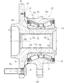
こうした密封性を向上させた車輪用軸受装置を本出願人は提案している。この車輪用軸受装置は、図8に示すように、ハブ輪51と車輪用軸受52とからなり、車輪用軸受52は、外方部材53と、複列の円錐ころ54、54を介して内嵌された一対の内輪55、55とを備えている。
The present applicant has proposed such a wheel bearing device with improved sealing performance. As shown in FIG. 8, the wheel bearing device includes a
ハブ輪51は、一端部に車輪(図示せず)を取り付けるための車輪取付フランジ56を一体に有し、この車輪取付フランジ56から軸方向に延びる小径段部51aが形成され、内周にトルク伝達用のセレーション(またはスプライン)51bが形成されている。車輪取付フランジ56にはハブボルト56aが周方向等配に植設されている。
The
車輪用軸受52は、ハブ輪51の小径段部51aに所定のシメシロを介して圧入され、小径段部51aの端部を径方向外方に塑性変形させて形成した加締部51cによってハブ輪51に対して軸方向に固定されている。
The wheel bearing 52 is press-fitted into the small-
車輪用軸受52の外方部材53は、外周にナックル(図示せず)に取り付けられるための車体取付フランジ53bを一体に有し、内周にそれぞれ外向きに開いたテーパ状の複列の外側転走面53a、53aが一体に形成されている。
The
一方、内輪55の外周には、前記複列の外側転走面53a、53aに対向するテーパ状の内側転走面55aと、この内側転走面55aの大径側に円錐ころ54を案内する大鍔55b、および小径側に円錐ころ54の脱落を防止するための小鍔55cがそれぞれ形成されている。そして、外方部材53と一対の内輪55、55の両転走面間に複列の円錐ころ54、54が収容され、保持器57、57によって転動自在に保持されている。また、外方部材53と内輪55との間に形成される環状空間の開口部にはシール58、58が装着されている。これらのシール58、58によって、軸受内部に封入されたグリースの外部への漏洩と、外部から雨水やダスト等が軸受内部に侵入するのを防止している。
On the other hand, on the outer periphery of the
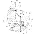
シール58は、図9に拡大して示すように、断面が略L字状をなして互いに対向配置された環状のシール板59とスリンガ60とからなる、所謂パックシールを構成している。シール板59は、断面が略L字状に形成され、外方部材53の端部内周に圧入された芯金61と、この芯金61に一体に加硫接着されたシール部材62とからなる。
As shown in an enlarged view in FIG. 9, the
一方、スリンガ60は断面が略L字状に形成され、内輪55の大鍔55bに圧入される円筒部60aと、この円筒部60aから径方向外方に延びる立板部60bとからなる。そして、シール部材62に一体に形成された一対のサイドリップ62a、62bがこのスリンガ60の立板部60bに摺接すると共に、円筒部60aにはラジアルリップ62cが摺接している。
On the other hand, the
さらに、外方部材53の端部外周にバックアップシール63が圧入されている。このバックアップシール63は、断面が略L字状に形成された芯金64と、この芯金64に一体に加硫接着されたシール部材65とからなる。一方、シール部材65は、芯金64の外縁に固着された基部65aと、この基部65aから径方向外方に傾斜して延び、先端部が拡径するラッパ状に形成されたサイドリップ65bとからなる。
Further, a
このサイドリップ65bは、車輪取付フランジ56のインナー側の側面56cに固定ボルト67によって固定された金属環66に摺接され、雨水やダスト等が前記シール58に直接侵入するのを防止している。したがって、ハブ輪51と車輪用軸受52との間の狭い環状空間に泥水等が滞留し、車輪取付フランジ56の基部56bが発錆して耐久強度が低下するのを抑制することができる。
然しながら、こうした従来の車輪用軸受装置では、車輪取付フランジ56と外方部材53の端部とが近接した構造の場合、バックアップシール63のスペースを充分に確保することが難しくなり、サイドリップ65bの長さを短くせざるを得ない。これでは、適切な接触圧を有する最適設計は難しく、また、リップ摩耗によってシメシロが変動して密封性が低下する恐れがあった。
However, in such a conventional wheel bearing device, when the
本発明は、このような事情に鑑みてなされたもので、シールの密封性能の向上を図り、軸受性能を長期間に亘って維持することができる車輪用軸受装置を提供することを目的としている。 This invention is made | formed in view of such a situation, and aims at the improvement of the sealing performance of a seal | sticker, and it aims at providing the wheel bearing apparatus which can maintain bearing performance over a long period of time. .
係る目的を達成すべく、本発明のうち請求項1記載の発明は、外周に懸架装置に取り付けられるための車体取付フランジを一体に有し、内周に複列の外側転走面が一体に形成された外方部材と、一端部に車輪を取り付けるための車輪取付フランジを一体に有し、外周に小径段部が形成されたハブ輪、およびこのハブ輪に嵌合された内輪または等速自在継手の外側継手部材からなり、外周に前記複列の外側転走面に対向する複列の内側転走面が形成された内方部材と、この内方部材と前記外方部材の両転走面間に保持器を介して転動自在に収容された複列の転動体と、前記外方部材と内方部材とで形成される環状空間の開口部に装着されたシールとを備えた車輪用軸受装置において、前記外方部材のアウター側の端部にバックアップシールが装着され、このバックアップシールが、前記外方部材の端部外周に圧入される円筒状の嵌合部を有する芯金と、この芯金に一体に加硫接着されたシール部材とからなると共に、当該シール部材が、径方向外方に傾斜して延び、先端部が拡径するラッパ状に形成されて前記車輪取付フランジのインナー側の側面に摺接されたサイドリップを有し、このサイドリップの基部が前記芯金のインナー側の端部に固着されている。 In order to achieve such an object, the invention according to claim 1 of the present invention has a vehicle body mounting flange integrally attached to the suspension on the outer periphery, and a double row outer rolling surface integrally on the inner periphery. A formed outer member and a hub wheel integrally having a wheel mounting flange for mounting a wheel at one end and a small-diameter stepped portion formed on the outer periphery, and an inner ring or a constant speed fitted to the hub ring An inner member comprising an outer joint member of a universal joint and having a double-row inner rolling surface facing the double-row outer rolling surface on the outer periphery, and both the inner member and the outer member. A double row rolling element accommodated between the running surfaces via a cage, and a seal attached to an opening of an annular space formed by the outer member and the inner member. In the wheel bearing device, a backup seal is mounted on the outer end of the outer member. The backup seal is composed of a core metal having a cylindrical fitting portion press-fitted into the outer periphery of the end portion of the outer member, and a seal member integrally vulcanized and bonded to the core metal. The seal member has a side lip that extends in a radially outward direction and has a side lip that is formed in a trumpet shape in which a tip end portion is enlarged and is in sliding contact with an inner side surface of the wheel mounting flange. The base is fixed to the inner side end of the cored bar.
このように、外方部材と内方部材とで形成される環状空間の開口部に装着されたシールを備えた車輪用軸受装置において、外方部材のアウター側の端部にバックアップシールが装着され、このバックアップシールが、外方部材の端部外周に圧入される円筒状の嵌合部を有する芯金と、この芯金に一体に加硫接着されたシール部材とからなると共に、当該シール部材が、径方向外方に傾斜して延び、先端部が拡径するラッパ状に形成されて車輪取付フランジのインナー側の側面に摺接されたサイドリップを有し、このサイドリップの基部が芯金のインナー側の端部に固着されているので、車輪取付フランジと外方部材の端部とが近接した構造であっても、シール部材のスペースを充分に確保することができ、サイドリップの適切な接触圧を有する最適設計ができる。すなわち、サイドリップに適切な剛性を持たせ、リップ摩耗によってシメシロが変動して密封性が低下するのを防止することができると共に、密封性能の向上を図り、軸受性能を長期間に亘って維持することができる車輪用軸受装置を提供することができる。 As described above, in the wheel bearing device including the seal mounted on the opening of the annular space formed by the outer member and the inner member, the backup seal is mounted on the outer end of the outer member. The backup seal is composed of a metal core having a cylindrical fitting portion that is press-fitted into the outer periphery of the end of the outer member, and a seal member that is integrally vulcanized and bonded to the metal core. However, it has a side lip formed in a trumpet shape that extends in a radially outward direction and has a tip that expands in diameter, and is in sliding contact with the side surface on the inner side of the wheel mounting flange. Since it is fixed to the end portion on the inner side of the gold, even if the wheel mounting flange and the end portion of the outer member are close to each other, a sufficient space for the seal member can be secured, and the side lip Have appropriate contact pressure It is the optimal design. In other words, the side lip has an appropriate rigidity to prevent the seal from changing due to lip wear, and to improve the sealing performance, maintaining the bearing performance over a long period of time. A wheel bearing device that can be provided can be provided.
好ましくは、請求項2に記載の発明のように、前記芯金が、前記嵌合部のインナー側の端部から径方向外方に折曲された凸部を有していれば、芯金の剛性が高くなり、バックアップシールの抜け耐力が増大して信頼性が向上すると共に、サイドリップの接触圧を維持することができ、長期間に亘って所望の密封性を確保することができる。 Preferably, as in the invention described in claim 2, if the cored bar has a convex part bent radially outward from the inner side end of the fitting part, the cored bar This increases the rigidity of the back-up seal and improves the reliability of the back-up seal, while maintaining the contact pressure of the side lip and ensuring the desired sealing performance over a long period of time.
また、請求項3に記載の発明のように、前記芯金が、前記嵌合部のアウター側の端部から径方向内方に延び、前記外方部材の端面に密着する鍔部を有していれば、芯金の剛性が一層高くなり、バックアップシールの抜け耐力が一層増大して信頼性が向上すると共に、シール圧入治具の当接面積が増大し、圧入性と位置決め精度が向上する。
Further, as in the invention described in
好ましくは、請求項4に記載の発明のように、前記シールのうちアウター側のシールが、断面が略L字状をなして互いに対向配置された環状のシール板とスリンガとからなると共に、前記芯金の鍔部の内径が前記スリンガの外径よりも小径に設定され、前記シールとの間にラビリンスシールが構成されていれば、バックアップシールから泥水等が浸入してもシールの密封性を向上させることができる。 Preferably, as in the invention according to claim 4, the seal on the outer side of the seals is composed of an annular seal plate and a slinger arranged in opposition to each other with a substantially L-shaped cross section. If the inner diameter of the collar portion of the metal core is set to be smaller than the outer diameter of the slinger and a labyrinth seal is formed between the seal and the seal, even if muddy water or the like enters from the backup seal, the sealing performance of the seal is improved. Can be improved.
また、請求項5に記載の発明のように、前記サイドリップの基部が前記芯金のインナー側の端部を覆うように固着されていれば、芯金の表面が外部に露出することがなく、高価なオーステナイト系ステンレス鋼鈑等から比較的廉価な冷間圧延鋼鈑に変更することができるため低コスト化を図ることができる。 Further, as in the fifth aspect of the invention, if the base portion of the side lip is fixed so as to cover the end portion on the inner side of the core metal, the surface of the core metal is not exposed to the outside. Further, since it can be changed from an expensive austenitic stainless steel plate to a relatively inexpensive cold rolled steel plate, the cost can be reduced.
また、請求項6に記載の発明のように、前記車輪取付フランジのインナー側の側面に密着して防錆能を有する金属環が装着され、この金属環に前記バックアップシールのサイドリップが摺接されていれば、ハブ輪と車輪用軸受との間の狭い環状空間に泥水等が滞留して車輪取付フランジの側面が発錆しても、リップ摺接面の発錆を防止することができ、長期間に亘ってリップ摩耗を防止して密封性を向上させることができる。
Further, as in the invention described in
本発明に係る車輪用軸受装置は、外周に懸架装置に取り付けられるための車体取付フランジを一体に有し、内周に複列の外側転走面が一体に形成された外方部材と、一端部に車輪を取り付けるための車輪取付フランジを一体に有し、外周に小径段部が形成されたハブ輪、およびこのハブ輪に嵌合された内輪または等速自在継手の外側継手部材からなり、外周に前記複列の外側転走面に対向する複列の内側転走面が形成された内方部材と、この内方部材と前記外方部材の両転走面間に保持器を介して転動自在に収容された複列の転動体と、前記外方部材と内方部材とで形成される環状空間の開口部に装着されたシールとを備えた車輪用軸受装置において、前記外方部材のアウター側の端部にバックアップシールが装着され、このバックアップシールが、前記外方部材の端部外周に圧入される円筒状の嵌合部を有する芯金と、この芯金に一体に加硫接着されたシール部材とからなると共に、当該シール部材が、径方向外方に傾斜して延び、先端部が拡径するラッパ状に形成されて前記車輪取付フランジのインナー側の側面に摺接されたサイドリップを有し、このサイドリップの基部が前記芯金のインナー側の端部に固着されているので、車輪取付フランジと外方部材の端部とが近接した構造であっても、シール部材のスペースを充分に確保することができ、サイドリップの適切な接触圧を有する最適設計ができる。すなわち、サイドリップに適切な剛性を持たせ、リップ摩耗によってシメシロが変動して密封性が低下するのを防止することができると共に、密封性能の向上を図り、軸受性能を長期間に亘って維持することができる車輪用軸受装置を提供することができる。 A wheel bearing device according to the present invention has an outer member integrally formed with a vehicle body mounting flange for mounting to a suspension device on the outer periphery, and an outer member formed integrally with a double row outer rolling surface on the inner periphery, and one end A hub ring integrally having a wheel mounting flange for mounting a wheel on the part, and a outer ring member of an inner ring or a constant velocity universal joint fitted to the hub ring, and a small-diameter stepped portion formed on the outer periphery, An inner member in which a double row inner rolling surface facing the outer rolling surface of the double row is formed on the outer periphery, and a cage is provided between both rolling surfaces of the inner member and the outer member. A wheel bearing device comprising: a double row of rolling elements housed so as to be freely rollable; and a seal attached to an opening of an annular space formed by the outer member and the inner member. A backup seal is attached to the outer end of the member. Is comprised of a cored bar having a cylindrical fitting portion that is press-fitted into the outer periphery of the end of the outer member, and a seal member that is integrally vulcanized and bonded to the cored bar. The side lip has a side lip that extends in a radially outward direction and is formed in a trumpet shape whose tip is enlarged in diameter, and is in sliding contact with the inner side surface of the wheel mounting flange. Since it is fixed to the end portion on the inner side of the gold, even if the wheel mounting flange and the end portion of the outer member are close to each other, a sufficient space for the seal member can be secured, and the side lip Optimal design with appropriate contact pressure is possible. In other words, the side lip has an appropriate rigidity to prevent the seal from changing due to lip wear, and to improve the sealing performance, maintaining the bearing performance over a long period of time. A wheel bearing device that can be provided can be provided.
一端部に車輪を取り付けるための車輪取付フランジを一体に有し、外周にこの車輪取付フランジから軸方向に延びる小径段部が形成されたハブ輪と、このハブ輪の小径段部に圧入された車輪用軸受とからなり、この車輪用軸受が、外周に懸架装置に取り付けられるための車体取付フランジを一体に有し、内周に複列の外側転走面が一体に形成された外方部材と、外周に前記複列の外側転走面に対向する内側転走面が形成された一対の内輪と、両転走面間に保持器を介して転動自在に収容された複列の転動体と、前記外方部材と内輪とで形成される環状空間の開口部に装着されたシールとを備え、前記小径段部の端部を径方向外方に塑性変形させて形成した加締部によって軸方向に固定されている車輪用軸受装置において、前記外方部材のアウター側の端部にバックアップシールが装着され、このバックアップシールが、前記外方部材の端部外周に圧入される円筒状の嵌合部を有する芯金と、この芯金に一体に加硫接着されたシール部材とからなると共に、当該シール部材が、径方向外方に傾斜して延び、先端部が拡径するラッパ状に形成されて前記車輪取付フランジのインナー側の側面に摺接されたサイドリップを有し、このサイドリップの基部が前記芯金のインナー側の端部を覆うように固着されている。 A hub wheel having a wheel mounting flange for mounting a wheel at one end and a small diameter step portion extending in the axial direction from the wheel mounting flange is formed on the outer periphery, and the hub wheel is press-fitted into the small diameter step portion of the hub wheel. An outer member comprising a wheel bearing, the wheel bearing integrally having a vehicle body mounting flange to be attached to the suspension device on the outer periphery, and a double row outer rolling surface formed integrally on the inner periphery A pair of inner rings each having an inner rolling surface facing the outer rolling surface of the double row on the outer periphery, and a double row rolling accommodated between the rolling surfaces via a cage. A caulking portion that includes a moving body and a seal attached to an opening portion of an annular space formed by the outer member and the inner ring, and is formed by plastically deforming an end portion of the small-diameter step portion radially outward. In the wheel bearing device fixed in the axial direction by the outer member. A back-up seal is attached to the end of the outer side, and the back-up seal has a cylindrical fitting portion that is press-fitted into the outer periphery of the end of the outer member, and is vulcanized and bonded integrally to the core. The seal member is formed in a trumpet shape that extends in a radially outward direction and has a tip portion that expands in diameter, and is in sliding contact with the side surface on the inner side of the wheel mounting flange. A side lip is provided, and a base portion of the side lip is fixed so as to cover an end portion on the inner side of the cored bar.
以下、本発明の実施の形態を図面に基づいて詳細に説明する。
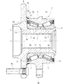
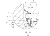
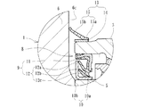
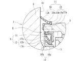
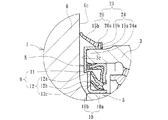
図1は、本発明に係る車輪用軸受装置の第1の実施形態を示す縦断面図、図2は、図1の要部拡大図、図3は、図2の変形例を示す要部拡大図である。なお、以下の説明では、車両に組み付けた状態で車両の外側寄りとなる側をアウター側(図1の左側)、中央寄り側をインナー側(図1の右側)という。
Hereinafter, embodiments of the present invention will be described in detail with reference to the drawings.
FIG. 1 is a longitudinal sectional view showing a first embodiment of a wheel bearing device according to the present invention, FIG. 2 is an enlarged view of a main part of FIG. 1, and FIG. 3 is an enlarged main part of a modification of FIG. FIG. In the following description, the side closer to the outer side of the vehicle when assembled to the vehicle is referred to as the outer side (left side in FIG. 1), and the side closer to the center is referred to as the inner side (right side in FIG. 1).
この車輪用軸受装置は第2世代と呼称される駆動輪用であって、ハブ輪1と車輪用軸受2とからなり、車輪用軸受2は、外方部材3と、複列の転動体(円錐ころ)4、4を介して内嵌された一対の内輪5、5とを備えている。
This wheel bearing device is for a drive wheel called a second generation, and is composed of a hub wheel 1 and a wheel bearing 2, and the wheel bearing 2 is composed of an
ハブ輪1は、一端部に車輪(図示せず)を取り付けるための車輪取付フランジ6を一体に有し、この車輪取付フランジ6から軸方向に延びる小径段部1aが形成され、内周にトルク伝達用のセレーション(またはスプライン)1bが形成されている。車輪取付フランジ6にはハブボルト6aが周方向等配に植設されている。車輪用軸受2は、ハブ輪1の小径段部1aに所定のシメシロを介して圧入され、小径段部1aの端部を径方向外方に塑性変形させて形成した加締部1cによってハブ輪1に対して軸方向に固定されている。
The hub wheel 1 integrally has a
ハブ輪1はS53C等の炭素0.40〜0.80wt%を含む中高炭素鋼で形成され、車輪取付フランジ6のインナー側に円弧状に形成された基部6bから肩部1dを介して小径段部1aに亙って高周波焼入れによって表面硬さを58〜64HRCの範囲に硬化処理されている。これにより、車輪取付フランジ6に負荷される回転曲げ荷重に対して充分な機械的強度を有し、内輪5、5の嵌合部となる小径段部1aの耐フレッティング性が向上する。
The hub wheel 1 is made of medium and high carbon steel containing 0.40 to 0.80 wt% of carbon such as S53C, and has a small diameter step from a
車輪用軸受2の外方部材3は、外周にナックル(図示せず)に取り付けられるための車体取付フランジ3bを一体に有し、内周にそれぞれ外向きに開いたテーパ状の複列の外側転走面3a、3aが一体に形成されている。この外方部材3はS53C等の炭素0.40〜0.80wt%を含む中高炭素鋼で形成され、複列の外側転走面3a、3aが高周波焼入れによって表面硬さを58〜64HRCの範囲に硬化処理されている。
The
一方、内輪5の外周には、前記複列の外側転走面3a、3aに対向するテーパ状の内側転走面5aと、この内側転走面5aの大径側に転動体4を案内する大鍔5b、および小径側に転動体4の脱落を防止するための小鍔5cがそれぞれ形成されている。内輪5および転動体4はSUJ2等の高炭素クロム鋼で形成され、ズブ焼入れによって芯部まで58〜64HRCの範囲に硬化処理されている。そして、外方部材3と一対の内輪5、5の両転走面間に複列の転動体4、4が収容され、保持器7、7によって転動自在に保持されている。この車輪用軸受2は、ハブ輪1の肩部1dに当接され、内輪5の小鍔5cがそれぞれ突合せ状態で衝合する、所謂背面合せタイプの複列円錐ころ軸受からなる。
On the other hand, on the outer periphery of the
また、外方部材3と内輪5との間に形成される環状空間の開口部にはシール8、8が装着されている。これらのシール8、8によって、軸受内部に封入されたグリースの外部への漏洩と、外部から雨水やダスト等が軸受内部に侵入するのを防止している。このシール8は、図2に拡大して示すように、断面が略L字状をなして互いに対向配置された環状のシール板9とスリンガ10とからなるパックシールを構成している。シール板9は、外方部材3の端部内周に圧入される芯金11と、この芯金11に一体に加硫接着されたシール部材12とからなる。芯金11は、オーステナイト系ステンレス鋼鈑(JIS規格のSUS304系等)、あるいは、防錆処理された冷間圧延鋼鈑(JIS規格のSPCC系等)からプレス加工にて断面が略L字状に形成されている。
Further, seals 8 and 8 are attached to an opening of an annular space formed between the
一方、スリンガ10は、オーステナイト系ステンレス鋼鈑(JIS規格のSUS304系等)、あるいは、防錆処理された冷間圧延鋼鈑(JIS規格のSPCC系等)からプレス加工にて断面が略L字状に形成され、内輪5の外径に圧入される円筒部10aと、この円筒部10aから径方向外方に延びる立板部10bとからなる。そして、シール部材12に一体に形成された一対のサイドリップ12a、12bがこのスリンガ10の立板部10bに摺接すると共に、円筒部10aにはラジアルリップ12cが摺接している。
On the other hand, the
さらに、本実施形態では、外方部材3の端部外周にバックアップシール13が圧入されている。このバックアップシール13は、円筒状の芯金14と、この芯金14に一体に加硫接着されたシール部材15とからなる。芯金14は、オーステナイト系ステンレス鋼鈑(JIS規格のSUS304系等)、あるいは、防錆処理された冷間圧延鋼鈑(JIS規格のSPCC系等)からプレス加工にて円筒状に形成されている。一方、シール部材15は、芯金14のインナー側の端部に固着された基部15aと、この基部15aから径方向外方に傾斜して延び、先端部が拡径するラッパ状に形成されたサイドリップ15bとからなる。このサイドリップ15bは、車輪取付フランジ6のインナー側の側面6cに摺接され、雨水やダスト等が前記シール8に直接侵入するのを防止している。
Furthermore, in this embodiment, the
本実施形態では、こうした構成のバックアップシール13を採用することにより、車輪取付フランジ6と外方部材3の端部とが近接した構造であっても、シール部材15のスペースを充分に確保することができ、サイドリップ15bの適切な接触圧を有する最適設計ができる。すなわち、サイドリップ15bに適切な剛性を持たせ、リップ摩耗によってシメシロが変動して密封性が低下するのを防止することができると共に、密封性能の向上を図り、軸受性能を長期間に亘って維持することができる車輪用軸受装置を提供することができる。
In the present embodiment, by employing the
なお、ここでは、駆動輪側の第2世代構造を例示したが、本発明に係る車輪用軸受装置はこれに限らず、外方部材3の外周に車体取付フランジ3bを有していれば良く、第3または第4世代構造であっても良い。また、従動輪側であっても良い。さらに、本実施形態では、転動体4に円錐ころを使用した複列円錐ころ軸受を例示したが、これに限らず、転動体4にボールを使用した複列アンギュラ玉軸受であっても良い。
In addition, although the 2nd generation structure by the side of a drive wheel was illustrated here, the wheel bearing apparatus which concerns on this invention should just have the vehicle
図3に、図2のバックアップシール13の変形例を示す。このバックアップシール16は、芯金14と、この芯金14に一体に加硫接着されたシール部材17とからなる。このシール部材17の基部17aは、芯金14のインナー側の端部を覆うように固着されている。これにより、芯金14の表面が外部に露出することがなく、高価なオーステナイト系ステンレス鋼鈑等から比較的廉価な冷間圧延鋼鈑(JIS規格のSPCC系等)に変更することができるため低コスト化を図ることができる。
FIG. 3 shows a modification of the
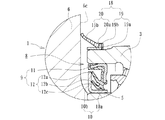
図4は、本発明に係る車輪用軸受装置の第2の実施形態を示す要部拡大図である。この実施形態は、基本的には前述した実施形態とバックアップシールの芯金の構成が一部異なるだけで、その他前述した実施形態と同一部品あるいは同一の機能を有する部位には同じ符号を付して詳細な説明を省略する。 FIG. 4 is an enlarged view showing a main part of a second embodiment of the wheel bearing device according to the present invention. This embodiment basically differs from the above-described embodiment only in the configuration of the core of the backup seal, and other parts having the same parts or the same functions as those of the above-described embodiment are denoted by the same reference numerals. Detailed description is omitted.
本実施形態では、外方部材3の端部外周に圧入されたバックアップシール18は、芯金19と、この芯金19に一体に加硫接着されたシール部材20とからなる。芯金19は、冷間圧延鋼鈑からプレス加工にて断面が略L字状に形成され、外方部材3の端部外周に圧入される円筒状の嵌合部19aと、この嵌合部19aのインナー側の端部から径方向外方に折曲された凸部19bとを有している。
In this embodiment, the
一方、シール部材20は、芯金19の凸部19bを覆うように固着された基部20aと、この基部20aから径方向外方に傾斜して延び、先端部が拡径するラッパ状に形成されたサイドリップ15bとからなる。こうした構成により芯金19の剛性が高くなり、バックアップシール18の抜け耐力が増大して信頼性が向上すると共に、サイドリップ15bの接触圧を維持することができ、長期間に亘って所望の密封性を確保することができる。
On the other hand, the sealing
図5は、本発明に係る車輪用軸受装置の第3の実施形態を示す要部拡大図である。この実施形態は、基本的には前述した第2の実施形態とバックアップシールの芯金の構成が一部異なるだけで、その他前述した実施形態と同一部品あるいは同一の機能を有する部位には同じ符号を付して詳細な説明を省略する。 FIG. 5 is an enlarged view of a main part showing a third embodiment of the wheel bearing device according to the present invention. This embodiment is basically different from the second embodiment described above only in the configuration of the core of the backup seal, and other parts having the same parts or the same functions as those of the above-described embodiment have the same reference numerals. The detailed description is omitted.
本実施形態では、外方部材3の端部外周に圧入されたバックアップシール21は、芯金22と、この芯金22に一体に加硫接着されたシール部材20とからなる。芯金22は、冷間圧延鋼鈑からプレス加工にて断面が略Z字状に形成され、外方部材3の端部外周に圧入される円筒状の嵌合部19aと、この嵌合部19aのインナー側の端部から径方向外方に折曲された凸部19b、および嵌合部19aのアウター側の端部から径方向内方に延び、外方部材3の端面3cに密着する鍔部22aを有している。こうした構成により芯金19の剛性が一層高くなり、バックアップシール21の抜け耐力が一層増大して信頼性が向上すると共に、シール圧入治具の当接面積が増大し、圧入性と位置決め精度が向上する。
In this embodiment, the
図6に、図5のバックアップシール21の変形例を示す。このバックアップシール23は、芯金24と、この芯金24に一体に加硫接着されたシール部材20とからなる。芯金24は、冷間圧延鋼鈑からプレス加工にて断面が略Z字状に形成され、外方部材3の端部外周に圧入される円筒状の嵌合部19aと、この嵌合部19aのインナー側の端部から径方向外方に折曲された凸部19b、および嵌合部19aのアウター側の端部から径方向内方に延び、外方部材3の端面3cに密着する鍔部24aを有している。この鍔部24aの内径は、前述したスリンガ10の外径よりも小径に設定され、シール8との間にラビリンスシールを構成している。これにより、バックアップシール23から泥水等が浸入してもシール8の密封性を向上させることができる。
FIG. 6 shows a modification of the
図7は、本発明に係る車輪用軸受装置の第4の実施形態を示す要部拡大図である。この実施形態は、基本的には前述した第3の実施形態(図5)とリップ摺接部の構成が異なるだけで、その他前述した実施形態と同一部品あるいは同一の機能を有する部位には同じ符号を付して詳細な説明を省略する。 FIG. 7 is an enlarged view of a main part showing a fourth embodiment of the wheel bearing device according to the present invention. This embodiment is basically the same as the above-described third embodiment (FIG. 5) except for the configuration of the lip sliding contact portion, and the same parts or parts having the same functions as the above-described embodiment. Reference numerals are assigned and detailed description is omitted.
本実施形態では、車輪取付フランジ6のインナー側の側面6cに密着して金属環25が装着されている。そして、バックアップシール21のサイドリップ15bがこの金属環25に所定の接触圧で摺接されている。この金属環25は、防錆能を有する鋼板、例えば、オーステナイト系ステンレス鋼鈑(JIS規格のSUS304系等)、あるいは、防錆処理された冷間圧延鋼鈑(JIS規格のSPCC系等)からプレス加工にて形成され、固定ボルト(図示せず)によって車輪取付フランジ6に締結されている。なお、金属環25は、車輪取付フランジ6の側面6cとの密着性を高めるために、図示しないパッキンを介して締結されるのが好ましい。
In the present embodiment, the
こうした構成により、ハブ輪1と車輪用軸受2との間の狭い環状空間に泥水等が滞留して車輪取付フランジ6の側面6cが発錆しても、リップ摺接面の発錆を防止することができ、長期間に亘ってリップ摩耗を防止して密封性を向上させることができる。
With such a configuration, even if muddy water or the like stays in the narrow annular space between the hub wheel 1 and the wheel bearing 2 and the
以上、本発明の実施の形態について説明を行ったが、本発明はこうした実施の形態に何等限定されるものではなく、あくまで例示であって、本発明の要旨を逸脱しない範囲内において、さらに種々なる形態で実施し得ることは勿論のことであり、本発明の範囲は、特許請求の範囲の記載によって示され、さらに特許請求の範囲に記載の均等の意味、および範囲内のすべての変更を含む。 The embodiment of the present invention has been described above, but the present invention is not limited to such an embodiment, and is merely an example, and various modifications can be made without departing from the scope of the present invention. Of course, the scope of the present invention is indicated by the description of the scope of claims, and further, the equivalent meanings described in the scope of claims and all modifications within the scope of the scope of the present invention are included. Including.
本発明に係る車輪用軸受装置は、駆動輪用、従動輪用に拘わらず、第2乃至第4世代構造の車輪用軸受装置に適用することができる。 The wheel bearing device according to the present invention can be applied to a wheel bearing device having a second to fourth generation structure regardless of whether it is for driving wheels or driven wheels.
1・・・・・・・・・・・・・・・・ハブ輪
1a・・・・・・・・・・・・・・・小径段部
1b・・・・・・・・・・・・・・・セレーション
1c・・・・・・・・・・・・・・・加締部
1d・・・・・・・・・・・・・・・肩部
2・・・・・・・・・・・・・・・・車輪用軸受
3・・・・・・・・・・・・・・・・外方部材
3a・・・・・・・・・・・・・・・外側転走面
3b・・・・・・・・・・・・・・・車体取付フランジ
3c・・・・・・・・・・・・・・・外方部材の端面
4・・・・・・・・・・・・・・・・転動体
5・・・・・・・・・・・・・・・・内輪
5a・・・・・・・・・・・・・・・内側転走面
5b・・・・・・・・・・・・・・・大鍔
5c・・・・・・・・・・・・・・・小鍔
6・・・・・・・・・・・・・・・・車輪取付フランジ
6a・・・・・・・・・・・・・・・ハブボルト
6b、15a、20a・・・・・・・基部
6c・・・・・・・・・・・・・・・車輪取付フランジのインナー側の側面
7・・・・・・・・・・・・・・・・保持器
8・・・・・・・・・・・・・・・・シール
9・・・・・・・・・・・・・・・・シール板
10・・・・・・・・・・・・・・・スリンガ
10a・・・・・・・・・・・・・・円筒部
10b・・・・・・・・・・・・・・立板部
11、14、19、22、24・・・芯金
12、15、17、20・・・・・・シール部材
12a、12b、15b・・・・・・サイドリップ
12c、20b・・・・・・・・・・ラジアルリップ
13、16、18、21、23・・・バックアップシール
19a・・・・・・・・・・・・・・嵌合部
19b・・・・・・・・・・・・・・凸部
22a、24a・・・・・・・・・・鍔部
25・・・・・・・・・・・・・・・金属環
51・・・・・・・・・・・・・・・ハブ輪
51a・・・・・・・・・・・・・・小径段部
51b・・・・・・・・・・・・・・セレーション
51c・・・・・・・・・・・・・・加締部
52・・・・・・・・・・・・・・・車輪用軸受
53・・・・・・・・・・・・・・・外方部材
53a・・・・・・・・・・・・・・外側転走面
53b・・・・・・・・・・・・・・車体取付フランジ
54・・・・・・・・・・・・・・・円錐ころ
55・・・・・・・・・・・・・・・内輪
55a・・・・・・・・・・・・・・内側転走面
55b・・・・・・・・・・・・・・大鍔
55c・・・・・・・・・・・・・・小鍔
56・・・・・・・・・・・・・・・車輪取付フランジ
56a・・・・・・・・・・・・・・ハブボルト
56b、65a・・・・・・・・・・基部
56c・・・・・・・・・・・・・・インナー側の側面
57・・・・・・・・・・・・・・・保持器
58・・・・・・・・・・・・・・・シール
59・・・・・・・・・・・・・・・シール板
60・・・・・・・・・・・・・・・スリンガ
60a・・・・・・・・・・・・・・円筒部
60b・・・・・・・・・・・・・・立板部
61、64・・・・・・・・・・・・芯金
62、65・・・・・・・・・・・・シール部材
62a、62b、65b・・・・・・サイドリップ
62c・・・・・・・・・・・・・・ラジアルリップ
63・・・・・・・・・・・・・・・バックアップシール
66・・・・・・・・・・・・・・・金属環
67・・・・・・・・・・・・・・・固定ボルト
1 ・ ・ ・ ・ ・ ・ ・ ・ ・ ・ ・ Hub wheel 1a ・ ・ ・ ・ ・ ・ ・ ・ ・ ・ ・
Claims (6)
一端部に車輪を取り付けるための車輪取付フランジを一体に有し、外周に小径段部が形成されたハブ輪、およびこのハブ輪に嵌合された内輪または等速自在継手の外側継手部材からなり、外周に前記複列の外側転走面に対向する複列の内側転走面が形成された内方部材と、
この内方部材と前記外方部材の両転走面間に保持器を介して転動自在に収容された複列の転動体と、
前記外方部材と内方部材とで形成される環状空間の開口部に装着されたシールとを備えた車輪用軸受装置において、
前記外方部材のアウター側の端部にバックアップシールが装着され、このバックアップシールが、前記外方部材の端部外周に圧入される円筒状の嵌合部を有する芯金と、この芯金に一体に加硫接着されたシール部材とからなると共に、当該シール部材が、径方向外方に傾斜して延び、先端部が拡径するラッパ状に形成されて前記車輪取付フランジのインナー側の側面に摺接されたサイドリップを有し、このサイドリップの基部が前記芯金のインナー側の端部に固着されていることを特徴とする車輪用軸受装置。 An outer member integrally having a vehicle body mounting flange to be attached to the suspension device on the outer periphery, and an outer rolling surface of a double row integrally formed on the inner periphery;
It consists of a hub ring that has a wheel mounting flange for mounting a wheel at one end and a small-diameter step formed on the outer periphery, and an outer ring member of an inner ring or constant velocity universal joint fitted to this hub ring. An inner member in which a double row inner rolling surface facing the double row outer rolling surface is formed on the outer periphery;
A double row rolling element housed between the rolling surfaces of the inner member and the outer member so as to be freely rollable via a cage;
In the wheel bearing device provided with a seal attached to an opening of the annular space formed by the outer member and the inner member,
A back-up seal is attached to the outer end of the outer member, and the back-up seal has a cylindrical fitting that is press-fitted into the outer periphery of the end of the outer member. The seal member is integrally vulcanized and bonded, and the seal member extends in a radially outward direction and is formed in a trumpet shape in which a tip end portion is enlarged, and the side surface on the inner side of the wheel mounting flange A wheel bearing device, comprising: a side lip that is slidably contacted with the base lip, and a base portion of the side lip is fixed to an inner end of the cored bar.
Priority Applications (2)
| Application Number | Priority Date | Filing Date | Title |
|---|---|---|---|
| JP2007321545A JP2009144792A (en) | 2007-12-13 | 2007-12-13 | Bearing device for wheel |
| PCT/JP2008/003047 WO2009057269A1 (en) | 2007-10-31 | 2008-10-27 | Bearing device for wheel |
Applications Claiming Priority (1)
| Application Number | Priority Date | Filing Date | Title |
|---|---|---|---|
| JP2007321545A JP2009144792A (en) | 2007-12-13 | 2007-12-13 | Bearing device for wheel |
Publications (1)
| Publication Number | Publication Date |
|---|---|
| JP2009144792A true JP2009144792A (en) | 2009-07-02 |
Family
ID=40915622
Family Applications (1)
| Application Number | Title | Priority Date | Filing Date |
|---|---|---|---|
| JP2007321545A Pending JP2009144792A (en) | 2007-10-31 | 2007-12-13 | Bearing device for wheel |
Country Status (1)
| Country | Link |
|---|---|
| JP (1) | JP2009144792A (en) |
Citations (8)
| Publication number | Priority date | Publication date | Assignee | Title |
|---|---|---|---|---|
| JP2005061616A (en) * | 2003-07-25 | 2005-03-10 | Ntn Corp | Wheel support bearing assembly |
| JP2005233287A (en) * | 2004-02-19 | 2005-09-02 | Nsk Ltd | Rolling bearing unit for wheel support |
| JP2007100826A (en) * | 2005-10-04 | 2007-04-19 | Ntn Corp | Wheel bearing device |
| JP2007132454A (en) * | 2005-11-11 | 2007-05-31 | Ntn Corp | Wheel bearing unit |
| JP2007177814A (en) * | 2005-12-27 | 2007-07-12 | Jtekt Corp | SEALING DEVICE AND ROLLING BEARING DEVICE USING THE SAME |
| JP2007187225A (en) * | 2006-01-12 | 2007-07-26 | Ntn Corp | Bearing device for wheel |
| JP2007192392A (en) * | 2006-01-23 | 2007-08-02 | Ntn Corp | Bearing device for wheel |
| JP2007270960A (en) * | 2006-03-31 | 2007-10-18 | Jtekt Corp | Wheel bearing device |
-
2007
- 2007-12-13 JP JP2007321545A patent/JP2009144792A/en active Pending
Patent Citations (8)
| Publication number | Priority date | Publication date | Assignee | Title |
|---|---|---|---|---|
| JP2005061616A (en) * | 2003-07-25 | 2005-03-10 | Ntn Corp | Wheel support bearing assembly |
| JP2005233287A (en) * | 2004-02-19 | 2005-09-02 | Nsk Ltd | Rolling bearing unit for wheel support |
| JP2007100826A (en) * | 2005-10-04 | 2007-04-19 | Ntn Corp | Wheel bearing device |
| JP2007132454A (en) * | 2005-11-11 | 2007-05-31 | Ntn Corp | Wheel bearing unit |
| JP2007177814A (en) * | 2005-12-27 | 2007-07-12 | Jtekt Corp | SEALING DEVICE AND ROLLING BEARING DEVICE USING THE SAME |
| JP2007187225A (en) * | 2006-01-12 | 2007-07-26 | Ntn Corp | Bearing device for wheel |
| JP2007192392A (en) * | 2006-01-23 | 2007-08-02 | Ntn Corp | Bearing device for wheel |
| JP2007270960A (en) * | 2006-03-31 | 2007-10-18 | Jtekt Corp | Wheel bearing device |
Similar Documents
| Publication | Publication Date | Title |
|---|---|---|
| JP5836584B2 (en) | Wheel bearing device | |
| JP6603078B2 (en) | Wheel bearing device | |
| JP6275465B2 (en) | SEALING DEVICE AND WHEEL BEARING DEVICE HAVING THE SAME | |
| JP2009197884A (en) | Wheel bearing device | |
| WO2008044328A1 (en) | Bearing device for wheel | |
| JP2012056411A (en) | Wheel bearing device | |
| JP2010053893A (en) | Wheel-bearing device | |
| JP5468751B2 (en) | Wheel bearing device | |
| JP2011007272A (en) | Wheel bearing device | |
| JP5179841B2 (en) | Wheel bearing device | |
| JP2007100826A (en) | Wheel bearing device | |
| JP2011089558A (en) | Wheel bearing device | |
| JP2012017019A (en) | Bearing device for wheel | |
| JP4697792B2 (en) | Wheel bearing device | |
| JP2007285322A (en) | Bearing device for wheel | |
| JP2007192392A (en) | Bearing device for wheel | |
| JP4679325B2 (en) | Wheel bearing device | |
| JP4812112B2 (en) | Wheel bearing device | |
| JP2009292303A (en) | Bearing device for wheel | |
| JP2008032067A (en) | Bearing device for wheel | |
| JP4807804B2 (en) | Wheel bearing device | |
| JP5414964B2 (en) | Wheel bearing device | |
| JP2008163978A (en) | Wheel bearing device | |
| JP2018080840A (en) | Sealing device and bearing device for wheel having the same | |
| JP5083861B2 (en) | Wheel bearing device |
Legal Events
| Date | Code | Title | Description |
|---|---|---|---|
| A621 | Written request for application examination |
Effective date: 20101126 Free format text: JAPANESE INTERMEDIATE CODE: A621 |
|
| A131 | Notification of reasons for refusal |
Effective date: 20121213 Free format text: JAPANESE INTERMEDIATE CODE: A131 |
|
| A02 | Decision of refusal |
Free format text: JAPANESE INTERMEDIATE CODE: A02 Effective date: 20130509 |