JP2009161902A - Reinforcement joint implement - Google Patents
Reinforcement joint implement Download PDFInfo
- Publication number
- JP2009161902A JP2009161902A JP2007338998A JP2007338998A JP2009161902A JP 2009161902 A JP2009161902 A JP 2009161902A JP 2007338998 A JP2007338998 A JP 2007338998A JP 2007338998 A JP2007338998 A JP 2007338998A JP 2009161902 A JP2009161902 A JP 2009161902A
- Authority
- JP
- Japan
- Prior art keywords
- wedge
- insertion hole
- wedge insertion
- edge
- bar
- Prior art date
- Legal status (The legal status is an assumption and is not a legal conclusion. Google has not performed a legal analysis and makes no representation as to the accuracy of the status listed.)
- Granted
Links
- 230000002787 reinforcement Effects 0.000 title abstract description 16
- 238000003780 insertion Methods 0.000 claims abstract description 80
- 230000037431 insertion Effects 0.000 claims abstract description 80
- 229910000831 Steel Inorganic materials 0.000 claims abstract description 40
- 239000010959 steel Substances 0.000 claims abstract description 40
- 230000003014 reinforcing effect Effects 0.000 claims description 119
- 238000000034 method Methods 0.000 description 10
- 239000011796 hollow space material Substances 0.000 description 9
- 239000011150 reinforced concrete Substances 0.000 description 2
- 235000014676 Phragmites communis Nutrition 0.000 description 1
- 229910001294 Reinforcing steel Inorganic materials 0.000 description 1
- 238000005452 bending Methods 0.000 description 1
- 239000004567 concrete Substances 0.000 description 1
- 239000004615 ingredient Substances 0.000 description 1
- 238000009434 installation Methods 0.000 description 1
- 210000003205 muscle Anatomy 0.000 description 1
- 238000012797 qualification Methods 0.000 description 1
- 230000000452 restraining effect Effects 0.000 description 1
- 238000003466 welding Methods 0.000 description 1
Images




Landscapes
- Reinforcement Elements For Buildings (AREA)
Abstract
Description
本発明は、鉄筋同士、特に配筋済みの鉄筋に接合する際に適用される鉄筋継手具に関する。 The present invention relates to a reinforcing bar joint applied when connecting reinforcing bars to each other, in particular, reinforcing bars that have already been arranged.
鉄筋コンクリート構造(RC造)や鉄骨鉄筋コンクリート構造(SRC造)の主たる構成要素である鉄筋は、配筋する際の作業性等を勘案して所定長さに加工されるため、鉄筋同士を現場で接合する作業が不可欠となる。 Reinforcing bars, which are the main components of reinforced concrete structures (RC structures) and steel-framed reinforced concrete structures (SRC structures), are processed to a predetermined length in consideration of workability when placing the reinforcing bars, so the reinforcing bars are joined together on site. The work to do becomes indispensable.
鉄筋同士を接合する方法としては、重ね継手、機械式継手、ガス圧接継手等のさまざまな種類があり、構造体に求められる品質や作業条件あるいは使用される鉄筋径等によって適宜使い分けることになる。 There are various types of methods for joining the reinforcing bars, such as lap joints, mechanical joints, gas pressure welding joints, and the like, which are properly used depending on the quality required for the structure, the working conditions, the diameter of the reinforcing bars used, and the like.
ここで、上述した接合方法にはそれぞれ一長一短があり、重ね継手はコンクリートとの付着を利用することで簡単に鉄筋同士を接合できる反面、2本の鉄筋を重ね合わせるため、鉄筋径が太くなればなるほど、鉄筋間にあきを確保したり重ね長さを確保したりすることが難しくなる。また、機械式継手はカプラーへの鉄筋の挿入長さや締付けトルクといった項目を管理する必要があり、ガス圧接継手は作業にあたって資格が必要となる。 Here, each of the joining methods described above has advantages and disadvantages, and lap joints can easily join rebars by using adhesion to concrete, but in order to overlap two rebars, if the rebar diameter increases Indeed, it becomes difficult to secure a space between the reinforcing bars and a length of the overlap. In addition, it is necessary to manage items such as the insertion length of the reinforcing bar to the coupler and the tightening torque for the mechanical joint, and the gas pressure joint requires qualification for work.
そのため、鉄筋を簡単に接合可能でかつ重ね長さを確保する必要がない鉄筋の接合方法も別途開発されているが、それらのうち、互いに平行な2本の鉄筋をまとめて接合する方法では、決まった間隔の鉄筋にしか適用することができず、鉄筋のピッチに関して汎用性に欠ける(特許文献1参照)。また、U字形の筒体を用いた接合方法では、十分な継手強度を確保することができない(特許文献2,3参照)。
For this reason, reinforcing bar joining methods that can easily join reinforcing bars and do not need to secure the overlap length have been developed separately. Among them, in the method of joining two reinforcing bars that are parallel to each other, It can be applied only to reinforcing bars with a fixed interval, and lacks versatility regarding the pitch of reinforcing bars (see Patent Document 1). Moreover, in the joining method using a U-shaped cylinder, sufficient joint strength cannot be ensured (see
かかる状況下、断面が長円状をなす鋼製の筒体と楔部材とからなる接合具が開発されており、かかる接合具によれば、筒体内に2本の鉄筋端部をそれぞれ逆方向から挿入し、次いで筒体に設けられた楔挿通孔から2本の鉄筋の間に楔部材を打込むことにより、鉄筋を相互に接合することができる(特許文献4及び特許文献5参照)。 Under such circumstances, a joining tool composed of a steel cylinder having an oval cross section and a wedge member has been developed, and according to such a joining tool, the two reinforcing bar ends are respectively reversed in the cylinder. Then, the reinforcing bars can be joined to each other by driving a wedge member between the two reinforcing bars through a wedge insertion hole provided in the cylindrical body (see Patent Document 4 and Patent Document 5).
しかしながら、接合先の鉄筋の配筋や組立が既に終わっている場合、該鉄筋を鋼製の筒体に挿入することができず、接合元の鉄筋を接合することができないという問題を生じていた。例えば、接合先の鉄筋が鉄筋籠として既に組み立てられている場合、特許文献4,5の接合具では、鉄筋籠を構成する鉄筋に別の鉄筋を接合することは不可能である。 However, when the reinforcing bars have already been arranged and assembled, the reinforcing bars cannot be inserted into the steel cylinder, and the joining reinforcing bars cannot be joined. . For example, in the case where the reinforcing steel bars to be joined are already assembled as reinforcing bar rods, it is impossible to join another reinforcing bar to the reinforcing bars constituting the reinforcing bar rods with the joints disclosed in Patent Documents 4 and 5.
本発明は、上述した事情を考慮してなされたもので、鉄筋同士を接合する際、一方の鉄筋が既に組み立てられていたり配筋が終了している場合であっても接合が可能な鉄筋継手具を提供することを目的とする。 The present invention has been made in consideration of the above-described circumstances, and when joining reinforcing bars, a reinforcing bar joint that can be joined even if one of the reinforcing bars has already been assembled or the arrangement of the reinforcing bars has been completed. The purpose is to provide ingredients.
上記目的を達成するため、本発明に係る鉄筋継手具は請求項1に記載したように、接合対象である2本の鉄筋を並列状態で抱き込むことができるようにかつ一方の縁部が他方の縁部に重なるように湾曲形成され前記一方の縁部に第1の楔挿通孔が形成され該第1の楔挿通孔と同芯になるように前記他方の縁部に第2の楔挿通孔が形成され前記第1の楔挿通孔及び前記第2の楔挿通孔と同芯になるように前記一方の縁部及び前記他方の縁部の対向位置に第3の楔挿通孔が形成された開断面の鋼製筒状体と、前記第1の楔挿通孔、前記第2の楔挿通孔及び前記第3の楔挿通孔に挿通され前記2本の鉄筋の間に圧入される楔部材とから構成したものである。
In order to achieve the above-mentioned object, a reinforcing bar joint according to the present invention, as described in
また、本発明に係る鉄筋継手具は請求項2に記載したように、U字状断面をなすとともに対向する各平板部に楔挿通孔が同芯に形成され相互に嵌め入れることが可能な一対の半円筒状部材と、接合対象である2本の鉄筋を並列状態で抱き込むようにして前記一対の半円筒状部材を相互に嵌め入れたとき、前記半円筒状部材にそれぞれ形成された2組の楔挿通孔に挿通され前記2本の鉄筋の間に圧入される楔部材とから構成したものである。
Further, as described in
従来の鉄筋継手具を用いて鉄筋を接合するには、楔部材を打ち込む前に接合対象となる2本の鉄筋を筒体内に挿通しておかねばならない。そのため、既に組立や配筋が終了している場合には、接合対象以外の鉄筋が邪魔になり、接合対象の鉄筋を筒体内に挿通することができない事態が起こり得る。例えば、柱の主筋に梁の下端筋を接合しようとしても、主筋が鉄筋籠の一部として既に組み立てられている場合には、フープ筋が邪魔になって主筋を筒体に挿通することができない。 In order to join a reinforcing bar using a conventional reinforcing bar joint, two reinforcing bars to be joined must be inserted into the cylinder before the wedge member is driven. For this reason, when the assembly and the bar arrangement have already been completed, the reinforcing bars other than the joining target may be in the way and the joining target reinforcing bars cannot be inserted into the cylinder. For example, even if you try to join the bottom bar of the beam to the main bar of the column, if the main bar is already assembled as part of the reinforcing bar rod, the hoop bar will interfere and the main bar cannot be inserted into the cylinder. .
本出願人は、筒体を閉断面ではなく開断面とするとともに、並列配置された2本の鉄筋を抱き込むようにして筒体を取り付け、その状態で楔部材を打ち込めば、組立済みの鉄筋や配筋済みの鉄筋に対しても接合可能であることに着眼し、研究開発を行った。 The present applicant makes the cylindrical body an open cross section instead of a closed cross section, attaches the cylindrical body so as to embrace the two rebars arranged in parallel, and drives the wedge member in that state. Focusing on the fact that it can be joined to rebars that have already been reinforced, R & D was conducted.
しかし、従来の鉄筋継手具においては、楔部材を打ち込むことによって、2本の鉄筋が筒体内面から大きな反力を受け、その反力が楔部材からの圧入力とともに拘束力となって2本の鉄筋を強固に接合できたのに対し、開断面の筒体では、楔部材を打ち込んでも、筒体が開いたり逃げたりするため、十分な反力が発生しない。 However, in the conventional reinforcing bar joint tool, when the wedge member is driven, the two reinforcing bars receive a large reaction force from the inner surface of the cylindrical body, and the reaction force becomes a restraining force together with the pressure input from the wedge member. On the other hand, in the case of a cylindrical body having an open cross section, even when a wedge member is driven, the cylindrical body opens or escapes, so that a sufficient reaction force is not generated.
そこで、本出願人は、開断面であるがゆえの筒体の開きや逃げを楔部材で抑止することにより、筒体内面から十分な反力を鉄筋に作用せしめ、かくして従来の鉄筋継手具と同様、2本の鉄筋を強固に接合することができるというあらたな知見を得た。 Therefore, the present applicant, by suppressing the opening and escaping of the cylindrical body due to the open cross section with a wedge member, causes a sufficient reaction force to act on the reinforcing bar from the inner surface of the cylindrical body, thus Similarly, the new knowledge that two rebars can be joined firmly was acquired.
すなわち、第1の発明に係る鉄筋継手具においては、まず、接合対象である2本の鉄筋を並列状態で抱き込むようにして該鉄筋に鋼製筒状体を取り付ける。取付けにあたっては、鋼製筒状体の可撓性を利用して一方の縁部と他方の縁部との間に隙間をつくり、又は隙間を拡げ、その隙間から鉄筋を鋼製筒状体の中空空間に入れ込む。 That is, in the reinforcing bar joint according to the first aspect of the invention, first, a steel tubular body is attached to the reinforcing bars so as to embrace the two reinforcing bars to be joined in a parallel state. When installing, make use of the flexibility of the steel tubular body to create a gap between one edge and the other edge, or widen the gap, from which the reinforcing bar is connected to the steel tubular body. Put in the hollow space.
2本の鉄筋が例えば梁の下端筋と柱の主筋であって柱の主筋が鉄筋籠の一部である場合を仮に想定した場合、まず、鋼製筒状体の可撓性を利用して一方の縁部と他方の縁部との間に隙間をつくり、又は隙間を拡げ、その隙間を介して柱の主筋を鋼製筒状体の中空空間に入れ込む。この段階では、鋼製筒状体の中空空間に柱の主筋だけが挿通された状態となっているので、引き続き、残りの中空空間に梁の下端筋の端部を挿通することにより、鋼製筒状体で2本の鉄筋を並列状態で抱き込む。 For example, assuming that the two reinforcing bars are the bottom bar of the beam and the main bar of the column, and the main bar of the column is a part of the reinforcing bar rod, first, using the flexibility of the steel tubular body A gap is created between one edge and the other edge, or the gap is widened, and the main bar of the column is inserted into the hollow space of the steel tubular body through the gap. At this stage, since only the main bar of the column has been inserted into the hollow space of the steel tubular body, the end of the lower bar of the beam is continuously inserted into the remaining hollow space, thereby making the steel Hold the two rebars in parallel with the cylindrical body.
次に、楔部材を、第1の楔挿通孔、第2の楔挿通孔及び第3の楔挿通孔に挿通するとともに、2本の鉄筋の間に楔部材を圧入する。 Next, the wedge member is inserted into the first wedge insertion hole, the second wedge insertion hole, and the third wedge insertion hole, and the wedge member is press-fitted between the two reinforcing bars.
このようにすると、楔部材の圧入力が2本の鉄筋を介して鋼製筒状体に伝達し、鋼製筒状体を押し開こうとするが、鋼製筒状体の開きは楔部材によって拘束されている。そのため、鋼製筒状体はその内面で2本の鉄筋に反力を作用させることとなり、かくして2本の鉄筋は、鋼製筒状体及び楔部材によって強固に接合される。 In this case, the pressure input of the wedge member is transmitted to the steel tubular body through the two reinforcing bars, and the steel tubular body is pushed and opened. However, the opening of the steel tubular body is the wedge member. Is restrained by. Therefore, the steel tubular body causes a reaction force to act on the two reinforcing bars on the inner surface thereof, and thus the two reinforcing bars are firmly joined by the steel tubular body and the wedge member.
一方の縁部と他方の縁部との重なりは、両者が接触している状態での重なりだけを意味しているものではなく、むしろ、所定の間隔だけ離間している方が、鉄筋への取付け時に間隔を拡げやすく、利便性が高い。 The overlap between one edge and the other edge does not mean only the overlap when they are in contact with each other, but rather, it is more It is easy to widen the interval during installation and is highly convenient.
また、第2の発明に係る鉄筋継手具においては、まず、接合対象である2本の鉄筋を並列状態で抱き込むようにして一対の半円筒状部材を相互に嵌め入れる。 In the reinforcing bar joint according to the second invention, first, a pair of semi-cylindrical members are fitted into each other so as to embrace the two reinforcing bars to be joined in a parallel state.
2本の鉄筋が例えば梁の下端筋と柱の主筋であって柱の主筋が鉄筋籠の一部である場合を仮に想定した場合、まず、柱の主筋に梁の下端筋端部を添わせて並列状態とし、かかる状態で2本の鉄筋を抱き込むようにして一対の半円筒状部材を相互に嵌め入れる。 For example, assuming that the two reinforcing bars are the bottom bar of the beam and the main bar of the column, and the main bar of the column is a part of the reinforcing bar, first add the end of the lower bar of the beam to the main bar of the column. In this state, a pair of semi-cylindrical members are fitted to each other so as to embrace the two reinforcing bars.
次に、各半円筒状部材に形成された楔挿通孔が同芯になるように、該各半円筒状部材を相対的に位置決めし、次いで、2組の楔挿通孔に楔部材を挿通するとともに、2本の鉄筋の間に楔部材を圧入する。 Next, each semi-cylindrical member is relatively positioned so that the wedge insertion holes formed in each semi-cylindrical member are concentric, and then the wedge members are inserted into the two pairs of wedge insertion holes. At the same time, a wedge member is press-fitted between the two reinforcing bars.
このようにすると、楔部材の圧入力が2本の鉄筋を介して一対の半円筒状部材に伝達し、それらが互いに離間する方向に半円筒状部材を逃がそうとするが、半円筒状部材の逃げは楔部材によって拘束されている。そのため、各半円筒状部材は、それらの内面で2本の鉄筋に反力を作用させることとなり、かくして2本の鉄筋は、一対の半円筒状部材及び楔部材によって強固に接合される。 In this case, the pressure input of the wedge member is transmitted to the pair of semi-cylindrical members via the two reinforcing bars, and the semi-cylindrical members are allowed to escape in the direction in which they are separated from each other. The escape of the member is restrained by a wedge member. Therefore, each semi-cylindrical member causes a reaction force to act on the two reinforcing bars on the inner surface thereof, and thus the two reinforcing bars are firmly joined by the pair of semi-cylindrical members and the wedge member.
以下、本発明に係る鉄筋継手具の実施の形態について、添付図面を参照して説明する。なお、従来技術と実質的に同一の部品等については同一の符号を付してその説明を省略する。 Embodiments of a reinforcing bar joint according to the present invention will be described below with reference to the accompanying drawings. Note that components that are substantially the same as those of the prior art are assigned the same reference numerals, and descriptions thereof are omitted.
(第1実施形態) (First embodiment)
図1は、本実施形態に係る鉄筋継手具を示した図である。同図でわかるように、本実施形態に係る鉄筋継手具1は、接合対象である2本の鉄筋2,3を並列状態で抱き込むことができるように湾曲形成された鋼製筒状体4と、2本の鉄筋2,3の間に圧入される楔部材5とから構成してある。
FIG. 1 is a view showing a reinforcing bar joint according to the present embodiment. As can be seen in the figure, the reinforcing bar joint 1 according to the present embodiment is a steel tubular body 4 that is curved so that the two reinforcing
鋼製筒状体4は、従来の閉断面筒体とは違って開断面の筒状をなしており、一方の縁部6が他方の縁部7に重なるように湾曲形成してある。かかる鋼製筒状体4は、例えば矩形状の鋼板を曲げ加工して形成することができる。なお、一方の縁部6と他方の縁部7との間は、所定の隙間δを設けてあり、この隙間δを拡げることによって、組立済みの鉄筋に取り付けることができるようになっている。
Unlike the conventional closed-section cylinder, the steel cylinder 4 has an open-section cylinder, and is curved so that one
鋼製筒状体4の一方の縁部6には、第1の楔挿通孔としての楔挿通孔8を形成してあるとともに、他方の縁部7には、楔挿通孔8と同芯になるように第2の楔挿通孔としての楔挿通孔9を形成してある。また、一方の縁部6及び他方の縁部7の対向位置には、楔挿通孔8及び楔挿通孔9と同芯になるように、第3の楔挿通孔としての楔挿通孔10を形成してある。
A
楔部材5は、楔挿通孔8、楔挿通孔9及び楔挿通孔10に挿通されるとともに、2本の鉄筋2,3の間に圧入されるように構成してある。
The wedge member 5 is configured to be inserted into the
図2は、本実施形態に係る鉄筋継手具1を用いて梁11の上端筋12と下端筋13を柱14の主筋15にそれぞれ接合した様子を示した側面図であり、柱14の主筋15は、鉄筋籠16の一部として先行組立がなされている。
FIG. 2 is a side view showing a state in which the
梁11の下端筋13を柱14の主筋15に接合するには、まず図3(a)に示すように鋼製筒状体4の可撓性を利用して一方の縁部6と他方の縁部7との間の隙間を拡げ、その隙間を介して柱14の主筋15を鋼製筒状体4の中空空間に入れ込む。
In order to join the
この段階では、鋼製筒状体4の中空空間に柱14の主筋15だけが挿通された状態となっているので、引き続き同図(b)に示したように、残りの中空空間に梁11の下端筋13の端部を挿通することにより、鋼製筒状体4で2本の鉄筋13,15を並列状態で抱き込む。
At this stage, since only the
次に、楔挿通孔8、楔挿通孔9及び楔挿通孔10に楔部材5を挿通するとともに、該楔部材を2本の鉄筋13,15の間に圧入する。
Next, the wedge member 5 is inserted into the
このようにすると、楔部材5の圧入力は、2本の鉄筋13,15を介して鋼製筒状体4に伝達し、該鋼製筒状体を押し開こうとするが、鋼製筒状体4の開きは、楔部材15によって拘束されている。そのため、鋼製筒状体4は、その内面で2本の鉄筋13,15に反力を作用させることとなり、かくして2本の鉄筋13,15は、鋼製筒状体4及び楔部材5によって強固に接合される。梁11の上端筋12についても、上述したと同様な手順で柱14の主筋15に接合することができる。
In this case, the pressure input of the wedge member 5 is transmitted to the steel tubular body 4 through the two reinforcing
以上説明したように、本実施形態に係る鉄筋継手具1によれば、開断面の鋼製筒状体4を、その中空空間に2本の鉄筋を並列状態で抱き込むことができるように湾曲形成するとともに、鋼製筒状体4の一方の縁部6に楔挿通孔8を、他方の縁部7に楔挿通孔9をそれぞれ形成するとともに、対向位置には楔挿通孔10を形成し、それらに楔部材5を挿入するようにしたので、楔部材5を圧入したとき、鋼製筒状体4は、開き方向の変形を生じることなく、2本の鉄筋に反力を及ぼすことが可能となり、従来の閉断面型の筒体を用いた鉄筋継手具と同様、2本の鉄筋を強固に接合することが可能となる。
As described above, according to the reinforcing bar joint 1 according to the present embodiment, the steel tubular body 4 having an open cross section is curved so that the two reinforcing bars can be held in parallel in the hollow space. In addition, a
また、本実施形態に係る鉄筋継手具1によれば、開断面の鋼製筒状体4を用いるようにしたので、鉄筋籠16の一部として既に組立が完了している柱14の主筋15に対しても、柱14のフープ筋が何ら障害となることなく、図3で説明したように一方の縁部6と他方の縁部7との隙間を拡げて主筋15を鋼製筒状体4の中空空間に入れ込むことにより、梁11の下端筋13や上端筋12と強固に接合することが可能となる。
Moreover, according to the reinforcing bar joint 1 according to the present embodiment, since the steel tubular body 4 having an open cross section is used, the
本実施形態では、柱14の鉄筋籠16を構成する主筋15に梁11の上端筋12や下端筋13を接合する場合を取り上げたが、鉄筋継手具1は、適用部位が限定されるものではなく、既に配筋や組立が終了している鉄筋に別の鉄筋を接合するあらゆる場合に適用することが可能である。
In the present embodiment, the case where the
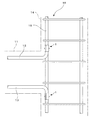
図4は、梁11のスターラップ筋41に床版42の下端筋43を接合した様子を示した側面図である。従来の鉄筋継手具であれば、配筋が終了したスターラップ筋41を筒体に挿通することができず、それゆえ、配筋されたスターラップ筋41に床版42の下端筋43を接合することはできなかったが、本実施形態に係る鉄筋継手具1を用いれば、上述したと同様な手順で、両者を接合することができる。
FIG. 4 is a side view showing a state in which the
また、本実施形態では、楔挿通孔8、楔挿通孔9、楔挿通孔10をそれぞれ一つずつ鋼製筒状体4に形成した例について説明したが、楔挿通孔の個数は1つに限定されるものでなく、各楔挿通孔8、楔挿通孔9、楔挿通孔10をそれぞれ複数形成してもかまわない。
In the present embodiment, the example in which the
(第2実施形態) (Second Embodiment)
次に、第2実施形態について説明する。なお、第1実施形態と実質的に同一の部品等については同一の符号を付してその説明を省略する。 Next, a second embodiment will be described. Note that components that are substantially the same as those of the first embodiment are denoted by the same reference numerals, and description thereof is omitted.
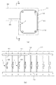
図5は、本実施形態に係る鉄筋継手具51を示した図である。同図でわかるように、本実施形態に係る鉄筋継手具51は、接合対象である2本の鉄筋2,3を並列状態で抱き込む一対の半円筒状部材54a,54bと、2本の鉄筋2,3の間に圧入される楔部材5とから構成してある。
FIG. 5 is a view showing a reinforcing bar joint 51 according to the present embodiment. As can be seen in the figure, the reinforcing bar joint 51 according to the present embodiment includes a pair of
半円筒状部材54aはU字状断面をなし、対向する各平板部56a,56aに楔挿通孔55a,55aを同芯に形成してあるとともに、半円筒状部材54bも半円筒状部材54aと同様、U字状断面をなし、対向する各平板部56b,56bに楔挿通孔55b,55bを同芯に形成してある。
The
これら一対の半円筒状部材54a,54bは、同一構成の部材ではあるが、対称配置して平板部56aあるいは平板部56bの厚みだけずらすことにより、相互に嵌め入れることができるようになっている。
Although the pair of
楔部材5は、2本の鉄筋2,3を並列状態で抱き込むようにして一対の半円筒状部材54a,54bを相互に嵌め入れたとき、半円筒状部材54a,54bにそれぞれ形成された楔挿通孔55a,55a及び楔挿通孔55b,55bに挿通され、2本の鉄筋2,3の間に圧入されるようになっている。
When the pair of
図6は、本実施形態に係る鉄筋継手具51を用いて梁11の下端筋13を柱14の主筋15に接合する手順を示したものである。
FIG. 6 shows a procedure for joining the
鉄筋継手具51を用いて梁11の下端筋13を柱14の主筋15に接合するには、まず接合対象である2本の鉄筋13,15を並列状態で抱き込むようにして、一対の半円筒状部材54a,54bを相互に嵌め入れる。
In order to join the
次に、半円筒状部材54aに形成された楔挿通孔55a,55aと半円筒状部材54bに形成された楔挿通孔55b,55bが同芯になるように、各半円筒状部材54a,54bを相対的に位置決めし、次いで、楔挿通孔55a,55a及び楔挿通孔55b,55bに楔部材5を挿通するとともに、2本の鉄筋13,15の間に楔部材5を圧入する。
Next, each
このようにすると、楔部材5の圧入力は、2本の鉄筋13,15を介して一対の半円筒状部材54a,54bに伝達し、それらが互いに離間する方向に半円筒状部材54a,54bを逃がそうとするが、半円筒状部材54a,54bの逃げは、楔部材5によって拘束されている。そのため、各半円筒状部材54a,54bは、それらの内面で2本の鉄筋13,15に反力を作用させることとなり、かくして2本の鉄筋13,15は、一対の半円筒状部材54a,54b及び楔部材5によって強固に接合される。
In this way, the pressure input of the wedge member 5 is transmitted to the pair of
以上説明したように、本実施形態に係る鉄筋継手具51によれば、半円筒状部材54a,54bを、2本の鉄筋が並列状態で抱き込まれるようにして相互に嵌め入れることができるように構成するとともに、半円筒状部材54a,54bにそれぞれ形成された楔挿通孔55a,55a及び楔挿通孔55b,55bに楔部材5を挿入するようにしたので、楔部材5を圧入したとき、半円筒状部材54a,54bは、互いに離間する方向に逃げることなく、2本の鉄筋に反力を及ぼすことが可能となり、従来の閉断面型の筒体を用いた鉄筋継手具と同様、2本の鉄筋を強固に接合することが可能となる。
As described above, according to the reinforcing bar joint 51 according to the present embodiment, the
また、本実施形態に係る鉄筋継手具51によれば、半円筒状部材54a,54bを用いるようにしたので、鉄筋籠16の一部として既に組立が完了している柱14の主筋15に対しても、柱14のフープ筋が何ら障害となることなく、図6で説明したように梁11の下端筋13と強固に接合することが可能となる。
Further, according to the reinforcing bar joint 51 according to the present embodiment, since the
本実施形態では、柱14の鉄筋籠16を構成する主筋15に梁11の上端筋12や下端筋13を接合する場合を取り上げたが、鉄筋継手具51は、適用部位が限定されるものではなく、既に配筋や組立が終了している鉄筋に別の鉄筋を接合するあらゆる場合に適用することが可能である。
In the present embodiment, the case where the
例えば、第1実施形態で説明したように、梁11のスターラップ筋41に床版42の下端筋43を接合する場合にも鉄筋継手具51を採用することが可能である。
For example, as described in the first embodiment, it is possible to employ the reinforcing bar joint 51 even when the
また、本実施形態では、同一形状同一寸法の半円筒状部材54a,54bで一対の半円筒状部材を構成したが、本発明に係る半円筒状部材はかかる構成に限定されるものではなく、互いに異なる形状や寸法でもかまわない。例えば、一方の半円筒状部材全体が他方の半円筒状部材に嵌め入れられる構成を採用することができる。
Further, in the present embodiment, the pair of semi-cylindrical members are configured by the
また、本実施形態では、半円筒状部材54aに楔挿通孔55a,55aを1組、半円筒状部材54bに楔挿通孔55b,55bを1組それぞれ形成した例について説明したが、かかる楔挿通孔の組数は1組に限定されるものでなく、楔挿通孔55a,55aや楔挿通孔55b,55bを数組設けるようにしてもかまわない。
In the present embodiment, an example in which one set of
1,51 鉄筋継手具
2,3 鉄筋
4 鋼製筒状体
5 楔部材
6 一方の縁部
7 他方の縁部
8 楔挿通孔(第1の楔挿通孔)
9 楔挿通孔(第2の楔挿通孔)
10 楔挿通孔(第3の楔挿通孔)
12 梁の上端筋(鉄筋)
13 梁の下端筋(鉄筋)
15 柱の主筋(鉄筋)
41 スターラップ筋(鉄筋)
43 床版の下端筋(鉄筋)
54a,54b 半円筒状部材
55a,55b 楔挿通孔
56a,56b 平板部
DESCRIPTION OF
9 Wedge insertion hole (second wedge insertion hole)
10 Wedge insertion hole (third wedge insertion hole)
12 Top end of the beam (rebar)
13 Beam bottom reinforcement (rebar)
15 Column main reinforcement (rebar)
41 Stirrup muscle (rebar)
43 Lower floor reinforcement (rebar)
54a, 54b
Claims (2)
Priority Applications (1)
| Application Number | Priority Date | Filing Date | Title |
|---|---|---|---|
| JP2007338998A JP4992143B2 (en) | 2007-12-28 | 2007-12-28 | Rebar fittings |
Applications Claiming Priority (1)
| Application Number | Priority Date | Filing Date | Title |
|---|---|---|---|
| JP2007338998A JP4992143B2 (en) | 2007-12-28 | 2007-12-28 | Rebar fittings |
Publications (2)
| Publication Number | Publication Date |
|---|---|
| JP2009161902A true JP2009161902A (en) | 2009-07-23 |
| JP4992143B2 JP4992143B2 (en) | 2012-08-08 |
Family
ID=40964825
Family Applications (1)
| Application Number | Title | Priority Date | Filing Date |
|---|---|---|---|
| JP2007338998A Active JP4992143B2 (en) | 2007-12-28 | 2007-12-28 | Rebar fittings |
Country Status (1)
| Country | Link |
|---|---|
| JP (1) | JP4992143B2 (en) |
Citations (3)
| Publication number | Priority date | Publication date | Assignee | Title |
|---|---|---|---|---|
| JPS57190855A (en) * | 1981-05-15 | 1982-11-24 | Shinpachi Hamada | Joining of iron wire reinforcing concrete block |
| JPS5864727U (en) * | 1981-10-26 | 1983-05-02 | 清水建設株式会社 | Rebar joint structure |
| JPS6082019U (en) * | 1983-11-11 | 1985-06-06 | 鹿島建設株式会社 | Joints for reinforcing bars |
-
2007
- 2007-12-28 JP JP2007338998A patent/JP4992143B2/en active Active
Patent Citations (3)
| Publication number | Priority date | Publication date | Assignee | Title |
|---|---|---|---|---|
| JPS57190855A (en) * | 1981-05-15 | 1982-11-24 | Shinpachi Hamada | Joining of iron wire reinforcing concrete block |
| JPS5864727U (en) * | 1981-10-26 | 1983-05-02 | 清水建設株式会社 | Rebar joint structure |
| JPS6082019U (en) * | 1983-11-11 | 1985-06-06 | 鹿島建設株式会社 | Joints for reinforcing bars |
Also Published As
| Publication number | Publication date |
|---|---|
| JP4992143B2 (en) | 2012-08-08 |
Similar Documents
| Publication | Publication Date | Title |
|---|---|---|
| JP5080475B2 (en) | Rebar joints | |
| CN101501284B (en) | Device for joining reinforcing bars together | |
| JP5035984B2 (en) | Joint structure of precast floor slab and beam | |
| JP2015214807A (en) | Heterogeneous steel beam joint structure | |
| JP4992143B2 (en) | Rebar fittings | |
| JP5051766B2 (en) | Joint structure of precast floor slab and beam | |
| JP6314415B2 (en) | Synthetic segment and method for producing synthetic segment | |
| JP2012117328A (en) | Structural member of steel plate concrete structure | |
| KR101690995B1 (en) | Truss member and structure with an infilled tube | |
| JP2006016769A (en) | Wood member connecting method and wood member joint structure | |
| JP2010047968A (en) | Structure for joining steel shell and rc member | |
| KR101147543B1 (en) | Steel bar coupler and method for splicing steel bar using thereof | |
| JP5565925B2 (en) | Reinforcing bar joint structure | |
| JP4350121B2 (en) | Reinforced welded column beam joint fixing structure | |
| KR101116703B1 (en) | Steel reinforcing coupler | |
| JP2006322229A (en) | Steel sheet pile with nut and its construction method | |
| JP5355041B2 (en) | Beam end precast concrete steel beam | |
| JP2009013733A (en) | Construction method for butting lap joint using coupler and butting lap joint | |
| JP4565336B2 (en) | Structure and construction method of structure | |
| KR102360387B1 (en) | Manufacturing method of Steel Tube for CFT | |
| JP2002356923A (en) | Joint structure of concrete-filled cylindrical body | |
| JP4469300B2 (en) | Bonded hardware | |
| JP4457350B2 (en) | SRC structure and its construction method | |
| JP5164232B2 (en) | Reinforcing bar joint and reinforced concrete structure using the same | |
| JP4075623B2 (en) | Steel pipe joining structure and joining method |
Legal Events
| Date | Code | Title | Description |
|---|---|---|---|
| A621 | Written request for application examination |
Free format text: JAPANESE INTERMEDIATE CODE: A621 Effective date: 20101108 |
|
| A977 | Report on retrieval |
Free format text: JAPANESE INTERMEDIATE CODE: A971007 Effective date: 20111222 |
|
| A131 | Notification of reasons for refusal |
Free format text: JAPANESE INTERMEDIATE CODE: A131 Effective date: 20120105 |
|
| TRDD | Decision of grant or rejection written | ||
| A01 | Written decision to grant a patent or to grant a registration (utility model) |
Free format text: JAPANESE INTERMEDIATE CODE: A01 Effective date: 20120417 |
|
| A01 | Written decision to grant a patent or to grant a registration (utility model) |
Free format text: JAPANESE INTERMEDIATE CODE: A01 |
|
| A61 | First payment of annual fees (during grant procedure) |
Free format text: JAPANESE INTERMEDIATE CODE: A61 Effective date: 20120419 |
|
| FPAY | Renewal fee payment (event date is renewal date of database) |
Free format text: PAYMENT UNTIL: 20150518 Year of fee payment: 3 |
|
| R150 | Certificate of patent or registration of utility model |
Free format text: JAPANESE INTERMEDIATE CODE: R150 Ref document number: 4992143 Country of ref document: JP Free format text: JAPANESE INTERMEDIATE CODE: R150 |