JP2009161902A - 鉄筋継手具 - Google Patents
鉄筋継手具 Download PDFInfo
- Publication number
- JP2009161902A JP2009161902A JP2007338998A JP2007338998A JP2009161902A JP 2009161902 A JP2009161902 A JP 2009161902A JP 2007338998 A JP2007338998 A JP 2007338998A JP 2007338998 A JP2007338998 A JP 2007338998A JP 2009161902 A JP2009161902 A JP 2009161902A
- Authority
- JP
- Japan
- Prior art keywords
- wedge
- insertion hole
- wedge insertion
- edge
- bar
- Prior art date
- Legal status (The legal status is an assumption and is not a legal conclusion. Google has not performed a legal analysis and makes no representation as to the accuracy of the status listed.)
- Granted
Links
- 230000002787 reinforcement Effects 0.000 title abstract description 16
- 238000003780 insertion Methods 0.000 claims abstract description 80
- 230000037431 insertion Effects 0.000 claims abstract description 80
- 229910000831 Steel Inorganic materials 0.000 claims abstract description 40
- 239000010959 steel Substances 0.000 claims abstract description 40
- 230000003014 reinforcing effect Effects 0.000 claims description 119
- 238000000034 method Methods 0.000 description 10
- 239000011796 hollow space material Substances 0.000 description 9
- 239000011150 reinforced concrete Substances 0.000 description 2
- 235000014676 Phragmites communis Nutrition 0.000 description 1
- 229910001294 Reinforcing steel Inorganic materials 0.000 description 1
- 238000005452 bending Methods 0.000 description 1
- 239000004567 concrete Substances 0.000 description 1
- 239000004615 ingredient Substances 0.000 description 1
- 238000009434 installation Methods 0.000 description 1
- 210000003205 muscle Anatomy 0.000 description 1
- 238000012797 qualification Methods 0.000 description 1
- 230000000452 restraining effect Effects 0.000 description 1
- 238000003466 welding Methods 0.000 description 1
Images


Landscapes
- Reinforcement Elements For Buildings (AREA)
Abstract
【課題】 鉄筋同士を接合する際、一方の鉄筋が既に組み立てられていたり配筋が終了している場合であっても接合可能にする。
【解決手段】 本発明に係る鉄筋継手具1は、接合対象である2本の鉄筋2,3を並列状態で抱き込むことができるように湾曲形成された開断面の鋼製筒状体4と、2本の鉄筋2,3の間に圧入される楔部材5とから構成してある。鋼製筒状体4は、一方の縁部6が他方の縁部7に重なるように湾曲形成してある。鋼製筒状体4の一方の縁部6には楔挿通孔8を、他方の縁部7には楔挿通孔8と同芯になるように楔挿通孔9をそれぞれ形成してあるとともに、一方の縁部6及び他方の縁部7の対向位置には、楔挿通孔8及び楔挿通孔9と同芯になるように楔挿通孔10を形成してあり、楔部材5は、楔挿通孔8、楔挿通孔9及び楔挿通孔10に挿通されるとともに、2本の鉄筋2,3の間に圧入されるように構成してある。
【選択図】 図1
Description
2,3 鉄筋
4 鋼製筒状体
5 楔部材
6 一方の縁部
7 他方の縁部
8 楔挿通孔(第1の楔挿通孔)
9 楔挿通孔(第2の楔挿通孔)
10 楔挿通孔(第3の楔挿通孔)
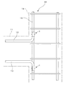
12 梁の上端筋(鉄筋)
13 梁の下端筋(鉄筋)
15 柱の主筋(鉄筋)
41 スターラップ筋(鉄筋)
43 床版の下端筋(鉄筋)
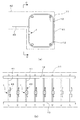
54a,54b 半円筒状部材
55a,55b 楔挿通孔
56a,56b 平板部
Claims (2)
- 接合対象である2本の鉄筋を並列状態で抱き込むことができるようにかつ一方の縁部が他方の縁部に重なるように湾曲形成され前記一方の縁部に第1の楔挿通孔が形成され該第1の楔挿通孔と同芯になるように前記他方の縁部に第2の楔挿通孔が形成され前記第1の楔挿通孔及び前記第2の楔挿通孔と同芯になるように前記一方の縁部及び前記他方の縁部の対向位置に第3の楔挿通孔が形成された開断面の鋼製筒状体と、前記第1の楔挿通孔、前記第2の楔挿通孔及び前記第3の楔挿通孔に挿通され前記2本の鉄筋の間に圧入される楔部材とから構成したことを特徴とする鉄筋継手具。
- U字状断面をなすとともに対向する各平板部に楔挿通孔が同芯に形成され相互に嵌め入れることが可能な一対の半円筒状部材と、接合対象である2本の鉄筋を並列状態で抱き込むようにして前記一対の半円筒状部材を相互に嵌め入れたとき、前記半円筒状部材にそれぞれ形成された2組の楔挿通孔に挿通され前記2本の鉄筋の間に圧入される楔部材とから構成したことを特徴とする鉄筋継手具。
Priority Applications (1)
| Application Number | Priority Date | Filing Date | Title |
|---|---|---|---|
| JP2007338998A JP4992143B2 (ja) | 2007-12-28 | 2007-12-28 | 鉄筋継手具 |
Applications Claiming Priority (1)
| Application Number | Priority Date | Filing Date | Title |
|---|---|---|---|
| JP2007338998A JP4992143B2 (ja) | 2007-12-28 | 2007-12-28 | 鉄筋継手具 |
Publications (2)
| Publication Number | Publication Date |
|---|---|
| JP2009161902A true JP2009161902A (ja) | 2009-07-23 |
| JP4992143B2 JP4992143B2 (ja) | 2012-08-08 |
Family
ID=40964825
Family Applications (1)
| Application Number | Title | Priority Date | Filing Date |
|---|---|---|---|
| JP2007338998A Active JP4992143B2 (ja) | 2007-12-28 | 2007-12-28 | 鉄筋継手具 |
Country Status (1)
| Country | Link |
|---|---|
| JP (1) | JP4992143B2 (ja) |
Citations (3)
| Publication number | Priority date | Publication date | Assignee | Title |
|---|---|---|---|---|
| JPS57190855A (en) * | 1981-05-15 | 1982-11-24 | Shinpachi Hamada | Joining of iron wire reinforcing concrete block |
| JPS5864727U (ja) * | 1981-10-26 | 1983-05-02 | 清水建設株式会社 | 鉄筋継手部構造 |
| JPS6082019U (ja) * | 1983-11-11 | 1985-06-06 | 鹿島建設株式会社 | 鉄筋用継手 |
-
2007
- 2007-12-28 JP JP2007338998A patent/JP4992143B2/ja active Active
Patent Citations (3)
| Publication number | Priority date | Publication date | Assignee | Title |
|---|---|---|---|---|
| JPS57190855A (en) * | 1981-05-15 | 1982-11-24 | Shinpachi Hamada | Joining of iron wire reinforcing concrete block |
| JPS5864727U (ja) * | 1981-10-26 | 1983-05-02 | 清水建設株式会社 | 鉄筋継手部構造 |
| JPS6082019U (ja) * | 1983-11-11 | 1985-06-06 | 鹿島建設株式会社 | 鉄筋用継手 |
Also Published As
| Publication number | Publication date |
|---|---|
| JP4992143B2 (ja) | 2012-08-08 |
Similar Documents
| Publication | Publication Date | Title |
|---|---|---|
| JP5080475B2 (ja) | 鉄筋の接合具 | |
| US20100088995A1 (en) | Reinforcing bar joint | |
| JP5035984B2 (ja) | プレキャスト床版と梁との接合構造 | |
| JP2015214807A (ja) | 異種鉄骨梁接合構造 | |
| JP4992143B2 (ja) | 鉄筋継手具 | |
| JP5051766B2 (ja) | プレキャスト床版と梁との接合構造 | |
| JP6314415B2 (ja) | 合成セグメントおよび合成セグメントの製造方法 | |
| JP2012117328A (ja) | 鋼板コンクリート構造の構造部材 | |
| KR101690995B1 (ko) | 충전강관 트러스 부재 및 충전강관 트러스 구조물 | |
| JP4455702B2 (ja) | 継手具及びその連結方法 | |
| JP2010047968A (ja) | 鋼殻とrc部材との接合構造 | |
| KR101147543B1 (ko) | 철근 커플러 | |
| JP5565925B2 (ja) | 鉄筋の接合構造 | |
| JP4350121B2 (ja) | 鉄筋の溶接式柱梁接合部定着構造 | |
| KR101116703B1 (ko) | 철근 커플러 | |
| JP2006322229A (ja) | ナット付き鋼矢板及びその施工方法 | |
| JP5355041B2 (ja) | 梁端プレキャストコンクリート造鉄骨梁 | |
| JP2006322230A (ja) | 鋼材付き鋼矢板及びその施工方法 | |
| JP2009013733A (ja) | カプラー使用による突合せ式重ね継手工法と突合せ式重ね継手 | |
| JP4565336B2 (ja) | 構造体および構造体の構築工法 | |
| KR102360387B1 (ko) | Cft용 강관 구조체 제작 방법 | |
| JP2002356923A (ja) | コンクリート充填筒状体の継手構造 | |
| JP4457350B2 (ja) | Src構造及びその構築方法 | |
| JP4075623B2 (ja) | 鋼管の接合構造及び接合方法 | |
| JP2006104785A (ja) | 定着部付き鉄筋 |
Legal Events
| Date | Code | Title | Description |
|---|---|---|---|
| A621 | Written request for application examination |
Free format text: JAPANESE INTERMEDIATE CODE: A621 Effective date: 20101108 |
|
| A977 | Report on retrieval |
Free format text: JAPANESE INTERMEDIATE CODE: A971007 Effective date: 20111222 |
|
| A131 | Notification of reasons for refusal |
Free format text: JAPANESE INTERMEDIATE CODE: A131 Effective date: 20120105 |
|
| TRDD | Decision of grant or rejection written | ||
| A01 | Written decision to grant a patent or to grant a registration (utility model) |
Free format text: JAPANESE INTERMEDIATE CODE: A01 Effective date: 20120417 |
|
| A01 | Written decision to grant a patent or to grant a registration (utility model) |
Free format text: JAPANESE INTERMEDIATE CODE: A01 |
|
| A61 | First payment of annual fees (during grant procedure) |
Free format text: JAPANESE INTERMEDIATE CODE: A61 Effective date: 20120419 |
|
| FPAY | Renewal fee payment (event date is renewal date of database) |
Free format text: PAYMENT UNTIL: 20150518 Year of fee payment: 3 |
|
| R150 | Certificate of patent or registration of utility model |
Free format text: JAPANESE INTERMEDIATE CODE: R150 Ref document number: 4992143 Country of ref document: JP Free format text: JAPANESE INTERMEDIATE CODE: R150 |