JP2009190884A - Lighting equipment for passenger conveyors - Google Patents
Lighting equipment for passenger conveyors Download PDFInfo
- Publication number
- JP2009190884A JP2009190884A JP2008036022A JP2008036022A JP2009190884A JP 2009190884 A JP2009190884 A JP 2009190884A JP 2008036022 A JP2008036022 A JP 2008036022A JP 2008036022 A JP2008036022 A JP 2008036022A JP 2009190884 A JP2009190884 A JP 2009190884A
- Authority
- JP
- Japan
- Prior art keywords
- light source
- source unit
- led light
- passenger conveyor
- guide plate
- Prior art date
- Legal status (The legal status is an assumption and is not a legal conclusion. Google has not performed a legal analysis and makes no representation as to the accuracy of the status listed.)
- Pending
Links
Images

Landscapes
- Escalators And Moving Walkways (AREA)
Abstract
【課題】トリガ信号に応じて、発光状態を自在に制御することができる乗客コンベアの照明装置の提供。
【解決手段】乗客コンベアの欄干に配設され、乗降口、及び踏段を照らす乗客コンベアの照明装置において、LED光源部と、このLED光源部に電源を供給する電源回路9と、LED光源部と電源回路9との間に設けられ、トリガ信号を受けてLED光源部を制御する制御回路10とを備えた。制御回路10は、トリガ信号に応じて、LED光源部の点滅回数や点滅周期、LED照度の増減、及び発光色を制御可能になっている。LED光源部は、例えば1個の発光素子6と、導光板7とから成り、導光板7の片端に発光素子6を設けた構成にしてある。
【選択図】図1Provided is a passenger conveyor lighting device capable of freely controlling a light emission state in accordance with a trigger signal.
In a lighting device for a passenger conveyor that is disposed on a railing of a passenger conveyor and illuminates a boarding / exit and a step, an LED light source unit, a power supply circuit 9 that supplies power to the LED light source unit, and an LED light source unit, A control circuit 10 is provided between the power source circuit 9 and the LED light source unit in response to a trigger signal. The control circuit 10 can control the number of blinks and blinking cycle of the LED light source unit, increase / decrease in LED illuminance, and emission color in accordance with the trigger signal. The LED light source unit includes, for example, one light-emitting element 6 and a light guide plate 7, and the light-emitting element 6 is provided at one end of the light guide plate 7.
[Selection] Figure 1
Description
本発明は、乗客コンベアの欄干部に配設され、乗降口、及び踏段を照らす乗客コンベアの照明装置に関する。 The present invention relates to an illumination device for a passenger conveyor that is disposed in a railing portion of a passenger conveyor and illuminates a boarding / exit gate and a step.
この種の従来技術として、特許文献1に示されるものがある。この従来の乗客コンベアの照明装置は、乗客検出信号を捉えて、乗客コンベアを起動、停止させる制御装置のトリガ信号と同期させて、一定期間乗客を検知しないと照明装置の照度を減少させ、ランプ寿命を延ばそうとするものである。
上述した従来の乗客コンベアの照明装置は、光源に蛍光灯を用いており、制御回路によって照度の増減を実現させることは困難であった。また、蛍光灯の点滅を行なうとランプの寿命が短くなってしまう問題があった。このように従来技術は、発光状態の制御に制約を受けやすかった。 The above-described conventional illumination device for passenger conveyors uses a fluorescent lamp as a light source, and it has been difficult to realize increase / decrease in illuminance by a control circuit. Further, when the fluorescent lamp is blinked, there is a problem that the life of the lamp is shortened. As described above, the conventional technology is easily restricted by the control of the light emission state.
本発明は、前述した従来技術における実状からなされたもので、その目的は、トリガ信号に応じて、発光状態を自在に制御することができる乗客コンベアの照明装置を提供することにある。 The present invention has been made from the above-described prior art, and an object thereof is to provide an illumination device for a passenger conveyor that can freely control the light emission state in accordance with a trigger signal.
前記目的を達成するために、本発明に係る乗客コンベアの照明装置は、乗客コンベアの欄干部に配設され、乗降口、及び踏段を照らす乗客コンベアの照明装置において、LED光源部と、このLED光源部に電源を供給する電源回路と、前記LED光源部と前記電源回路との間に設けられ、トリガ信号を受けて前記LED光源部を制御する制御回路とを備えたことを特徴としている。 In order to achieve the above object, a lighting device for a passenger conveyor according to the present invention is disposed in a railing portion of a passenger conveyor and illuminates an entrance / exit and a step. A power supply circuit that supplies power to the light source unit, and a control circuit that is provided between the LED light source unit and the power supply circuit and controls the LED light source unit in response to a trigger signal are provided.
また、本発明に係る乗客コンベアの照明装置は、前記発明において、前記制御回路は、前記トリガ信号に応じて、前記LED光源部の点滅回数や点滅周期、LED照度の増減、及び発光色を制御可能であることを特徴としている。 In the passenger conveyor lighting device according to the present invention, in the invention, the control circuit controls the number of blinks and the blink cycle of the LED light source unit, increase / decrease in LED illuminance, and emission color according to the trigger signal. It is characterized by being possible.
また、本発明に係る乗客コンベアの照明装置は、前記発明において、前記LED光源部は、複数個の発光素子と、導光板とから成り、前記導光板の片端若しくは両端に、複数個の前記発光素子を設けたことを特徴としている。 In the illumination device for a passenger conveyor according to the present invention, in the invention, the LED light source unit includes a plurality of light emitting elements and a light guide plate, and a plurality of the light emitting elements are provided at one or both ends of the light guide plate. An element is provided.
また、本発明に係る乗客コンベアの照明装置は、前記発明において、前記LED光源部は、少なくとも2色の発光が可能な前記発光素子を含むことを特徴としている。 In the passenger conveyor lighting device according to the present invention, the LED light source unit includes the light emitting element capable of emitting at least two colors.
本発明によれば、従来の照明装置では困難であったトリガ信号に応じて、発光状態を自在に制御することが可能となり、従来に比べて照明機能を向上させることができる。また、消費電力を抑制することが可能となり、これにより経済性を向上させることができ、また装置の長寿命化を実現させることができる。 ADVANTAGE OF THE INVENTION According to this invention, it becomes possible to control a light emission state freely according to the trigger signal which was difficult with the conventional illuminating device, and an illumination function can be improved compared with the past. In addition, it is possible to suppress power consumption, thereby improving economic efficiency and extending the life of the apparatus.
以下、本発明の乗客コンベアの照明装置に関する実施形態を図に基づいて説明する。 DESCRIPTION OF EMBODIMENTS Hereinafter, embodiments relating to a passenger conveyor lighting device of the present invention will be described with reference to the drawings.
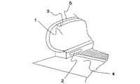
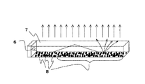
図1は本発明の乗客コンベアの照明装置の一実施形態を示す構成図、図2は本実施形態を乗客コンベアに取り付けた状態を示す斜視図、図3は本実施形態に備えられるLED光源部の一例を示す斜視図である。 FIG. 1 is a block diagram showing an embodiment of a lighting device for a passenger conveyor of the present invention, FIG. 2 is a perspective view showing a state in which the embodiment is attached to a passenger conveyor, and FIG. 3 is an LED light source unit provided in the embodiment. It is a perspective view which shows an example.
図2に示すように、本実施形態に係る照明装置2,3は、欄干1の下部の乗降口4付近や、移動手摺5の下部に配置される。これらの照明装置2,3に備えられるLED光源部は、図3に示すように、発光素子6と、導光板7と、この導光板7に貼付若しくは刻印した反射ドット8とから構成されている。発光素子6は、例えば導光板7の片端に1個設けてある。発光素子6から出た光は、導光板7の側面部から入射され、導光板7に入射された光は、導光板7内において反射を繰り返しながら広がる。この際に、反射ドット8に光が当たると、そこで光が散乱し、導光板7の表面から光が放射される。
As shown in FIG. 2, the
本実施形態は、図1に示すように、反射ドット8を有する導光板7、及び発光素子6から成るLED光源部と、このLED光源部に電源を供給する電源回路9との間に制御回路10を設けてあり、この制御回路10に入力されるトリガ信号11に応じてLED光源部が制御されるようになっている。例えば制御回路10によって、LED電源部の点滅回数や点滅周期、LED照度の増減、及び発光色が制御可能になっている。
In the present embodiment, as shown in FIG. 1, a control circuit is provided between an LED light source unit including a
なお、電源回路9には、図示しないコンセントに接続される電気プラグ12が付設されている。また、発光素子6と導光板7とから成るLED光源部は、乗客コンベアの欄干1部分に取り付けられる窓13に対向するように配置させてある。LED光源部の光は、窓13を通して乗降口4及び踏段を照らすようになっている。
The power supply circuit 9 is provided with an
このように構成した本実施形態に係る照明装置2,3は、図1に示すトリガ信号、例えば乗客コンベアへの乗客の乗り込み検知信号に応じて、制御回路10が、LED光源部の発光素子6の点滅回数や点滅周期、照度の増減、及び発光色を制御可能であるので、LED光源部の発光状態を自在に制御することができ、照明機能を向上させることができる。また、消費電力を抑制することが可能になり、これにより経済性を向上させることができ、また装置の長寿命化を実現させることができる。
The
なお、図3に示すLED光源部は、1個の発生素子6を導光板7の片端に設けた構成にしてあるが、導光板7の他の片端にも別の1個の発光素子6を設けた構成にしてもよい。
The LED light source unit shown in FIG. 3 has a configuration in which one generating
なお、トリガ信号として、故障検知信号や、いたずら検知信号を選定し、これらのトリガ信号に関連づけて点滅回数や点滅周期、照度の増減、及び発光色を予め設定しておけば、本実施形態の照明装置2,3の点灯状態を見るだけで、故障状況や、いたずらの種類を容易に把握することができ、保全の簡易化を実現させることができる。
In addition, if a failure detection signal or a tampering detection signal is selected as a trigger signal, and the number of blinks, blink period, increase / decrease in illuminance, and emission color are set in advance in association with these trigger signals, the present embodiment By simply looking at the lighting state of the
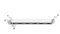
図4は本実施形態に備えられるLED光源部の他の例を示す斜視図である。この図4に示すLED光源部は、導光板7の両端に複数個の発光素子6を設けてある。発光素子6は、少なくとも2色のものから構成されている。例えば、この図4に示す発光素子6は、赤、青、緑の光の3原色の発光が可能になっている。
FIG. 4 is a perspective view showing another example of the LED light source unit provided in the present embodiment. The LED light source unit shown in FIG. 4 is provided with a plurality of
この図4に示すようにLED光源部を構成したものは、制御回路10によって発光素子6の点灯数を制御することにより照度の増減を制御できる。また、発光素子6の各発光色の発光強度と、発光タイミングとを組み合わせて発光させることで、様々な発色が可能となり、意匠性を向上させることができる。また、注意喚起機能を向上させることができ、これによって優れた安全性の確保に貢献する。
As shown in FIG. 4, the LED light source unit can be configured to control increase / decrease in illuminance by controlling the number of lighting of the
なお、図4に示すLED光源部は、複数の発光素子6を導光板6の両端に設けた構成にしてあるが、複数の発光素子6を片端のみに設けた構成にしてもよい。
The LED light source unit shown in FIG. 4 has a configuration in which a plurality of
1 欄干
2 照明装置
3 照明装置
4 乗降口
5 移動手摺
6 発光素子
7 導光板
8 反射ドット
9 電源回路
10 制御回路
11 トリガ信号
12 電気プラグ
13 窓
DESCRIPTION OF
Claims (4)
LED光源部と、このLED光源部に電源を供給する電源回路と、前記LED光源部と前記電源回路との間に設けられ、トリガ信号を受けて前記LED光源部を制御する制御回路とを備えたことを特徴とする乗客コンベアの照明装置。 In the passenger conveyor lighting device, which is disposed in the railing of the passenger conveyor, illuminates the entrance and exit, and the steps,
An LED light source unit, a power circuit that supplies power to the LED light source unit, and a control circuit that is provided between the LED light source unit and the power circuit and that controls the LED light source unit upon receiving a trigger signal A passenger conveyor lighting device characterized by the above.
前記制御回路は、前記トリガ信号に応じて、前記LED光源部の点滅回数や点滅周期、LED照度の増減、及び発光色を制御可能であることを特徴とする乗客コンベアの照明装置。 In the illumination device for a passenger conveyor according to claim 1,
The said control circuit can control the blink frequency | count and blink period of the said LED light source part, increase / decrease in LED illumination intensity, and luminescent color according to the said trigger signal, The illuminating device of the passenger conveyor characterized by the above-mentioned.
前記LED光源部は、複数個の発光素子と、導光板とから成り、前記導光板の片端若しくは両端に、複数個の前記発光素子を設けたことを特徴とする乗客コンベアの照明装置。 In the illumination device for a passenger conveyor according to claim 1,
The LED light source unit includes a plurality of light emitting elements and a light guide plate, and the light guide plate is provided with a plurality of light emitting elements at one or both ends of the light guide plate.
前記LED光源部は、少なくとも2色の発光が可能な前記発光素子を含むことを特徴とする乗客コンベアの照明装置。 In the illumination device for passenger conveyor according to claim 3,
The LED light source unit includes the light emitting element capable of emitting at least two colors, and the illumination device for a passenger conveyor.
Priority Applications (1)
| Application Number | Priority Date | Filing Date | Title |
|---|---|---|---|
| JP2008036022A JP2009190884A (en) | 2008-02-18 | 2008-02-18 | Lighting equipment for passenger conveyors |
Applications Claiming Priority (1)
| Application Number | Priority Date | Filing Date | Title |
|---|---|---|---|
| JP2008036022A JP2009190884A (en) | 2008-02-18 | 2008-02-18 | Lighting equipment for passenger conveyors |
Publications (1)
| Publication Number | Publication Date |
|---|---|
| JP2009190884A true JP2009190884A (en) | 2009-08-27 |
Family
ID=41073242
Family Applications (1)
| Application Number | Title | Priority Date | Filing Date |
|---|---|---|---|
| JP2008036022A Pending JP2009190884A (en) | 2008-02-18 | 2008-02-18 | Lighting equipment for passenger conveyors |
Country Status (1)
| Country | Link |
|---|---|
| JP (1) | JP2009190884A (en) |
Cited By (4)
| Publication number | Priority date | Publication date | Assignee | Title |
|---|---|---|---|---|
| JP2013129498A (en) * | 2011-12-21 | 2013-07-04 | Hitachi Ltd | Passenger conveyor system, and method for illuminating and controlling the same |
| JP2016172618A (en) * | 2015-03-17 | 2016-09-29 | 株式会社日立製作所 | Passenger conveyor |
| JP2023011112A (en) * | 2021-07-12 | 2023-01-24 | 三菱電機ビルソリューションズ株式会社 | Passenger Conveyor Balustrade Lighting System |
| JP7529115B1 (en) | 2023-09-21 | 2024-08-06 | フジテック株式会社 | Man Conveyor |
-
2008
- 2008-02-18 JP JP2008036022A patent/JP2009190884A/en active Pending
Cited By (6)
| Publication number | Priority date | Publication date | Assignee | Title |
|---|---|---|---|---|
| JP2013129498A (en) * | 2011-12-21 | 2013-07-04 | Hitachi Ltd | Passenger conveyor system, and method for illuminating and controlling the same |
| JP2016172618A (en) * | 2015-03-17 | 2016-09-29 | 株式会社日立製作所 | Passenger conveyor |
| JP2023011112A (en) * | 2021-07-12 | 2023-01-24 | 三菱電機ビルソリューションズ株式会社 | Passenger Conveyor Balustrade Lighting System |
| JP7716915B2 (en) | 2021-07-12 | 2025-08-01 | 三菱電機ビルソリューションズ株式会社 | Passenger conveyor railing lighting equipment |
| JP7529115B1 (en) | 2023-09-21 | 2024-08-06 | フジテック株式会社 | Man Conveyor |
| JP2025047172A (en) * | 2023-09-21 | 2025-04-03 | フジテック株式会社 | Man Conveyor |
Similar Documents
| Publication | Publication Date | Title |
|---|---|---|
| EP1103759A3 (en) | Full-color light source unit | |
| WO2007035203A3 (en) | Power controls with photosensor for tube mounted leds with ballast | |
| EP2903012A1 (en) | Switch | |
| WO2009150085A3 (en) | Escalator or moving walkway with led illumination | |
| CN106662316B (en) | Luminous body and method for presence detection by means of such a luminous body | |
| JP2017149511A (en) | Passenger conveyor | |
| US20080304253A1 (en) | Lighted handrail | |
| JP2011051706A (en) | Lighting system for passenger conveyor | |
| KR101055177B1 (en) | LED lighting device | |
| JP2004203619A (en) | Escalator | |
| KR101055176B1 (en) | LED lighting device | |
| JP4103055B2 (en) | Handrail lighting device | |
| TW200946823A (en) | Support plate for light-emitting points and related facade system | |
| US9127815B2 (en) | Lighting apparatus | |
| JP2007284168A (en) | Railing lighting device for passenger conveyor | |
| WO2000013164A1 (en) | Display | |
| KR101069694B1 (en) | Multi-post operation escalator and maving walk head sensor turn round an angle reguiation | |
| JP2006321585A (en) | Passenger conveyor | |
| CN105984797A (en) | Passenger conveyor | |
| JP2008122045A (en) | Air conditioner display device | |
| KR200442866Y1 (en) | Light emitting device for getting off the bus | |
| CN219408831U (en) | Guiding device and passenger conveyor | |
| KR101688406B1 (en) | Pattern luminescence led signal lamp | |
| JP2007049550A (en) | Proximity switch device and lighting control system | |
| KR200464778Y1 (en) | Lighting guide apparatus of escalator floor plate |