JP2009262003A - Grinding machine and equipment for manufacturing toner - Google Patents
Grinding machine and equipment for manufacturing toner Download PDFInfo
- Publication number
- JP2009262003A JP2009262003A JP2008111363A JP2008111363A JP2009262003A JP 2009262003 A JP2009262003 A JP 2009262003A JP 2008111363 A JP2008111363 A JP 2008111363A JP 2008111363 A JP2008111363 A JP 2008111363A JP 2009262003 A JP2009262003 A JP 2009262003A
- Authority
- JP
- Japan
- Prior art keywords
- rotor
- stator
- toner
- pulverized
- convex portions
- Prior art date
- Legal status (The legal status is an assumption and is not a legal conclusion. Google has not performed a legal analysis and makes no representation as to the accuracy of the status listed.)
- Pending
Links
Images




Landscapes
- Developing Agents For Electrophotography (AREA)
- Crushing And Grinding (AREA)
- Crushing And Pulverization Processes (AREA)
Abstract
【課題】回転子及び固定子を内蔵する粉砕機において、重量平均粒径6μm以下の小粒径で、且つ、微粉体の少ないシャープな粒度分布を有するトナー粒子を、効率良く、安定的に、トナー生産性良く得ることができる粉砕機を提供することである。
【解決手段】回転子及び固定子を内蔵する粉砕機において、回転子314及び固定子310表面の凹凸部が、中心回転軸312に対して平行に設けられており、回転子314は内部に冷却用の冷媒流路を特定の条件で具備し、回転子314と固定子310表面の凹凸部距離が粉砕ゾーンにより異なり、回転子314表面の凹凸部距離が粉砕ゾーンにより異なる。
【選択図】図1In a pulverizer having a built-in rotor and stator, toner particles having a small particle size with a weight average particle size of 6 μm or less and a sharp particle size distribution with few fine powders can be efficiently and stably produced. An object of the present invention is to provide a pulverizer that can be obtained with good toner productivity.
In a pulverizer having a built-in rotor and stator, uneven portions on the surfaces of the rotor 314 and the stator 310 are provided in parallel to the central rotation shaft 312 and the rotor 314 is cooled inside. The coolant flow path for the surface of the rotor 314 and the surface of the stator 310 is different depending on the grinding zone, and the distance of the unevenness on the surface of the rotor 314 is different depending on the grinding zone.
[Selection] Figure 1
Description
本発明は、電子写真法、静電記録法、静電印刷法、またはトナージェット方式記録法の如き画像形成方法に用いられるトナーを製造する装置及びその装置を利用してトナーを製造する方法に関する。 The present invention relates to an apparatus for producing toner used in an image forming method such as an electrophotographic method, an electrostatic recording method, an electrostatic printing method, or a toner jet recording method, and a method for producing toner using the device. .
電子写真法、静電写真法及び静電印刷法の如き画像形成方法では、静電荷像を現像するためのトナーが使用される。 In image forming methods such as electrophotography, electrostatic photography, and electrostatic printing, toner for developing an electrostatic charge image is used.
トナーを製造する方法の一つに以下の方法がある。 One of the methods for producing toner is the following method.
まず、被転写材に定着させるための結着樹脂、トナーとしての色味を出させる各種着色剤、粒子に電荷を付与させるための荷電制御剤を原料とし、更に必要に応じて、例えば、離型剤及び流動性付与剤等の他の添加剤を加えて乾式混合を行う。 First, a binder resin for fixing to a transfer material, various colorants for producing a color as a toner, and a charge control agent for imparting electric charge to particles are used as raw materials. Other additives such as a mold and a fluidity-imparting agent are added and dry mixing is performed.
しかる後、ロールミル、エクストルーダー等の汎用混練装置にて溶融混練し、冷却固化した後、混練物を各種粉砕装置により微細化し、得られた粉砕物を各種風力分級機に導入して分級を行うことにより、トナーとして必要な粒径に揃えられた分級品を得る。 After that, after melt-kneading with a general-purpose kneading device such as a roll mill or an extruder and cooling and solidifying, the kneaded material is refined with various pulverizing devices, and the obtained pulverized material is introduced into various air classifiers for classification. As a result, a classified product having a particle size required for the toner is obtained.
更に、得られた分級品に、必要に応じて、流動化剤や滑剤等を外添し、乾式混合して、画像形成に供するトナーとしている。 Furthermore, if necessary, a fluidizing agent or a lubricant is externally added to the obtained classified product, and dry-mixed to obtain a toner for image formation.
また、二成分現像方法に用いるトナーの場合には、各種磁性キャリアと上記トナーとを混ぜ合わせた後、画像形成に供される。 In the case of a toner used in the two-component development method, various magnetic carriers and the above toner are mixed and then used for image formation.
近年、複写機やプリンターの高画質化・高精細化に伴い、現像剤としてのトナーに要求される性能も一段と厳しくなっており、トナーとしては、粒子径は小さく(具体的には、重量平均粒径6μm以下)、粒度分布としては、粗大な粒子が含有されず、且つ、微粉体の少ないシャープなものが必要とされている。 In recent years, with higher image quality and higher definition of copiers and printers, the performance required of toner as a developer has become more severe, and the toner has a smaller particle size (specifically, weight average) As the particle size distribution, there is a need for sharp particles which do not contain coarse particles and have few fine powders.
上述した重量平均粒径6μm以下のトナー粒子を得るために、従来、粉砕手段としては、図11に示す粉砕機が用いられることが多い。 In order to obtain the above-described toner particles having a weight average particle size of 6 μm or less, a pulverizer shown in FIG.
図11に示す粉砕機は、ジェット気流の如き高圧気体で粉体原料を搬送し、加速管の出口より噴射し、加速管の出口の開口面に対向して設けた衝突部材の衝突面に衝突させて、その衝撃力により粉体原料を粉砕する。 The pulverizer shown in FIG. 11 conveys the powder raw material with a high-pressure gas such as a jet stream, injects it from the outlet of the acceleration tube, and collides with the collision surface of the collision member provided facing the opening surface of the acceleration tube outlet. The powder raw material is pulverized by the impact force.
例えば、図11に示す粉砕機では、高圧気体供給ノズル435を接続した加速管出口に対向して衝突部材436を設け、加速管に供給した高圧気体により、加速管の中途に連通させた粉体原料供給口から加速管内に粉体原料を吸引し、粉体原料を高圧気体とともに噴出して衝突部材436の衝突面に衝突させ、その衝撃によって粉砕し、粉砕物を粉砕物排出口より排出させている。
For example, in the pulverizer shown in FIG. 11, a
図11に示す粉砕機は、粉体原料を高圧気体とともに噴出して衝突部材436の衝突面に衝突させ、その衝撃によって粉砕するという構成のため、重量平均粒径6μm以下の小粒径のトナー粒子を得ることは可能である。
The pulverizer shown in FIG. 11 has a configuration in which the powder raw material is jetted together with high-pressure gas, collides with the collision surface of the
しかしながら、図11に示す粉砕機で、重量平均粒径6μm以下の小粒径トナー粒子を生産するためには多量のエアーを必要とする。そのため電力消費が極めて多く、エネルギーコストという面において問題を抱えている。 However, a large amount of air is required in order to produce toner particles having a weight average particle diameter of 6 μm or less with the pulverizer shown in FIG. Therefore, power consumption is extremely large, and there is a problem in terms of energy cost.
また、重量平均粒径6μm以下のトナー粒子を得ようとして、図11に示す粉砕機で粉砕すると、発生する微粉量が多くなり、後工程の分級工程において分級収率の低下を招き、トナー生産性上好ましくない。 Further, if toner particles having a weight average particle diameter of 6 μm or less are obtained and pulverized by the pulverizer shown in FIG. 11, the amount of fine powder generated increases, resulting in a decrease in classification yield in the subsequent classification process, and toner production. It is not preferable in nature.
これに対し、エネルギー的に図11に示す粉砕機より効率的な粉砕機として、図1に示す粉砕機が用いられている。 On the other hand, the pulverizer shown in FIG. 1 is used as a pulverizer that is energetically more efficient than the pulverizer shown in FIG.
例えば、図1に示す粉砕機では、定量供給機315から粉砕機の原料投入口311へ所定量の粉体原料が投入されると、原料は粉砕処理室内に導入され、該粉砕処理室内で高速回転する表面に多数の溝が設けられている回転子314と、表面に多数の溝が設けられている固定子310との間に発生する衝撃と、この背後に生じる多数の超高速渦流、並びにこれによって発生する高周波の圧力振動によって瞬間的に粉砕される。
For example, in the pulverizer shown in FIG. 1, when a predetermined amount of powder raw material is introduced from the
上述した通り、図1に示す粉砕機は、高速回転する回転子314と、回転子の周囲に配置されている固定子310との間に形成された環状空間である粉砕ゾーンに粉体原料を導入することにより粉砕する。従って、粉砕の際、多量のエアーを必要としない。
As described above, the pulverizer shown in FIG. 1 applies the powder raw material to the pulverization zone which is an annular space formed between the
そのため電力消費が極めて少なくてすみ、図11に示す粉砕機より格段に省エネルギーで粉砕できる。しかも過粉砕されることが少ないため微粉の発生が少なく、後工程の分級工程において分級収率を向上させることが可能となる。 Therefore, power consumption is extremely small, and the pulverization can be performed with much less energy than the pulverizer shown in FIG. Moreover, since it is rarely excessively pulverized, the generation of fine powder is small, and it is possible to improve the classification yield in the subsequent classification process.
またこれらの粉砕機によって粉砕されたトナー粒子の形状に着目すると、図11に示す粉砕機で粉砕されたトナー粒子は不定形で角張った形状であり、図1に示す粉砕機で粉砕されたトナー粒子は角が取れ、丸みを有する形状であることが知られている。 Focusing on the shape of the toner particles pulverized by these pulverizers, the toner particles pulverized by the pulverizer shown in FIG. 11 have an irregular and square shape, and the toner pulverized by the pulverizer shown in FIG. It is known that the particles are rounded and rounded.
粉砕されたトナー粒子の形状の差は粉砕プロセスの相違によるものと考えられる。即ち、図11に示す粉砕機においては、大部分の粉砕は、衝突部材との衝突によって行われるが、図1に示す粉砕機においては、大部分の粉砕は高速回転する回転子314及び固定子310の壁面に粒子が衝突して行われるためである。
The difference in the shape of the pulverized toner particles is considered to be due to the difference in the pulverization process. That is, in the pulverizer shown in FIG. 11, most of the pulverization is performed by collision with the collision member, but in the pulverizer shown in FIG. 1, most of the pulverization is performed by the
また、図1に示す粉砕機においては、少なからず粉砕によって発熱が生じ、熱球形化による効果もあって、粉砕されたトナー粒子の形状は丸みを帯びるとも考えられる。 Further, in the pulverizer shown in FIG. 1, it is considered that heat is generated by pulverization, and the shape of the pulverized toner particles is rounded due to the effect of thermal spheroidization.
このため、図1に示す粉砕機で粉砕されたトナー粒子は、図11に示す粉砕機で粉砕されたトナー粒子より比表面積が小さくなるため、流動性が良好になり、また空隙が小さくなるため、充填性に優れ、更に外添剤の添加量が少量で済むというメリットがある。 For this reason, the toner particles pulverized by the pulverizer shown in FIG. 1 have a smaller specific surface area than the toner particles pulverized by the pulverizer shown in FIG. Further, there is an advantage that the filling property is excellent and the addition amount of the external additive is small.
また、帯電性や転写性に優れるなど品質面のメリットも挙げられる。即ち、図1に示す粉砕機によれば、優れた品質のトナーを省エネルギー且つ高収率で生産することができる。 In addition, there are merits in quality such as excellent chargeability and transferability. In other words, according to the pulverizer shown in FIG. 1, it is possible to produce toner of excellent quality with energy saving and high yield.
しかしながら、図1に示す粉砕機は、高速回転する回転子314と、回転子314の周囲に配置されている固定子310との間に形成された粉砕ゾーンに粉体原料を導入することにより粉砕するという構成のため、トナー粒子径を決める因子の大部分は、回転子314の回転数と、回転子314と固定子310の最小間隔で決まると考えられる。
However, the pulverizer shown in FIG. 1 is pulverized by introducing a powder raw material into a pulverization zone formed between a
そのため、図1に示す粉砕機で、重量平均粒径6μm以下の小粒径のトナー粒子を得ようとすると、回転子314の高速化及び回転子314と固定子310の最小間隔の狭化が必要となる。
Therefore, if the pulverizer shown in FIG. 1 is used to obtain toner particles having a small particle diameter of 6 μm or less, the speed of the
しかしながら、回転子314の回転数や、回転子314と固定子310の最小間隔は装置構成上おのずと限界点があり、そのため図1に示す粉砕機において、重量平均粒径6μm以下の小粒径のトナー粒子を得るのは非常に困難であった。
However, the number of rotations of the
図1に示す粉砕機において小粒径のトナー粒子を得る方法として、回転子314及び固定子310の少なくとも一方の表面において、当該表面の多数の溝の繰り返し周期を異ならせた粉砕機が提案されている(例えば、特許文献1参照)。
As a method for obtaining toner particles having a small particle size in the pulverizer shown in FIG. 1, a pulverizer is proposed in which at least one of the surfaces of the
また、表面に凹部と凸部を交互に周方向に連続させた回転子を2段以上に区画し、原料供給口側の最下段から製品排出口側の最上段に向かって凹部と凸部の数を順次増加した粉砕機が提案されている(例えば、特許文献2参照)。 Further, a rotor having recesses and protrusions alternately arranged in the circumferential direction on the surface is divided into two or more stages, and the recesses and protrusions are formed from the lowest stage on the raw material supply port side toward the uppermost stage on the product discharge port side. There has been proposed a pulverizer in which the number is sequentially increased (for example, see Patent Document 2).
しかしながら、いずれにおいても重量平均粒径6μm以下の小粒径のトナー粒子を得ることは可能ではあるものの、原料投入口から投入される粉体原料の所定量を低く設定しなければならず、トナー生産性との両立という点において未だ不十分であった。 However, although it is possible to obtain toner particles having a small particle diameter of 6 μm or less in any case, a predetermined amount of powder raw material charged from the raw material inlet must be set low, and the toner It was still insufficient in terms of compatibility with productivity.
また、CO2排出量削減への配慮から、小粒径で、且つ、シャープな粒度分布を有するトナー粒子を、低エネルギーで、効率良く、安定的に作り出すことが必要であり、更にトナー生産性を十分満足させることが必要である。 In consideration of reducing CO 2 emissions, it is necessary to produce toner particles with a small particle size and sharp particle size distribution with low energy, efficiently and stably. It is necessary to fully satisfy
本発明の目的は、こうした問題点を解消して、重量平均粒径6μm以下の小粒径で、且つ、微粉体の少ないシャープな粒度分布を有するトナー粒子を、効率良く、安定的に、トナー生産性良く得られる粉砕機を提供することにある。 An object of the present invention is to solve such problems and to efficiently and stably produce toner particles having a small particle diameter of 6 μm or less and a sharp particle size distribution with few fine powders. An object of the present invention is to provide a crusher that can be obtained with high productivity.
更に本発明の目的は、粉砕室内温度上昇による品質弊害や機内融着を防止でき、且つ、単位時間当りの処理量を向上させることができるトナー製造装置を提供することにある。 It is another object of the present invention to provide a toner manufacturing apparatus that can prevent adverse effects on quality due to temperature rise in the grinding chamber and in-machine fusion and can improve the throughput per unit time.
本発明者等は、上記した従来技術の課題を解決すべく鋭意検討の結果、図1に示す粉砕機に内蔵される回転子314外周面の歯の構成と、該回転子314の外周に設置されている固定子310内周面の歯の構成に着目し、本発明に至った。
As a result of intensive studies to solve the above-described problems of the prior art, the present inventors have established the teeth configuration on the outer peripheral surface of the
即ち、本発明は、被粉砕物を粉砕手段内に投入するための粉体投入口311と、固定子310と、少なくとも中心回転軸312に取り付けられた回転子314と、粉砕された粉体を粉砕手段から排出するための粉体排出口302とを少なくとも有し、
該固定子310は該回転子314を内包しており、
該固定子310表面と該回転子314表面とは、所定の間隙を有するように該回転子314は配置されて粉砕ゾーンを形成しており、
該粉砕ゾーンにおいて、該回転子314の回転に伴って被粉砕物が粉砕され、
該固定子310表面及び回転子314表面は、いずれも複数の凸部と凹部とを有する粉砕機において、
該凹凸部が、該中心回転軸312に対して平行に設けられており、
該回転子314は内部に冷却用の冷媒流路を具備し、
該回転子314表面の凸部と凸部との繰り返し距離をRa、
該固定子310表面の凸部と凸部との繰り返し距離をLaとしたとき、
該粉砕ゾーンにおいて、該Raと該Laが互いに異なる範囲が存在するよう、該回転子314及び固定子310表面の凸部と凸部との繰り返し距離を設定し、
該回転子314において、該Raが異なる範囲が存在するよう、該回転子314表面の凸部と凸部との繰り返し距離を設定することを特徴とする粉砕機に関する。
That is, according to the present invention, the
The
The
In the pulverization zone, the object to be crushed is pulverized as the
The surface of the
The concavo-convex portion is provided in parallel to the
The
The repetition distance between the convex portions on the surface of the
When the repetition distance between the convex portions on the surface of the
In the pulverization zone, the repetition distance between the convex portions and the convex portions on the surface of the
The present invention relates to a pulverizer characterized in that a repetition distance between a convex portion and a convex portion on the surface of the
本発明によれば、重量平均粒径6μm以下の小粒径で、且つ、微粉体の少ないシャープな粒度分布を有するトナー粒子を、効率良く、安定的に、トナー生産性良く得ることができる粉砕機を提供することができる。 According to the present invention, toner particles having a small particle diameter of 6 μm or less and a sharp particle size distribution with few fine powders can be obtained efficiently, stably, and with good toner productivity. Machine can be provided.
更に本発明によれば、粉砕室内温度上昇による品質弊害や機内融着を防止でき、且つ、単位時間当りの処理量を向上させることができるトナー製造装置を提供することができる。 Further, according to the present invention, it is possible to provide a toner manufacturing apparatus that can prevent adverse effects on quality due to an increase in the temperature in the pulverization chamber and in-machine fusion, and can improve the throughput per unit time.
更には、良好な現像性、転写性並びにクリーニング性、及び安定した帯電性を有する、長寿命のトナーを得ることができる。 Furthermore, a long-life toner having good developability, transferability, cleaning property, and stable chargeability can be obtained.
以下、好ましい実施の形態を挙げて本発明を更に詳細に説明する。 Hereinafter, the present invention will be described in more detail with reference to preferred embodiments.
本発明者は、上記した従来技術の課題を解決すべく、図1に示す粉砕機で、重量平均粒径6μm以下のトナー粒子を、単位時間当りの処理量がより高い状態で得るべく鋭意検討した結果、該回転子314表面の凸部と凸部との繰り返し距離と、該固定子310表面の凸部と凸部との繰り返し距離に着目した。
In order to solve the above-described problems of the prior art, the present inventor has intensively studied to obtain toner particles having a weight average particle diameter of 6 μm or less with a higher processing amount per unit time with the pulverizer shown in FIG. As a result, attention was paid to the repetition distance between the protrusions on the surface of the
つまり、図1に示す粉砕機おける粉砕性は、該回転子314の周速と、該回転子314と、該固定子310の最小間隔が最も影響していると考えられるが、それ以外にも該回転子314及び固定子310表面の凸部と凸部との繰り返し距離も影響していると考えた。
That is, it is considered that the grindability in the grinder shown in FIG. 1 is most influenced by the peripheral speed of the
本発明において上述した目的を達成するために好ましい装置の構成を、図1から図3を用いて説明する。 In order to achieve the above-described object in the present invention, a configuration of a preferable apparatus will be described with reference to FIGS.
図1は、本発明において使用される一例の粉砕機の概略的断面図であり、図2及び図3は、本発明において使用される一例の該回転子314及び固定子310の概略的断面図である。
FIG. 1 is a schematic cross-sectional view of an example crusher used in the present invention, and FIGS. 2 and 3 are schematic cross-sectional views of an example of the
本発明の粉砕機は、被粉砕物を粉砕手段内に投入するための粉体投入口311と、固定子310と、少なくとも中心回転軸312に取り付けられた回転子314と、粉砕された粉体を粉砕手段から排出するための粉体排出口302とを少なくとも有し、
該固定子310は該回転子314を内包しており、
該固定子310表面と該回転子314表面とは、所定の間隙を有するように該回転子314は配置されて粉砕ゾーンを形成しており、
該粉砕ゾーンにおいて、該回転子314の回転に伴って被粉砕物が粉砕され、
該固定子310表面及び回転子314表面は、いずれも複数の凸部と凹部とを有する粉砕機において、
該凹凸部が、該中心回転軸312に対して平行に設けられており、
該回転子314は内部に冷却用の冷媒流路を具備し、
該回転子314表面の凸部と凸部との繰り返し距離をRa、
該固定子310表面の凸部と凸部との繰り返し距離をLaとしたとき、
該粉砕ゾーンにおいて、該Raと該Laが互いに異なる範囲が存在するよう、該回転子314及び固定子310表面の凸部と凸部との繰り返し距離を設定し、
該回転子314において、該Raが異なる範囲が存在するよう、該回転子314表面の凸部と凸部との繰り返し距離を設定することを特徴とする。
The pulverizer according to the present invention includes a
The
The
In the pulverization zone, the object to be crushed is pulverized as the
The surface of the
The concavo-convex portion is provided in parallel to the
The
The repetition distance between the convex portions on the surface of the
When the repetition distance between the convex portions on the surface of the
In the pulverization zone, the repetition distance between the convex portions and the convex portions on the surface of the
In the
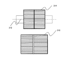
本発明の粉砕機の特徴は、図2に示す通り、該回転子314表面の凹凸部が、該中心回転軸312に対して平行に設けられていることにある。
The pulverizer according to the present invention is characterized in that the concavo-convex portion on the surface of the
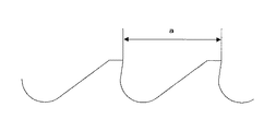
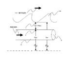
更に、本発明の粉砕機の特徴は、図3に示す、該回転子314及び固定子310表面の凸部と凸部との繰り返し距離aを、該回転子314表面の凸部と凸部との繰り返し距離をRa、該固定子310表面の凸部と凸部との繰り返し距離をLaとしたとき、該粉砕ゾーンにおいて、該RaとLaとが異なる範囲が存在するよう回転子314及び固定子310表面の凸部と凸部との繰り返し距離を設定することにある。
Further, the pulverizer of the present invention is characterized by the repetition distance a between the convex portions and the convex portions on the surfaces of the
更に、本発明の粉砕機の特徴は、図4から図6に示す通り、該回転子314において、該Raが異なる範囲が存在するよう、該回転子314表面の凸部と凸部との繰り返し距離を設定することにある。
Furthermore, as shown in FIGS. 4 to 6, the pulverizer of the present invention is characterized in that the surface of the
前述した通り、本発明者は、図1に示す粉砕機で、重量平均粒径6μm以下のトナー粒子を、単位時間当りの処理量がより高い状態で得るべく鋭意検討した結果、該回転子314表面の凸部と凸部との繰り返し距離と、該固定子310表面の凸部と凸部との繰り返し距離に着目した。
As described above, as a result of intensive investigations by the inventor to obtain toner particles having a weight average particle diameter of 6 μm or less with a higher processing amount per unit time using the pulverizer shown in FIG. Attention was paid to the repeated distance between the convex portions on the surface and the repeated distance between the convex portions on the surface of the
本発明者等が検討した結果、該回転子314及び固定子310表面における凸部と凸部との繰り返し距離を狭くすることで、重量平均粒径6μm以下のトナー粒子が得られることが分かった。
As a result of studies by the present inventors, it has been found that toner particles having a weight average particle diameter of 6 μm or less can be obtained by narrowing the repetition distance between the convex portions on the surfaces of the
上記の理由は定かではないが、該回転子314及び固定子310表面における凸部と凸部との繰り返し距離を狭くすることで、該回転子314及び固定子310表面の凹凸部数を増加する。凹凸部数が増加することにより、トナー粒子に対する衝撃力の数を多くすることができ、更に、該回転子314と該固定子310との間に発生する超高速の渦流の数を多くすることができるためと考えている。
Although the reason for this is not clear, the number of concavo-convex portions on the surfaces of the
しかしながら、更に検討した結果、ただ単に、該回転子314及び固定子310表面の凸部と凸部との繰り返し距離を狭くし、該回転子314及び固定子310表面の凹凸部数を増加させるだけでは、重量平均粒径6μm以下のトナー粒子を、単位時間当りの処理量をより高い状態で得ることは困難であることが分かった。
However, as a result of further examination, simply reducing the repetition distance between the convex portions on the surfaces of the
本発明者等は、更に検討した結果、
該回転子314表面の凸部と凸部との繰り返し距離をRa、
該固定子310表面の凸部と凸部との繰り返し距離をLaとしたとき、
該粉砕ゾーンにおいて、該Raと該Laが互いに異なる範囲が存在するよう、該回転子314及び固定子310表面の該凸部と該凸部との繰り返し距離を設定し、
該回転子314において、該Raが異なる範囲が存在するよう、該回転子314表面の該凸部と該凸部との繰り返し距離を設定することにより、
図1に示す粉砕機おいて、重量平均粒径6μm以下のトナー粒子を、単位時間当りの処理量をより高い状態で得られることが分かった。
As a result of further study, the present inventors
The repetition distance between the convex portions on the surface of the
When the repetition distance between the convex portions on the surface of the
In the grinding zone, the repetition distance between the convex portions and the convex portions on the surfaces of the
In the
In the pulverizer shown in FIG. 1, it has been found that toner particles having a weight average particle diameter of 6 μm or less can be obtained with a higher throughput per unit time.
更に本発明者等が検討した結果、
該Laが3.5mm未満の範囲をSLaとしたとき、
該固定子310表面の該凸部と該凸部との繰り返し距離を、全てSLaとし、且つ、
該回転子314表面の該Raが3.5mm以上の範囲をLRaとし、
該回転子314表面の該Raが3.5mm未満の範囲をSRaとしたとき、
LRa/SRaを0.1以上7.0以下とすることにより、
図1に示す粉砕機おいて、重量平均粒径6μm以下のトナー粒子を、単位時間当りの処理量をより高い状態で得られることが分かった。
Furthermore, as a result of examination by the inventors,
When the range where La is less than 3.5 mm is SLa,
The repetition distance between the convex portion and the convex portion on the surface of the
The range where the Ra on the surface of the
When the Ra of the surface of the
By setting LRa / SRa to 0.1 or more and 7.0 or less,
In the pulverizer shown in FIG. 1, it has been found that toner particles having a weight average particle diameter of 6 μm or less can be obtained with a higher throughput per unit time.
上記の理由は定かではないが、該LaをSLaとし、LRa/SRaを0.1以上7.0以下とすることにより、該粉砕ゾーンにおける回転子314と固定子310で、該凸部と該凸部との繰り返し距離が同じであるSRaとSLaが構成される。 Although the reason for this is not clear, by setting the La to SLa and the LRa / SRa to 0.1 to 7.0, the ridges and the SRa and SLa having the same repetition distance to the convex portion are configured.
更に、上述の構成と同時に、該凸部と該凸部との繰り返し距離が異なる該LRaとSLaが構成される。更に、該回転子314において、該凸部と該凸部との繰り返し距離が異なる該LRaとSRaが構成される。
Furthermore, simultaneously with the above-described configuration, the LRa and SLa having different repetition distances between the convex portion and the convex portion are configured. Further, in the
上述した該LRaとSLa、該LRaとSRaという、2つの異なる該凸部と該凸部との繰り返し距離により、重量平均粒径6μm以下のトナー粒子を、単位時間当りの処理量をより高い状態で得ることができると本発明者等は考えている。 The toner particles having a weight average particle diameter of 6 μm or less can be processed at a higher processing amount per unit time due to the repetition distance between the two different convex portions of the above-mentioned LRa and SLa and LRa and SRa. The present inventors believe that the above can be obtained.
つまり、該LRaとSLaにより、粉砕粒径の細分化と処理量の向上が図られ、該LRaとSRaにより、トナー粒子の段階的粉砕が図られるため、重量平均粒径6μm以下のトナー粒子を、単位時間当りの処理量をより高い状態で得ることができると本発明者等は考えている。 In other words, the LRa and SLa improve the pulverized particle size and improve the processing amount, and the LRa and SRa pulverize the toner particles step by step. Therefore, toner particles having a weight average particle size of 6 μm or less can be obtained. The present inventors consider that the processing amount per unit time can be obtained in a higher state.
また、本発明者が検討した結果、該回転子のLRa/SRaが0.1未満及び7.0を超える場合、重量平均粒径6μm以下のトナー粒子を得るためには、単位時間当りの処理量を低く設定しなければならずトナー生産性という点から十分満足できるものではない。 In addition, as a result of investigation by the present inventor, when LRa / SRa of the rotor is less than 0.1 and exceeds 7.0, in order to obtain toner particles having a weight average particle diameter of 6 μm or less, processing per unit time The amount must be set low, which is not satisfactory from the viewpoint of toner productivity.
また、本発明者が検討した結果、材料組成の違いにより、便宜該回転子314及び固定子310、及び回転子314表面の凸部と凸部の繰り返し距離を変更することにより、材料構成の変更による材料組成の変化に対応できる。
In addition, as a result of the study by the present inventors, due to the difference in the material composition, for convenience, the
つまり、材料組成の違いにより、便宜該回転子314のRaと、該固定子310のLaを異なる範囲が存在するよう該回転子314及び固定子310表面の凸部と凸部の繰り返し距離を設定し、且つ、該回転子314のLRa/SRaを変化させるよう該回転子314表面の凸部と凸部の繰り返し距離を設定することにより、材料構成の変更による材料組成の変化に対応できる。
That is, for the sake of convenience, the repetition distance between the convex portions and the convex portions on the surface of the
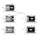
例えば、図4(a)においては、該固定子310におけるLaをSLaとし、且つ該回転子314を原料供給側と微粉砕物排出側とに2分割し、原料供給側における回転子314のLaをLRaとし、微粉砕物排出側における回転子314のLaをSRaとしている(従って、LRa/SRa=1.0)。
For example, in FIG. 4A, La in the
また、図4(b)においては、該固定子310におけるLaをSLaとし、且つ該回転子314を4分割し、原料供給側から微粉砕物排出側にかけて、夫々回転子314の番号をR1/R2/R3/R4とした場合、R1〜R3までをLRa、R4をSRaとしている(従って、LRa/SRa=3.0)。
Further, in FIG. 4B, La in the
また、図4(c)においては、該固定子310におけるLaをSLaとし、且つ該回転子314を4分割し、原料供給側から微粉砕物排出側にかけて、夫々回転子314の番号をR1/R2/R3/R4とした場合、R1をLRa、R2〜R4をSRaとしている(従って、LRa/SRa=0.3)。
In FIG. 4C, La in the
また、図4(d)においては、該該固定子310におけるLaをSLaとし、且つ該回転子314を8分割し、原料供給側から微粉砕物排出側にかけて、夫々回転子314の番号をR1/R2/R3/R4/R5/R6/R7/R8とした場合、R1〜R7をLRa、R8をSRaとしている(従って、LRa/SRa=7.0)。
Further, in FIG. 4D, La in the
また、図4(e)においては、該固定子310におけるLaをSLaとし、且つ該回転子314を8分割し、原料供給側から微粉砕物排出側にかけて、夫々回転子314の番号をR1/R2/R3/R4/R5/R6/R7/R8とした場合、R1をLRa、R2〜R8をSRaとしている(従って、LRa/SRa=0.14)。
Further, in FIG. 4E, La in the
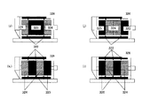
また、図5(a)においては、該固定子310におけるLaをSLaとし、且つ該回転子314を原料供給側と微粉砕物排出側とに2分割し、原料供給側における回転子314のLaをSRaとし、微粉砕物排出側における回転子314のLRaとしている(従って、LRa/SRa=1.0)。
Further, in FIG. 5A, La in the
また、図5(b)においては、該固定子310におけるLaをSLaとし、且つ該回転子314を4分割し、原料供給側から微粉砕物排出側にかけて、夫々回転子314の番号をR1/R2/R3/R4とした場合、R1〜R3をSRa、R4をLRaとしている(従って、LRa/SRa=0.3)。
Further, in FIG. 5B, La in the
また、図5(c)においては、該固定子310におけるLaをSLaとし、且つ該回転子314を4分割し、原料供給側から微粉砕物排出側にかけて、夫々回転子314の番号をR1/R2/R3/R4とした場合、R1をSRa、R2〜R4をLRaとしている(従って、LRa/SRa=3.0)。
Further, in FIG. 5C, La in the
また、図5(d)においては、該固定子310におけるLaをSLaとし、且つ該回転子314を8分割し、原料供給側から微粉砕物排出側にかけて、夫々回転子314の番号をR1/R2/R3/R4/R5/R6/R7/R8とした場合、R1〜R7をSRa、R8をLRaとしている(従って、LRa/SRa=0.14)。
Further, in FIG. 5D, La in the
また、図5(e)においては、該固定子310におけるLaをSLaとし、且つ該回転子314を8分割し、原料供給側から微粉砕物排出側にかけて、夫々回転子314の番号をR1/R2/R3/R4/R5/R6/R7/R8とした場合、R1をSRa、R2〜R8をLRaとしている(従って、LRa/SRa=7.0)。
Further, in FIG. 5E, La in the
また、図6(a)においては、該固定子310におけるLaをSLaとし、且つ該回転子314のR1/R4をLRa、該回転子314のR2/R3をSRaとしている(従って、LRa/SRa=1.0)。
In FIG. 6A, La in the
また、図6(b)においては、該固定子310におけるLaをSLaとし、且つ該回転子314のR1/R4をSRa、該回転子314のR2/R3をLRaとしている(従って、LRa/SRa=1.0)。
In FIG. 6B, La in the
また、図6(c)においては、該固定子310におけるLaをSLaとし、且つ該回転子314のR1/R3をLRa、該回転子314のR2/R4をSRaとしている(従って、LRa/SRa=1.0)。
In FIG. 6C, La in the
また、図6(d)においては、該固定子310におけるLaをSLaとし、且つ該回転子314のR1/R3をSRa、該回転子314のR2/R4をLRaとしている(従って、LRa/SRa=1.0)。
In FIG. 6D, La in the
更に、本発明の効果をより発揮する構成としては、回転子は内部に冷却用の冷媒流路を具備することが好ましい。 Furthermore, as a configuration that further exhibits the effects of the present invention, it is preferable that the rotor has a coolant flow path for cooling inside.
この理由としては、本発明の固定子及び回転子の構成を取る事で、粉砕性は飛躍的に改良され、この結果、単位時間あたりの処理量を増加させる事が可能となった。その反面、被粉砕物の粉砕機内における充満率は上昇し、装置内の昇温は厳しい方向となる。この対応として、装置内へ導入する冷風の温度を低下させる事も可能であるが、生産時エネルギーの増加と言った問題が生じる。そこで、回転子自体を直接内部から冷却する構成とする事で、生産性向上を低エネルギーで達成する事が可能となる。 The reason for this is that the grindability is drastically improved by adopting the configuration of the stator and the rotor of the present invention, and as a result, the processing amount per unit time can be increased. On the other hand, the filling rate of the object to be crushed in the pulverizer increases, and the temperature rise in the apparatus becomes severe. As a countermeasure for this, it is possible to reduce the temperature of the cold air introduced into the apparatus, but there arises a problem that the energy during production increases. Therefore, by adopting a configuration in which the rotor itself is directly cooled from the inside, it is possible to achieve improvement in productivity with low energy.
更に、本発明の粉砕機に用いる回転子314は、図9に示す通り、独立した複数個のディスク322を繋ぎ合せた回転子から構成され、該回転子は内部に冷却用の冷媒流路を具備することが好ましい。
Further, as shown in FIG. 9, the
この理由としては、本発明の回転子は表面の凸部と凸部との繰り返し距離が異なる範囲を有する為、通常の冷却水の入れ方ではバランス取りが難しく、特に高速回転領域での安定性に問題が生じる場合がある。 The reason for this is that the rotor of the present invention has a range in which the repetitive distance between the convex portion and convex portion on the surface is different, so that it is difficult to balance with ordinary cooling water, especially in the high-speed rotation region. May cause problems.
更に、本発明の回転子314内部における該冷媒流路は、図9に示す通り、
粉体投入口311側或いは、粉体排出口302側の一方向から、中心回転軸312を介して、冷媒を導入するための冷媒流路L、
該回転子314において外層部へ冷媒を搬送するための冷媒流路M、
該回転子314外層部を中心回転軸312と並行に冷媒を搬送するための冷媒流路N、
該回転子314外層部から中心回転軸312に向けて冷媒を搬送するための冷媒流路P、
冷媒導入方向に対して同方向域または逆方向への冷媒を排出するための冷媒流路Q、
の構成であることが好ましい。
Furthermore, the refrigerant flow path inside the
A refrigerant flow path L for introducing a refrigerant from one direction on the
A refrigerant flow path M for conveying the refrigerant to the outer layer portion in the
A refrigerant flow path N for conveying the refrigerant in parallel with the
A refrigerant flow path P for conveying the refrigerant from the outer layer portion of the
Refrigerant flow path Q for discharging refrigerant in the same direction region or in the opposite direction with respect to the refrigerant introduction direction,
It is preferable that it is the structure of these.
つまり、本発明の回転子314は、該各ディスク322内において外層部へ冷媒を搬送するための冷媒流路Mを、該ディスク322の枚数に合せて独立して設け、該ディスク322の枚数に合せて独立して設けた該冷媒流路Mに、該冷媒流路Lから冷媒を別々に導入することが可能な構成となっている。
That is, the
更に、本発明の回転子314は、該各ディスク322外層部から中心回転軸312に向けて冷媒を搬送するための冷媒流路Pを、該ディスク322の枚数に合せて独立して設け、該ディスクの枚数に合せて独立して設けた該冷媒流路Pから、冷媒流路Qに冷媒を別々に戻すことが可能な構成となっている。
Further, the
本発明者等が検討した結果、該回転子314を上述した構成とすることにより、該回転子314の高速回転に伴う、粉砕室内温度の昇温や本体振動値の増大、及び冷却効率の低下を低減でき、粉砕室内温度上昇による品質弊害や機内融着を防止することができる。
As a result of studies by the present inventors, the
更に、本発明者等が検討した結果、該回転子314を上述した冷媒流路を具備する回転子とし、合せて、該回転子314のRaと、該固定子310Laが、互いに異なる範囲が存在するよう、該回転子314及び固定子310表面の凸部と凸部の繰り返し距離を設定し、更に、該回転子314において、該Raが異なる範囲が存在するよう、該回転子314表面の凸部と凸部の繰り返し距離を設定することが好ましい。
Further, as a result of investigations by the present inventors, the
該回転子314を上述した構成とすることにより、単位時間当りの処理量をより向上させることができ、重量平均粒径6μm以下で、且つ、シャープな粒度分布を有するトナー粒子を、効率良く、安定的に、トナー生産性上良好に得ることができる。
By configuring the
該回転子314は内部に冷却用の冷媒流路を具備する構成とすることにより、単位時間当りの処理量を向上させることができる理由は定かではないが、トナー粒子粉砕時における発熱を、該冷媒流路に冷媒を通水することより、ある程度除熱できるためと考えている。
Although it is not clear why the
尚、本発明の回転子314は、該各ディスク322内において外層部へ冷媒を搬送するための冷媒流路M及び/または、該各ディスク322外層部から中心回転軸312に向けて冷媒を搬送するための冷媒流路Pは、独立した複数個のディスク322毎に、複数本から構成されることが好ましい。
Note that the
更に、本発明の回転子314は、該各ディスク322内において外層部へ冷媒を搬送するための冷媒流路Mにおける流路の数と、各ディスク322外層部から中心回転軸312に向けて冷媒を搬送するための冷媒流路Pにおける流路の数が、同数であることが好ましい。
Further, the
更に、上記流路M、及び上記流路Pのサイズは、各々の径と長さを等しくする事で遠心力による抵抗を相殺し、回転子314の回転数に影響されることなく安定した冷媒流量を得ることができる。
Further, the sizes of the flow path M and the flow path P are equal to each other in diameter and length, thereby canceling out the resistance caused by the centrifugal force and stable refrigerant without being affected by the rotational speed of the
更に本発明の粉砕機は、図8に示す通り、
該回転子314は、外周面に複数の凹部を有し、
該回転子314は内部に冷却用の冷媒流路を具備し、
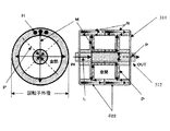
該回転子314の中心点pから該回転子の凹部底面rまでを直線で結んだ長さをDprとし、
該回転子314の中心点pから該冷媒流路の最外殻qまでを直線で結んだ長さをDpqとした場合、
以下の式(1)となるように、冷却用の冷媒流路を設けることが好ましい。
式(1) 1.0mm≦Dpr−Dpq≦25.0mm
Furthermore, as shown in FIG.
The
The
A length obtained by connecting a straight line from the center point p of the
When the length connecting the straight line from the center point p of the
It is preferable to provide a cooling coolant flow path so as to satisfy the following formula (1).
Formula (1) 1.0 mm <= Dpr-Dpq <= 25.0mm
更に本発明の粉砕機における該冷媒流路は、図8に示す通り、該中心回転軸312に対して並行に設けられた冷却孔Nであり、該冷却孔Nは、該中心回転軸方向と垂直な断面において、該回転子円周方向に、一定間隔に配置されていることが好ましい。
Further, as shown in FIG. 8, the refrigerant flow path in the pulverizer of the present invention is a cooling hole N provided in parallel to the
更に本発明の粉砕機における該冷却孔Nは、図8に示す、該中心回転軸方向と垂直な断面における断面積Dが、18mm2以上2000mm2以下の範囲であることが好ましい。 Further, the cooling hole N in the pulverizer of the present invention preferably has a cross-sectional area D in a cross section perpendicular to the central rotational axis direction shown in FIG. 8 in the range of 18 mm 2 or more and 2000 mm 2 or less.
更に、本発明者等が検討した結果、図8に示す、回転子314の中心点pから回転子314の凹部底面rまでを直線で結んだ長さをDpr、回転子314の中心点pから該冷媒流路の最外殻qまでを直線で結んだ長さをDpqとした場合、以下の式(1)となるように、冷却用の冷媒流路を設けることにより、該回転子314の高速回転においても、振動値を低減でき、高い冷却効率を得ることができることが分かった。
式(1) 1.0mm≦Dpr−Dpq≦25.0mm
Further, as a result of the study by the present inventors, the length obtained by connecting a straight line from the center point p of the
Formula (1) 1.0 mm <= Dpr-Dpq <= 25.0mm
本発明者等が検討した結果、式(1)において、Dpr−Dpqが1.0mm未満の場合、該回転子314の高速回転に伴う振動値が高くなり、該回転子314の高速回転時の安定運転という点から十分満足できるものではない。
As a result of studies by the present inventors, in the formula (1), when Dpr-Dpq is less than 1.0 mm, the vibration value associated with the high-speed rotation of the
更に、本発明者等が検討した結果、Dpr−Dpqが25.0mmを超える場合、今度は充分な冷却効果が得られないことから、単位時間当りの処理量を向上させることができず、トナー生産性という点から十分満足できるものではない。 Further, as a result of investigations by the present inventors, when Dpr-Dpq exceeds 25.0 mm, a sufficient cooling effect cannot be obtained this time, so the throughput per unit time cannot be improved, and the toner It is not satisfactory from the point of productivity.
更に、本発明者等が検討した結果、図8に示す通り、回転子314内部に具備する冷却用の冷媒流路を、冷却孔Hとし、更に該冷却孔Hを一定間隔に配置することにより、該回転子314の高速回転に伴う、振動値を低減でき、高い冷却効率を得ることができることが分かった。
Further, as a result of the study by the present inventors, as shown in FIG. 8, the cooling coolant flow path provided in the
本発明者等が検討した結果、冷媒流路を冷却孔Hとすることで、機械的強度を確保した上で冷却孔Hを回転子314表層近傍に近付けることができる。更に、冷却孔Hとすることで、必要最小限の冷媒でムラの少ない効率的な冷却を得ることができる。
As a result of investigations by the present inventors, by setting the coolant flow path as the cooling hole H, the cooling hole H can be brought close to the surface layer of the
更に、冷却孔Hの配置は、中心回転軸312と並行する複数の冷却孔を一定間隔に配置することで、極めて大きな冷却面積を得ることができる。
Furthermore, the cooling holes H can be arranged by arranging a plurality of cooling holes parallel to the central
また、冷却孔Hの形状は、加工性や容積精度の面から円筒状のドリルホールが好ましいが、放電加工法やレーザー加工法等により三角形四角形或いは星形の様な多角形でも同様の効果が得られる。また、それらの組合せでも良い。 The shape of the cooling hole H is preferably a cylindrical drill hole from the viewpoint of workability and volumetric accuracy, but the same effect can be obtained by a polygon such as a triangular quadrangle or a star by electric discharge machining or laser machining. can get. Also, a combination thereof may be used.
更に、冷却孔Hの配置は、二列三列と複数の列を成すことで、更に冷却効率を向上することができる。更に、冷却孔Nを中心回転軸312と並行に配置することで冷媒の揺動を抑え、回転子314を安定して高速回転させることができる。
Further, the cooling holes H can be arranged in two rows and three rows and a plurality of rows to further improve the cooling efficiency. Furthermore, by disposing the cooling hole N in parallel with the
また、複数個の冷却孔Hは各々の容積を統一し等間隔に配置することで、冷媒の有無によるアンバランスを解消し冷媒の有無に影響されることなく、回転子314を安定して高速回転させることができる。
In addition, the plurality of cooling holes H have the same volume and are arranged at equal intervals to eliminate imbalance due to the presence or absence of the refrigerant, and to stably and rapidly rotate the
尚、冷却孔Hの両端面は、複数個の冷却孔Hを連結する空間を設けた上で、胴淵を溶接、またはプレートをOリング等のシール材によって密閉する。 In addition, the both end surfaces of the cooling hole H are provided with spaces for connecting the plurality of cooling holes H, and the cylinder is welded or the plate is sealed with a sealing material such as an O-ring.
更に、本発明者等が検討した結果、図8に示す、該冷却孔Hの該中心回転軸方向と垂直な断面における断面積Dが、18mm2以上2000mm2以下の範囲とすることにより、該回転子314の高速回転においても、振動値を低減でき、高い冷却効率を得ることができることが分かった。
Furthermore, as a result of the study by the present inventors, the cross-sectional area D in the cross section perpendicular to the central rotation axis direction of the cooling hole H shown in FIG. 8 is in the range of 18 mm 2 or more and 2000 mm 2 or less. It was found that even at high speed rotation of the
本発明者等が検討した結果、該冷却孔Hの該中心回転軸方向と垂直な断面における断面積Dが、18mm2未満の場合、該冷却孔Hを製作するための加工工数が増加し、イニシャルコストの面から十分満足できるものではない。 As a result of studies by the present inventors, when the cross-sectional area D in the cross section perpendicular to the central rotational axis direction of the cooling hole H is less than 18 mm 2 , the number of processing steps for manufacturing the cooling hole H increases. The initial cost is not fully satisfactory.
更に、本発明者等が検討した結果、該冷却孔Hの該中心回転軸方向と垂直な断面における断面積Dが、2000mm2を超える場合、充分な冷却効果が得られず、また該回転子314の重量増加が伴うため、該回転子314の高速回転時の安定運転という点から十分満足できるものではない。
Further, as a result of the study by the present inventors, when the cross-sectional area D in the cross section perpendicular to the central rotation axis direction of the cooling hole H exceeds 2000 mm 2 , a sufficient cooling effect cannot be obtained, and the rotor Since the increase in the weight of 314 is accompanied, the
更に本発明は、結着樹脂及び着色剤を少なくとも含有する重量平均粒子径が4μm乃至12μmのトナー製造方法に用いられるトナー製造装置において、
該トナー粒子は、少なくとも、溶融混練工程及び粗粉砕工程、微粉砕工程、分級工程を経て生成されたものであって、
該微粉砕工程に用いられる装置は、被粉砕物を粉砕手段内に投入するための粉体投入口311と、固定子310と、少なくとも中心回転軸312に取り付けられた回転子314と、粉砕された粉体を粉砕手段から排出するための粉体排出口302とを少なくとも有し、
該固定子310は該回転子314を内包しており、
該固定子310表面と該回転子314表面とは、所定の間隙を有するように該回転子314は配置されて粉砕ゾーンを形成しており、
該粉砕ゾーンにおいて、該回転子314の回転に伴って被粉砕物が粉砕され、
該固定子310表面及び回転子314表面は、いずれも複数の凸部と凹部とを有する粉砕機であり、
該凹凸部が、該中心回転軸312に沿うよう設けられており、
該回転子314は内部に冷却用の冷媒流路を具備し、
該回転子314表面の凸部と凸部との繰り返し距離をRa、
該固定子314表面の凸部と凸部との繰り返し距離をLaとしたとき、
該粉砕ゾーンにおいて、該Raと該Laが互いに異なる範囲が存在するよう、該回転子314及び固定子310表面の凸部と凸部との繰り返し距離を設定し、
該回転子314において、該Raが異なる範囲が存在するよう、該回転子314表面の凸部と凸部との繰り返し距離を設定することを特徴とする。
Furthermore, the present invention relates to a toner production apparatus used in a toner production method having a weight average particle size of 4 μm to 12 μm, which contains at least a binder resin and a colorant.
The toner particles are produced through at least a melt-kneading step, a coarse pulverization step, a fine pulverization step, and a classification step,
The apparatus used in the fine pulverization step is pulverized with a
The
The
In the pulverization zone, the object to be crushed is pulverized as the
The
The uneven portion is provided along the
The
The repetition distance between the convex portions on the surface of the
When the repetition distance between the convex portion and convex portion on the surface of the
In the pulverization zone, the repetition distance between the convex portions and the convex portions on the surface of the
In the
該粉砕機を上述した構成とすることにより、単位時間当りの処理量をより向上させることができ、重量平均粒径6μm以下で、且つ、シャープな粒度分布を有するトナー粒子を、効率良く、安定的に、トナー生産性上良好に得ることができる。 By configuring the pulverizer as described above, the throughput per unit time can be further improved, and toner particles having a weight average particle size of 6 μm or less and a sharp particle size distribution can be efficiently and stably obtained. In particular, it can be obtained with good toner productivity.
また、本発明のトナー製造装置においては、該粉砕機内の回転子314表面と固定子310表面との間の最小間隔は0.5乃至5.0mmであることが好ましく、0.5乃至2.0mmとすることが更に好ましい。
In the toner production apparatus of the present invention, the minimum distance between the surface of the
該粉砕機内の回転子314と固定子310との間の最小間隔が0.5mm未満の場合、装置自体の負荷が大きくなるのと同時に、粉砕時に過粉砕され、トナーの熱変質や機内融着を起こしやすいのでこちらもトナー生産性という点から十分満足できるものではない。
When the minimum distance between the
また、該粉砕機内の回転子314と固定子310との間の最小間隔が5.0mmを超える場合、粉砕されずにショートパスを起こしてしまいトナー生産性という点から十分満足できるものではない。
In addition, when the minimum distance between the
更に、本発明のトナー製造装置においては、該回転子314の回転周速は30m/sec乃至180m/secとすることが好ましく、更には、40m/sec乃至170m/secとすることが好ましい。
Further, in the toner manufacturing apparatus of the present invention, the rotational peripheral speed of the
本発明者が検討した結果、該回転子314の回転周速を30m/sec未満とすると、小粒径のトナーを得るためには単位時間当りの処理量を落とさなければならず、トナー生産性上十分満足できるものではない。
As a result of studies by the present inventors, if the rotational peripheral speed of the
また、該回転子314の回転周速を180m/secを超えるものとすると、装置自体の負荷が大きくなるのと同時に、粉砕時に被粉砕物が過粉砕されると同時に、熱による表面変質や機内融着を起こしやすいので、こちらもトナー生産性という点から十分満足できるものではない。
Also, if the rotational peripheral speed of the
次に、本発明のトナー製造装置を用いて、トナーを製造する手順について説明する。 Next, a procedure for producing toner using the toner production apparatus of the present invention will be described.
まず、原料混合工程では、トナー内添剤として、少なくとも樹脂、着色剤を所定量秤量して配合し、混合する。混合装置の一例としては、ヘンシェルミキサー(三井鉱山社製);スーパーミキサー(カワタ社製);リボコーン(大川原製作所社製);ナウターミキサー、タービュライザー、サイクロミックス(ホソカワミクロン社製);スパイラルピンミキサー(太平洋機工社製);レーディゲミキサー(マツボー社製)等がある。 First, in the raw material mixing step, as a toner internal additive, at least a resin and a colorant are weighed and mixed in a predetermined amount and mixed. As an example of a mixing device, Henschel mixer (Mitsui Mining Co., Ltd.); Super mixer (Kawata Co., Ltd.); Ribocorn (Okawara Seisakusho Co., Ltd.); There are mixers (manufactured by Taiheiyo Kiko Co., Ltd.);
更に、上記で配合し、混合したトナー原料を溶融混練工程にて、溶融混練して、樹脂類を溶融し、その中の着色剤等を分散させる。混練装置の一例としては、TEM型押し出し機(東芝機械社製);TEX二軸混練機(日本製鋼所社製);PCM混練機(池貝鉄工所社製);ニーデックス(三井鉱山社製)等が挙げられるが、連続生産できる等の優位性から、バッチ式練り機よりも、1軸または2軸押出機といった連続式の練り機が好ましい。 Further, the toner raw materials blended and mixed as described above are melt-kneaded in a melt-kneading step to melt the resins and disperse the colorant and the like therein. As an example of a kneading apparatus, a TEM type extruder (manufactured by Toshiba Machine Co., Ltd.); a TEX twin-screw kneader (manufactured by Nippon Steel Works); a PCM kneader (manufactured by Ikekai Iron Works Co., Ltd.); However, a continuous kneader such as a single-screw or twin-screw extruder is preferable to a batch kneader because of the advantage of being capable of continuous production.
更に、トナー原料を溶融混練することによって得られる着色樹脂組成物は、溶融混練後、2本ロール等で圧延され、水冷等で冷却する冷却工程を経て冷却される。 Furthermore, the colored resin composition obtained by melt-kneading the toner raw material is rolled by a two-roll roll after melt-kneading, and then cooled through a cooling step of cooling by water cooling or the like.
上記で得られた着色樹脂組成物の冷却物は、次いで、粉砕工程で所望の粒径にまで粉砕される。粉砕工程では、まず、クラッシャー、ハンマーミル、フェザーミル等で粗粉砕され、更に、上述した本発明の粉砕機で微粉砕される。 The cooled product of the colored resin composition obtained above is then pulverized to a desired particle size in a pulverization step. In the pulverization step, first, coarse pulverization is performed by a crusher, a hammer mill, a feather mill or the like, and further, fine pulverization is performed by the above-described pulverizer of the present invention.
粉砕工程で得られた微粉砕物を、分級工程にて、所望の粒径を有するトナー粒子に分級される。分級機としては、ターボプレックス、TSPセパレータ、TTSPセパレータ(ホソカワミクロン社製);エルボージェット(日鉄鉱業社製)等がある。 The finely pulverized product obtained in the pulverization step is classified into toner particles having a desired particle size in the classification step. Examples of the classifier include a turboplex, a TSP separator, a TTSP separator (manufactured by Hosokawa Micron), and an elbow jet (manufactured by Nippon Steel Mining).
更に必要に応じて、表面改質工程で表面改質=球形化処理を行ない、表面改質粒子とすることもできる。表面改質機の一例としては、ハイブリタイゼーションシステム(奈良機械製作所製);ノビルタ(ホソカワミクロン社製)等がある。 Further, if necessary, surface modification = spheronization treatment may be performed in the surface modification step to form surface modified particles. Examples of the surface reformer include a hybridization system (manufactured by Nara Machinery Co., Ltd.); Nobilta (manufactured by Hosokawa Micron Corporation) and the like.
表面改質後、必要に応じて、粗粒等を篩い分けるために、例えば、ウルトラソニック(晃栄産業社製);レゾナシーブ、ジャイロシフター(徳寿工作所社);ターボスクリーナー(ターボ工業社製);ハイボルター(東洋ハイテック社製)等の篩分機を用いても良い。 After surface modification, for example, Ultrasonic (manufactured by Sakae Sangyo Co., Ltd.); Resona sieve, gyro shifter (Tokuju Kogakusha Co., Ltd.); Turbo screener (manufactured by Turbo Kogyo Co., Ltd.) ); A sieving machine such as a high volter (manufactured by Toyo Hitec Co., Ltd.) may be used.
得られたトナー粒子に、必要に応じて無機微粒子等の外添剤を外添することでトナーを得る。トナー粒子に外添剤を外添処理する方法としては、トナー粒子と公知の各種外添剤を所定量配合し、ヘンシェルミキサー、メカノハイブリッド(三井鉱山社製);スーパーミキサー等の粉体にせん断力を与える高速撹拌機を外添機として用いて、撹拌・混合する。 A toner is obtained by externally adding external additives such as inorganic fine particles to the obtained toner particles as necessary. As a method of externally adding an external additive to toner particles, a predetermined amount of toner particles and various known external additives are blended, and sheared into a powder such as a Henschel mixer, Mechano Hybrid (Mitsui Mining Co., Ltd.); Stir and mix using a high-speed stirrer that gives force as an external additive.
尚、本発明者が検討した結果、前述した該粉砕工程の後工程、或いは該分級工程で得られたトナー粒子を表面改質処理することにより、良好な現像性、転写性並びにクリーニング性、及び安定した帯電性を有する、長寿命のトナーを得られること分かった。 In addition, as a result of examination by the present inventors, the toner particles obtained in the subsequent step of the pulverization step or the classification step are subjected to a surface modification treatment, so that good developability, transferability, cleaning property, and It has been found that a long-life toner having a stable charging property can be obtained.
本発明のトナーの製造方法に好適に用いられる回分式の表面改質装置について図10を用いて説明する。 A batch type surface modification apparatus suitably used in the toner production method of the present invention will be described with reference to FIG.
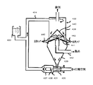
図10に示す回分式の表面改質装置は、円筒形状の本体ケーシング30、本体ケーシングの上部に開閉可能なよう設置された天板43;微粉排出ケーシングと微粉排出管とを有する微粉排出部44;冷却水或いは不凍液を通水できる冷却ジャケット31を有している。
The batch type surface modification apparatus shown in FIG. 10 includes a cylindrical
更に、図10に示す回分式の表面改質装置は、表面改質手段としての、本体ケーシング30内にあって中心回転軸に取り付けられた、上面に角型ディスクである分散ハンマー33を複数個有し、所定方向に高速に回転する円盤状の回転体である分散ローター32;分散ローター32の周囲に一定間隔を保持して固定配置された、分散ローター32に対向する表面に多数の溝が設けられているライナー34を有している。
Furthermore, the batch-type surface modification apparatus shown in FIG. 10 has a plurality of dispersion hammers 33, which are square disks, on the upper surface, which are attached to the central rotating shaft in the main body casing 30 as surface modification means. A distributed
更に、図10に示す回分式の表面改質装置は、粉体粒子中の所定粒径以下の微粉を連続的に除去するための分級ローター35;本体ケーシング30内に冷風を導入するための冷風導入口46;粉体粒子(原料)を導入するために本体ケーシング30の側面に形成された原料投入口37及び原料供給口39を有する投入管を有している。
Furthermore, the batch-type surface modification apparatus shown in FIG. 10 includes a classification rotor 35 for continuously removing fine powder having a predetermined particle diameter or less in the powder particles; cold air for introducing cold air into the
更に、図10に示す回分式の表面改質装置は、表面改質処理後のトナー粒子を本体ケーシング30外に排出するための製品排出口40及び製品抜取口42を有する製品排出管;表面改質時間を自在に調整できるように、原料投入口37と原料供給口39との間に設置された開閉可能な原料供給弁38;及び製品排出口40と製品抜取口42との間に設置された製品排出弁41を有している。
10 is a product discharge pipe having a
更に、図10に示す回分式の表面改質装置は、天板43に対して垂直な軸を有する円筒状の案内手段としてのガイドリング36を本体ケーシング30内に有している。このガイドリング36は、先述した通り、該ガイドリングの上端部分が天板内面と密着しており、分級ローター36がその円筒に覆われた状態で設置されている。
Further, the batch type surface modification apparatus shown in FIG. 10 has a guide ring 36 as a cylindrical guide means having an axis perpendicular to the
また、ガイドリング36の下端は分散ローター32の円盤部または角形ディスクである分散ハンマー33から所定距離離間して設けられる。このガイドリング36によって装置内において分級ローター35と分散ローター32−ライナー34との間の空間が、ガイドリング外側の第一の空間47と、ガイドリング内側の第二の空間48とに二分される。
The lower end of the guide ring 36 is provided at a predetermined distance from the disc portion of the dispersing
ここで、第一の空間47は粉体粒子を分級ローター35へ導入するための空間であり、第二の空間は粉体粒子を分散ローターに導入するための空間である。
Here, the
分散ローター32上に複数個設置された角型のディスクである分散ハンマー33と、ライナー34との間隙部分が表面改質ゾーン49であり、分級ローター35及び該ローター周辺部分が分級ゾーン50である。
A gap between the
以上のように構成してなる回分式の表面改質装置では、製品排出弁39を閉とした状態で、原料供給弁38を開とし、原料投入口37から被表面改質粒子を投入し、一定時間経過後原料供給弁38を閉とする。
In the batch-type surface reforming apparatus configured as described above, with the
原料供給口39より装置内に投入された粉体粒子は、まずブロワ364により吸引され、分級ローター35で分級される。その際、分級された所定粒径以下の微粉は、微粉排出ケーシング44、微粉排出口45を通り装置外へ連続的に排出除去される。
The powder particles introduced into the apparatus from the raw
所定粒径以上の粉体粒子は遠心力によりガイドリング36の内周(第二の空間48)に沿い、旋回しながら、分散ローター32により発生する循環流にのり表面改質ゾーン49へ導かれる。
Powder particles having a predetermined particle diameter or more are guided along the inner circumference (second space 48) of the guide ring 36 by centrifugal force, and are circulated along the circulating flow generated by the
表面改質ゾーン49に導かれた粉体粒子は、分散ローター32上に複数個設置された角型のディスクである分散ハンマー33と、ライナー34との間で機械式衝撃力を受け、表面改質される。
The powder particles guided to the
表面改質された粉体粒子は、機内を通過する冷風及びブロワ吸引流にのって、ガイドリング36の外周(第一の空間47)に沿い、旋回しながら分級ゾーン50に導かれ、分級ローター35により、再度微粉は微粉排出ケーシング44、微粉排出口45を通り機外へ排出され、粗粉体は、循環流にのり、再度表面改質ゾーン49に戻され、繰り返し表面改質作用を受ける。
The surface-modified powder particles are guided to the
一定時間経過後、製品排出弁41を開とし、製品抜取口42より表面改質粒子を回収する。
After a certain period of time, the
尚、該回分式の表面改質装置で発生した微粉体は、サイクロン、バグ等の捕集機器により回収し、トナー原料の配合工程に戻して再利用することがトナー生産性上好ましい。 It is preferable in terms of toner productivity that the fine powder generated by the batch-type surface reforming apparatus is collected by a collecting device such as a cyclone or a bag and returned to the toner raw material mixing step and reused.
以上説明したように、本発明の粉砕機でトナー粒子を微粉砕し、得られた微粉砕物を図10に示す回分式の表面改質機で表面改質処理することにより、良好な現像性、転写性並びにクリーニング性、及び安定した帯電性を有する、長寿命のトナーを得ることができる。 As described above, the toner particles are finely pulverized by the pulverizer of the present invention, and the resulting finely pulverized product is surface-modified by the batch type surface reformer shown in FIG. In addition, it is possible to obtain a long-life toner having transferability, cleaning property, and stable chargeability.
次に、本発明においてその目的を達成するに好ましいトナーの構成を以下に詳述する。 Next, a preferable toner configuration for achieving the object in the present invention will be described in detail below.
本発明に用いられる結着樹脂としては、ビニル系樹脂、ポリエステル系樹脂、エポキシ樹脂等が挙げられる。中でもビニル系樹脂とポリエステル系樹脂が帯電性や定着性でより好ましい。特にポリエステル系樹脂を用いた場合には本装置の導入による効果は大きい。 Examples of the binder resin used in the present invention include vinyl resins, polyester resins, and epoxy resins. Of these, vinyl resins and polyester resins are more preferable in terms of chargeability and fixability. In particular, when a polyester resin is used, the effect of introducing this apparatus is great.
本発明において、ビニル系モノマーの単重合体または共重合体、ポリエステル、ポリウレタン、エポキシ樹脂、ポリビニルブチラール、ロジン、変性ロジン、テルペン樹脂、フェノール樹脂、脂肪族または脂環族炭化水素樹脂、芳香族系石油樹脂等を、必要に応じて前述した結着樹脂に混合して用いることができる。 In the present invention, vinyl monomer monopolymer or copolymer, polyester, polyurethane, epoxy resin, polyvinyl butyral, rosin, modified rosin, terpene resin, phenol resin, aliphatic or alicyclic hydrocarbon resin, aromatic Petroleum resin or the like can be mixed with the above-described binder resin as necessary.
2種以上の樹脂を混合して、結着樹脂として用いる場合、より好ましい形態としては分子量の異なるものを適当な割合で混合するのが好ましい。 When two or more kinds of resins are mixed and used as a binder resin, it is preferable that those having different molecular weights are mixed in an appropriate ratio as a more preferable form.
結着樹脂のガラス転移温度は好ましくは45〜80℃、より好ましくは55〜70℃であり、数平均分子量(Mn)は2,500〜50,000、重量平均分子量(Mw)は10,000〜1,000,000であることが好ましい。 The glass transition temperature of the binder resin is preferably 45 to 80 ° C., more preferably 55 to 70 ° C., the number average molecular weight (Mn) is 2,500 to 50,000, and the weight average molecular weight (Mw) is 10,000. -1,000,000 are preferred.
結着樹脂としては以下に示すポリエステル樹脂も好ましい。ポリエステル樹脂は、全成分中45〜55mol%がアルコール成分であり、55〜45mol%が酸成分である。 As the binder resin, the following polyester resins are also preferable. In the polyester resin, 45 to 55 mol% of all components is an alcohol component, and 55 to 45 mol% is an acid component.
ポリエステル樹脂の酸価は好ましくは90mgKOH/g以下、より好ましくは50mgKOH/g以下であり、OH価は好ましくは50mgKOH/g以下、より好ましくは30mgKOH/g以下であることが良い。これは、分子鎖の末端基数が増えるとトナーの帯電特性において環境依存性が大きくなる為である。 The acid value of the polyester resin is preferably 90 mgKOH / g or less, more preferably 50 mgKOH / g or less, and the OH value is preferably 50 mgKOH / g or less, more preferably 30 mgKOH / g or less. This is because as the number of terminal groups of the molecular chain increases, the dependency of the toner on the environment increases in the environment.
ポリエステル樹脂のガラス転移温度は好ましくは50〜75℃、より好ましくは55〜65℃であることが良い。さらに数平均分子量(Mn)は好ましくは1,500〜50,000、より好ましくは2,000〜20,000であり、重量平均分子量(Mw)は好ましくは6,000〜100,000、より好ましくは10,000〜90,000であることが良い。 The glass transition temperature of the polyester resin is preferably 50 to 75 ° C, more preferably 55 to 65 ° C. Further, the number average molecular weight (Mn) is preferably 1,500 to 50,000, more preferably 2,000 to 20,000, and the weight average molecular weight (Mw) is preferably 6,000 to 100,000, more preferably. Is preferably 10,000 to 90,000.
本発明のトナーを磁性トナーとして用いる場合、磁性トナーに含まれる磁性材料としては、マグネタイト、マグヘマイト、フェライトの如き酸化鉄、及び他の金属酸化物を含む酸化鉄;Fe,Co,Niのような金属、あるいは、これらの金属とAl,Co,Cu,Pb,Mg,Ni,Sn,Zn,Sb,Be,Bi,Cd,Ca,Mn,Se,Ti,W,Vのような金属との合金、およびこれらの混合物等が挙げられる。 When the toner of the present invention is used as a magnetic toner, the magnetic material contained in the magnetic toner includes iron oxides such as magnetite, maghemite and ferrite, and iron oxides including other metal oxides; Fe, Co, Ni, etc. Metals or alloys of these metals with metals such as Al, Co, Cu, Pb, Mg, Ni, Sn, Zn, Sb, Be, Bi, Cd, Ca, Mn, Se, Ti, W, V , And mixtures thereof.
具体的には、磁性材料としては、四三酸化鉄(Fe3O4)、三二酸化鉄(γ−Fe2O3)、酸化鉄亜鉛(ZnFe2O4)、酸化鉄イットリウム(Y3Fe5O12)、酸化鉄カドミウム(CdFe2O4)、酸化鉄ガドリニウム(Gd3Fe5O12)、酸化鉄銅(CuFe2O4)、酸化鉄鉛(PbFe12O19)、酸化鉄ニッケル(NiFe2O4)、酸化鉄ネオジム(NdFe2O3)、酸化鉄バリウム(BaFe12O19)、酸化鉄マグネシウム(MgFe2O4)、酸化鉄マンガン(MnFe2O4)、酸化鉄ランタン(LaFeO3)、鉄粉(Fe)、コバルト粉(Co)、ニッケル粉(Ni)等が挙げられる。 Specifically, examples of magnetic materials include triiron tetroxide (Fe 3 O 4 ), iron sesquioxide (γ-Fe 2 O 3 ), iron oxide zinc (ZnFe 2 O 4 ), and iron yttrium oxide (Y 3 Fe). 5 O 12 ), iron cadmium oxide (CdFe 2 O 4 ), iron gadolinium oxide (Gd 3 Fe 5 O 12 ), iron oxide copper (CuFe 2 O 4 ), lead iron oxide (PbFe 12 O 19 ), nickel iron oxide (NiFe 2 O 4 ), iron neodymium (NdFe 2 O 3 ), iron barium oxide (BaFe 12 O 19 ), iron magnesium oxide (MgFe 2 O 4 ), iron manganese oxide (MnFe 2 O 4 ), iron lanthanum oxide (LaFeO 3 ), iron powder (Fe), cobalt powder (Co), nickel powder (Ni) and the like.
上述した磁性材料を単独で或いは2種以上の組合せて使用する。特に好適な磁性材料は、四三酸化鉄またはγ−三二酸化鉄の微粉末である。 The magnetic materials described above are used alone or in combination of two or more. A particularly suitable magnetic material is a fine powder of iron tetroxide or γ-iron sesquioxide.
これらは結着樹脂100質量部に対して、磁性体20〜150質量部、好ましくは50〜130質量部、更に好ましくは60〜120質量部使用するのが良い。 These may be used in an amount of 20 to 150 parts by mass, preferably 50 to 130 parts by mass, and more preferably 60 to 120 parts by mass with respect to 100 parts by mass of the binder resin.
本発明のトナーに使用できる非磁性の着色剤としては、任意の適当な顔料または染料が挙げられる。 Non-magnetic colorants that can be used in the toner of the present invention include any suitable pigment or dye.
例えば顔料として、カーボンブラック、アニリンブラック、アセチレンブラック、ナフトールイエロー、ハンザイエロー、ローダミンレーキ、アリザリンレーキ、ベンガラ、フタロシアニンブルー、インダンスレンブルー等がある。 Examples of the pigment include carbon black, aniline black, acetylene black, naphthol yellow, hansa yellow, rhodamine lake, alizarin lake, bengara, phthalocyanine blue, and indanthrene blue.
これらは結着樹脂100質量部に対し0.1〜20質量部、好ましくは1〜10質量部の添加量が良い。また、同様に染料が用いられ、例えば、アントラキノン系染料、キサンテン系染料、メチン系染料があり、結着樹脂100質量部に対し0.1〜20質量部、好ましくは0.3〜10質量部の添加量が良い。 These are added in an amount of 0.1 to 20 parts by weight, preferably 1 to 10 parts by weight, based on 100 parts by weight of the binder resin. Similarly, dyes are used, for example, anthraquinone dyes, xanthene dyes, methine dyes, and 0.1 to 20 parts by weight, preferably 0.3 to 10 parts by weight with respect to 100 parts by weight of the binder resin. The addition amount of is good.
本発明のトナーは、その帯電性をさらに安定化させる為に必要に応じて荷電制御剤を用いることができる。荷電制御剤は、結着樹脂100質量部当り0.5〜10質量部使用するのが好ましい。 In the toner of the present invention, a charge control agent can be used as necessary in order to further stabilize the chargeability. The charge control agent is preferably used in an amount of 0.5 to 10 parts by mass per 100 parts by mass of the binder resin.
0.5質量部未満となる場合には、十分な帯電特性が得られない場合があり好ましくなく、10質量部を超える場合には、他材料との相溶性が悪化したり、低湿下において帯電過剰になったりする場合があり好ましくない。 When the amount is less than 0.5 parts by mass, sufficient charging characteristics may not be obtained, which is not preferable. When the amount exceeds 10 parts by mass, compatibility with other materials is deteriorated or charging is performed under low humidity. It may be excessive, which is not preferable.
荷電制御剤としては、以下のものが挙げられる。 Examples of the charge control agent include the following.
トナーを負荷電性に制御する負荷電性制御剤として、例えば有機金属錯体またはキレート化合物が有効である。モノアゾ金属錯体、芳香族ヒドロキシカルボン酸の金属錯体、芳香族ジカルボン酸系の金属錯体が挙げられる。他には、芳香族ハイドロキシカルボン酸、芳香族モノ及びポリカルボン酸及びその金属塩、その無水物、またはそのエステル類、または、ビスフェノールのフェノール誘導体類が挙げられる。 As a negative charge control agent for controlling the toner to be negative charge, for example, an organometallic complex or a chelate compound is effective. Examples include monoazo metal complexes, aromatic hydroxycarboxylic acid metal complexes, and aromatic dicarboxylic acid metal complexes. Others include aromatic hydroxycarboxylic acids, aromatic mono and polycarboxylic acids and their metal salts, anhydrides or esters thereof, or phenol derivatives of bisphenol.
トナーを正荷電性に制御する正荷電性制御剤としては、ニグロシン及び脂肪酸金属塩等による変性物、トリブチルベンジルアンモニウム−1−ヒドロキシ−4−ナフトスルホン酸塩、テトラブチルアンモニウムテトラフルオロボレート等の4級アンモニウム塩、及びこれらの類似体であるホスホニウム塩等のオニウム塩及びこれらのキレート顔料として、トリフェニルメタン染料及びこれらのレーキ顔料(レーキ化剤としては、燐タングステン酸、燐モリブデン酸、燐タングステンモリブデン酸、タンニン酸、ラウリン酸、没食子酸、フェリシアン酸、フェロシアン化合物等)、高級脂肪酸の金属塩として、ジブチルスズオキサイド、ジオクチルスズオキサイド、ジシクロヘキシルスズオキシド等のジオルガノスズオキサイドやジブチルスズボレート、ジオクチルスズボレート、ジシクロヘキシルスズボレート等のジオルガノスズボレートが挙げられる。 Examples of positive charge control agents for controlling the toner to be positively charged include modified products such as nigrosine and fatty acid metal salts, tributylbenzylammonium-1-hydroxy-4-naphthosulfonate, tetrabutylammonium tetrafluoroborate and the like. As onium salts such as quaternary ammonium salts and their analogs such as phosphonium salts and their chelating pigments, triphenylmethane dyes and their lake pigments (as rake agents, phosphotungstic acid, phosphomolybdic acid, phosphotungsten) Molybdic acid, tannic acid, lauric acid, gallic acid, ferricyanic acid, ferrocyanic compounds, etc.), diorganotin oxides such as dibutyltin oxide, dioctyltin oxide, dicyclohexyltin oxide and dibutyltin as metal salts of higher fatty acids , Dioctyl tin borate include diorgano tin borate such as dicyclohexyl tin borate.
本発明において、必要に応じて一種または二種以上の離型剤を、トナー粒子中に含有させてもかまわない。離型剤としては次のものが挙げられる。 In the present invention, if necessary, one or more release agents may be contained in the toner particles. Examples of the release agent include the following.
即ち、低分子量ポリエチレン、低分子量ポリプロピレン、マイクロクリスタリンワックス、パラフィンワックスなどの脂肪族炭化水素系ワックス、また、酸化ポリエチレンワックスなどの脂肪族炭化水素系ワックスの酸化物、または、それらのブロック共重合物;
カルナバワックス、サゾールワックス、モンタン酸エステルワックスなどの脂肪酸エステルを主成分とするワックス類;及び脱酸カルナバワックスなどの脂肪酸エステル類を一部または全部を脱酸化したものなどが挙げられる。
That is, aliphatic hydrocarbon waxes such as low molecular weight polyethylene, low molecular weight polypropylene, microcrystalline wax, and paraffin wax, and oxides of aliphatic hydrocarbon waxes such as oxidized polyethylene wax, or block copolymers thereof. ;
And waxes mainly composed of fatty acid esters such as carnauba wax, sazol wax, and montanic acid ester wax; and those obtained by partially or fully deoxidizing fatty acid esters such as deoxidized carnauba wax.
更に、パルミチン酸、ステアリン酸、モンタン酸などの飽和直鎖脂肪酸類;ブラシジン酸、エレオステアリン酸、バリナリン酸などの不飽和脂肪酸類;
ステアリルアルコール、アラルキルアルコール、ベヘニルアルコール、カルナウビルアルコール、セリルアルコール、メリシルアルコールなどの飽和アルコール類;長鎖アルキルアルコール類;ソルビトールなどの多価アルコール類;
リノール酸アミド、オレイン酸アミド、ラウリン酸アミドなどの脂肪酸アミド類;メチレンビスステアリン酸アミド、エチレンビスカプリン酸アミド、エチレンビスラウリン酸アミド、ヘキサメチレンビスステアリン酸アミドなどの飽和脂肪酸ビスアミド類;
エチレンビスオレイン酸アミド、ヘキサメチレンビスオレイン酸アミド、N,N’−ジオレイルアジピン酸アミド、N,N−ジオレイルセバシン酸アミドなどの不飽和脂肪酸アミド類;m−キシレンビスステアリン酸アミド、N,N−ジステアリルイソフタル酸アミドなどの芳香族系ビスアミド類;
ステアリン酸カルシウム、ラウリン酸カルシウム、ステアリン酸亜鉛、ステアリン酸マグネシウムなどの脂肪酸金属塩(一般に金属石けんといわれているもの)、また、脂肪族炭化水素系ワックスにスチレンやアクリル酸などのビニル系モノマーを用いてグラフト化させたワックス類;
また、ベヘニン酸モノグリセリドなどの脂肪酸と多価アルコールの部分エステル化物、また、植物性油脂の水素添加などによって得られるヒドロキシル基を有するメチルエステル化合物などが挙げられる。
Furthermore, saturated linear fatty acids such as palmitic acid, stearic acid, and montanic acid; unsaturated fatty acids such as brassic acid, eleostearic acid, and valinal acid;
Saturated alcohols such as stearyl alcohol, aralkyl alcohol, behenyl alcohol, carnauvir alcohol, seryl alcohol, melyl alcohol; long-chain alkyl alcohols; polyhydric alcohols such as sorbitol;
Fatty acid amides such as linoleic acid amide, oleic acid amide, lauric acid amide; saturated fatty acid bisamides such as methylene bisstearic acid amide, ethylene biscapric acid amide, ethylene bislauric acid amide, hexamethylene bisstearic acid amide;
Unsaturated fatty acid amides such as ethylene bisoleic acid amide, hexamethylene bisoleic acid amide, N, N′-dioleyl adipic acid amide, N, N-dioleyl sebacic acid amide; m-xylene bisstearic acid amide, N , N-distearyl isophthalic acid amides and other aromatic bisamides;
Fatty acid metal salts such as calcium stearate, calcium laurate, zinc stearate, magnesium stearate (generally called metal soap), and vinyl monomers such as styrene and acrylic acid in aliphatic hydrocarbon waxes Grafted waxes;
Moreover, the partial esterification thing of fatty acids, such as behenic acid monoglyceride, and a polyhydric alcohol, the methyl ester compound which has a hydroxyl group obtained by hydrogenation etc. of vegetable oils, etc. are mentioned.
離型剤の量は、結着樹脂100質量部あたり0.1〜20質量部、好ましくは0.5〜10質量部が好ましい。 The amount of the release agent is 0.1 to 20 parts by mass, preferably 0.5 to 10 parts by mass per 100 parts by mass of the binder resin.
また本発明においては、該離型剤の示差走査型熱量計(DSC)で測定される昇温時の最大吸熱ピーク温度で規定される融点は、60乃至130℃(より好ましくは80乃至125℃)であることが好ましい。融点が60℃未満の場合は、トナーの粘度が低下し、感光体へのトナー付着が発生しやすくなり、融点が130℃超の場合は、低温定着性が悪化してしまう場合があり好ましくない。 In the present invention, the melting point defined by the maximum endothermic peak temperature at the time of temperature rise measured by a differential scanning calorimeter (DSC) of the release agent is 60 to 130 ° C. (more preferably 80 to 125 ° C. ) Is preferable. When the melting point is less than 60 ° C, the viscosity of the toner is lowered and toner adhesion to the photoreceptor is likely to occur. When the melting point is more than 130 ° C, the low-temperature fixability may be deteriorated, which is not preferable. .
本発明のトナーには、トナー粒子に外添することにより、流動性が添加前後を比較すると増加し得る微粉体を流動性向上剤として用いてもかまわない。 In the toner of the present invention, a fine powder that can be increased by adding the toner particles externally before and after the addition may be used as a fluidity improver.
例えば、フッ化ビニリデン微粉末、ポリテトラフルオロエチレン微粉末の如きフッ素系樹脂粉末;湿式製法シリカ、乾式製法シリカの如き微粉末シリカ、微粉末酸化チタン、微粉末アルミナ等をシランカップリング剤、チタンカップリング剤、シリコーンオイルにより表面処理を施し、疎水化処理したものである。メタノール滴定試験によって測定された疎水化度が30〜80の範囲の値を示すように処理したものが特に好ましい。 For example, fluorine resin powders such as vinylidene fluoride fine powder and polytetrafluoroethylene fine powder; wet production silica, fine powder silica such as dry production silica, fine powder titanium oxide, fine powder alumina, etc., silane coupling agent, titanium A surface treatment is performed with a coupling agent and silicone oil, and the surface is hydrophobized. What was processed so that the hydrophobization degree measured by the methanol titration test might show the value of the range of 30-80 is especially preferable.
流動化剤は、BET法で測定した窒素吸着による比表面積が30m2/g以上、好ましくは50m2/g以上のものが良好な結果を与える。 A fluidizing agent having a specific surface area by nitrogen adsorption measured by the BET method of 30 m 2 / g or more, preferably 50 m 2 / g or more gives good results.
本発明のトナーには、研摩効果に加え、帯電性付与性及び流動性付与、クリーニング助剤として、上述以外の無機微粉体を添加しても良い。無機微粉体は、トナー粒子に外添することにより、添加前後を比較するとより効果が増加し得るものである。 In addition to the polishing effect, the toner of the present invention may contain inorganic fine powders other than those described above as chargeability and fluidity imparting and cleaning aids. By adding the inorganic fine powder externally to the toner particles, the effect can be increased more than before and after the addition.
本発明に用いられる無機微粉体としては、マグネシウム、亜鉛、コバルト、マンガン、ストロンチウム、セリウム、カルシウム、バリウム等のチタン酸塩及び/またはケイ酸塩が挙げられる。 Examples of the inorganic fine powder used in the present invention include titanates and / or silicates such as magnesium, zinc, cobalt, manganese, strontium, cerium, calcium, and barium.
本発明における無機微粒子は、トナー100質量部に対して、0.1〜10質量部、好ましくは0.2〜8質量部用いるのが良い。 The inorganic fine particles in the present invention are used in an amount of 0.1 to 10 parts by weight, preferably 0.2 to 8 parts by weight, based on 100 parts by weight of the toner.
次に、以下の実施例中で測定した各種物性データの測定方法に関して以下に説明する。 Next, a method for measuring various physical property data measured in the following examples will be described below.
<重量平均粒径(D4)、個数平均粒径(D1)の測定方法>
トナーの重量平均粒径(D4)および個数平均粒径(D1)は、100μmのアパーチャーチューブを備えた細孔電気抵抗法による精密粒度分布測定装置「コールター・カウンター Multisizer 3」(登録商標、ベックマン・コールター社製)と、測定条件設定及び測定データ解析をするための付属の専用ソフト「ベックマン・コールター Multisizer 3 Version3.51」(ベックマン・コールター社製)を用いて、実効測定チャンネル数2万5千チャンネルで測定し、測定データの解析を行ない、算出した。
<Measuring method of weight average particle diameter (D4) and number average particle diameter (D1)>
The weight average particle diameter (D4) and number average particle diameter (D1) of the toner are measured by a fine particle size distribution measuring apparatus “Coulter Counter Multisizer 3” (registered trademark, Beckman 2) Effective measurement channel number 25,000 using “Beckman Coulter Multisizer 3 Version 3.51” (manufactured by Beckman Coulter, Inc.) and attached dedicated software “Beckman Coulter Multisizer 3 Version 3.51” for measurement condition setting and measurement data analysis Measurement was performed on the channel, and the measurement data was analyzed and calculated.
測定に使用する電解水溶液は、特級塩化ナトリウムをイオン交換水に溶解して濃度が約1質量%となるようにしたもの、例えば、「ISOTON II」(ベックマン・コールター社製)が使用できる。 As the electrolytic aqueous solution used for the measurement, special grade sodium chloride is dissolved in ion-exchanged water so as to have a concentration of about 1% by mass, for example, “ISOTON II” (manufactured by Beckman Coulter, Inc.) can be used.
尚、測定、解析を行う前に、以下のように専用ソフトの設定を行った。 Prior to measurement and analysis, the dedicated software was set as follows.
専用ソフトの「標準測定方法(SOM)を変更画面」において、コントロールモードの総カウント数を50000粒子に設定し、測定回数を1回、Kd値は「標準粒子10.0μm」(ベックマン・コールター社製)を用いて得られた値を設定する。閾値/ノイズレベルの測定ボタンを押すことで、閾値とノイズレベルを自動設定する。また、カレントを1600μAに、ゲインを2に、電解液をISOTON IIに設定し、測定後のアパーチャーチューブのフラッシュにチェックを入れる。 In the “Standard Measurement Method (SOM) Change Screen” of the dedicated software, set the total count in the control mode to 50000 particles, set the number of measurements once, and set the Kd value to “standard particles 10.0 μm” (Beckman Coulter, Inc.) Set the value obtained using The threshold and noise level are automatically set by pressing the threshold / noise level measurement button. Also, the current is set to 1600 μA, the gain is set to 2, the electrolyte is set to ISOTON II, and the aperture tube flash after measurement is checked.
専用ソフトの「パルスから粒径への変換設定画面」において、ビン間隔を対数粒径に、粒径ビンを256粒径ビンに、粒径範囲を2μmから60μmまでに設定する。 In the “pulse to particle size conversion setting screen” of the dedicated software, the bin interval is set to logarithmic particle size, the particle size bin is set to 256 particle size bin, and the particle size range is set to 2 μm to 60 μm.
具体的な測定法は以下の通りである。 The specific measurement method is as follows.
(1)Multisizer 3専用のガラス製250ml丸底ビーカーに前記電解水溶液約200mlを入れ、サンプルスタンドにセットし、スターラーロッドの撹拌を反時計回りで24回転/秒にて行う。そして、解析ソフトの「アパーチャーのフラッシュ」機能により、アパーチャーチューブ内の汚れと気泡を除去しておく。 (1) About 200 ml of the electrolytic solution is placed in a glass 250 ml round bottom beaker exclusively for Multisizer 3, set on a sample stand, and the stirrer rod is stirred counterclockwise at 24 rpm. Then, dirt and bubbles in the aperture tube are removed by the “aperture flush” function of the analysis software.
(2)ガラス製の100ml平底ビーカーに前記電解水溶液約30mlを入れ、この中に分散剤として「コンタミノンN」(非イオン界面活性剤、陰イオン界面活性剤、有機ビルダーからなるpH7の精密測定器洗浄用中性洗剤の10質量%水溶液、和光純薬工業社製)をイオン交換水で3質量倍に希釈した希釈液を約0.3ml加える。 (2) About 30 ml of the electrolytic aqueous solution is put in a glass 100 ml flat bottom beaker, and "Contaminone N" (nonionic surfactant, anionic surfactant, organic builder pH 7 precision measurement is used as a dispersant therein. About 0.3 ml of a diluted solution obtained by diluting a 10% by weight aqueous solution of a neutral detergent for washing a vessel (made by Wako Pure Chemical Industries, Ltd.) 3 times with ion-exchanged water is added.
(3)発振周波数50kHzの発振器2個の位相を180度ずらした状態で内蔵し、電気的出力120Wの超音波分散器「Ultrasonic Dispension System Tetora150」(日科機バイオス社製)の水槽内に所定量のイオン交換水を入れ、この水槽中に前記コンタミノンNを約2ml添加する。 (3) Two oscillators with an oscillation frequency of 50 kHz are incorporated in a state where the phases are shifted by 180 degrees, and are placed in a water tank of an ultrasonic dispersion device “Ultrasonic Disposition System Tetora 150” (manufactured by Nikkiki Bios Co., Ltd.) having an electrical output of 120 W. A fixed amount of ion-exchanged water is added, and about 2 ml of the above-mentioned Contaminone N is added to this water tank.
(4)前記(2)のビーカーを前記超音波分散器のビーカー固定穴にセットし、超音波分散器を作動させる。そして、ビーカー内電解水溶液の液面の共振状態が最大となるようにビーカーの高さ位置を調整する。 (4) The beaker of (2) is set in the beaker fixing hole of the ultrasonic disperser, and the ultrasonic disperser is operated. And the height position of a beaker is adjusted so that the resonance state of the liquid level of the electrolyte solution in a beaker may become the maximum.
(5)前記(4)のビーカー内の電解水溶液に超音波を照射した状態で、トナー約10mgを少量ずつ前記電解水溶液に添加し、分散させる。そして、さらに60秒間超音波分散処理を継続する。尚、超音波分散にあたっては、水槽の水温が10℃以上40℃以下となる様に適宜調節する。 (5) In a state where the electrolytic aqueous solution in the beaker of (4) is irradiated with ultrasonic waves, about 10 mg of toner is added to the electrolytic aqueous solution little by little and dispersed. Then, the ultrasonic dispersion process is continued for another 60 seconds. In the ultrasonic dispersion, the temperature of the water tank is appropriately adjusted so as to be 10 ° C. or higher and 40 ° C. or lower.
(6)サンプルスタンド内に設置した前記(1)の丸底ビーカーに、ピペットを用いてトナーを分散した前記(5)の電解質水溶液を滴下し、測定濃度が約5%となるように調整する。そして、測定粒子数が50000個になるまで測定を行なう。 (6) To the round bottom beaker of (1) installed in the sample stand, the electrolyte solution of (5) in which the toner is dispersed is dropped using a pipette, and the measurement concentration is adjusted to about 5%. . The measurement is performed until the number of measured particles reaches 50,000.
(7)測定データを装置付属の前記専用ソフトにて解析を行ない、重量平均粒径(D4)および個数平均粒径(D1)を算出する。尚、専用ソフトでグラフ/体積%と設定したときの、分析/体積統計値(算術平均)画面の「平均径」が重量平均粒径(D4)であり、専用ソフトでグラフ/個数%と設定したときの、分析/個数統計値(算術平均)画面の「平均径」が個数平均粒径(D1)である。 (7) The measurement data is analyzed with the dedicated software attached to the apparatus, and the weight average particle diameter (D4) and the number average particle diameter (D1) are calculated. When the graph / volume% is set with the dedicated software, the “average diameter” on the analysis / volume statistics (arithmetic average) screen is the weight average particle size (D4), and the graph / number% is set with the dedicated software. The “average diameter” on the analysis / number statistic (arithmetic average) screen is the number average particle diameter (D1).
<微粉量の算出方法>
トナー中の個数基準の微粉量(個数%)は、以下のようにして算出する。
<Calculation method of fine powder amount>
The number-based fine powder amount (number%) in the toner is calculated as follows.
例えば、トナー中における4.0μm以下の粒子の個数%は、前記のMultisizer 3の測定を行った後、
(1)専用ソフトでグラフ/個数%に設定して測定結果のチャートを個数%表示とし、
(2)書式/粒径/粒径統計画面における粒径設定部分の「<」にチェック、その下の粒径入力部に「4」を入力する。そして、
(3)分析/個数統計値(算術平均)画面を表示したときの「<4μm」表示部の数値が、トナー中における4.0μm以下の粒子の個数%である。
For example, the number% of particles having a particle size of 4.0 μm or less in the toner is measured after the above-described measurement of Multisizer 3.
(1) Set the graph / number% in the dedicated software to display the measurement result chart in number%,
(2) Check “<” in the particle size setting portion on the format / particle size / particle size statistics screen, and enter “4” in the particle size input section below. And
(3) The numerical value of the “<4 μm” display portion when the analysis / number statistics (arithmetic mean) screen is displayed is the number% of particles of 4.0 μm or less in the toner.
<粗粉量の算出方法>
トナー中の体積基準の粗粉量(体積%)は、以下のようにして算出する。
<Calculation method of coarse powder amount>
The volume-based coarse powder amount (volume%) in the toner is calculated as follows.
例えば、トナー中における10.0μm以上の粒子の体積%は、前記のMultisizer 3の測定を行った後、
(1)専用ソフトでグラフ/体積%に設定して測定結果のチャートを体積%表示とし、
(2)書式/粒径/粒径統計画面における粒径設定部分の「>」にチェック、その下の粒径入力部に「10」を入力する。そして、
(3)分析/体積統計値(算術平均)画面を表示したときの「>10μm」表示部の数値が、トナー中における10.0μm以上の粒子の体積%である。
For example, the volume% of particles having a particle size of 10.0 μm or more in the toner is measured by the above-described Multisizer 3 measurement.
(1) Set to graph / volume% with the dedicated software and display the measurement result chart in volume%,
(2) Check “>” in the particle size setting portion on the format / particle size / particle size statistics screen, and enter “10” in the particle size input section below. And
(3) The numerical value of the “> 10 μm” display portion when the analysis / volume statistics (arithmetic average) screen is displayed is the volume% of particles of 10.0 μm or more in the toner.
<ワックスの融点測定>
示差熱分析測定装置(DSC測定装置),DSC−7(パーキンエルマー社製)を用い測定する。測定はASTM D3418−82に準じて行う。測定試料2〜10mgを精秤してアルミパン中に入れ、リファレンスとして空のアルミパンを用い、測定温度範囲30〜200℃の間で、昇温速度10℃/minで常温常湿下で測定を行う。
<Measurement of melting point of wax>
Measurement is performed using a differential thermal analysis measuring device (DSC measuring device), DSC-7 (manufactured by Perkin Elmer). The measurement is performed according to ASTM D3418-82. Precisely weigh 2 to 10 mg of measurement sample and place it in an aluminum pan. Use an empty aluminum pan as a reference, and measure at a temperature rise rate of 10 ° C / min and normal temperature and humidity at a measurement temperature range of 30 to 200 ° C. I do.
この昇温過程で、温度30〜200℃の範囲におけるメインピークの吸熱ピークが得られる。この吸熱メインピークの温度をもってワックスの融点とする。 In this temperature raising process, an endothermic peak of a main peak in the temperature range of 30 to 200 ° C. is obtained. The temperature of this endothermic main peak is taken as the melting point of the wax.
<ガラス転移温度(Tg)の測定>
示差走査熱量計(DSC測定装置),DSC−7(パーキンエルマー社製)を用いてASTM D3418−82に準じて測定する。
<Measurement of glass transition temperature (Tg)>
It measures according to ASTM D3418-82 using a differential scanning calorimeter (DSC measuring device) and DSC-7 (manufactured by Perkin Elmer).
測定試料は5〜20mg、好ましくは10mgを精密に秤量する。 The sample to be measured is precisely weighed 5 to 20 mg, preferably 10 mg.
これをアルミパン中に入れ、リファレンスとして空のアルミパンを用い、測定温度範囲30〜200℃の間で、昇温速度10℃/minで常温常湿下で測定を行う。 This is put in an aluminum pan, and an empty aluminum pan is used as a reference, and measurement is performed at a temperature rise rate of 10 ° C./min at room temperature and normal humidity within a measurement temperature range of 30 to 200 ° C.
この昇温過程で、温度40〜100℃の範囲におけるメインピークの吸熱ピークが得られる。 In this temperature raising process, an endothermic peak of the main peak in the temperature range of 40 to 100 ° C. is obtained.
このときの吸熱ピークが出る前と出た後のベースラインの中間点の線と示差熱曲線との交点を本発明におけるガラス転移温度Tgとする。 At this time, the point of intersection between the base line midpoint before and after the endothermic peak and the differential heat curve is defined as the glass transition temperature Tg in the present invention.
<結着樹脂及の分子量分布の測定>
GPCによるクロマトグラムの分子量は次の条件で測定される。
<Measurement of molecular weight distribution of binder resin>
The molecular weight of the chromatogram by GPC is measured under the following conditions.
40℃のヒートチャンバー中でカラムを安定化させ、この温度におけるカラムに、溶媒としてテトラヒドロフラン(THF)を毎分1mlの流速で流す。試料をTHFに溶解後0.2μmフィルターで濾過し、その濾液を試料として用いる。試料濃度として0.05〜0.6質量%に調整した樹脂のTHF試料溶液を50〜200μl注入して測定する。 The column is stabilized in a 40 ° C. heat chamber, and tetrahydrofuran (THF) as a solvent is allowed to flow through the column at this temperature at a flow rate of 1 ml / min. The sample is dissolved in THF, filtered through a 0.2 μm filter, and the filtrate is used as a sample. Measurement is performed by injecting 50 to 200 μl of a THF sample solution of a resin adjusted to a sample concentration of 0.05 to 0.6 mass%.
試料の分子量測定にあたっては、試料の有する分子量分布を、数種の単分散ポリスチレン標準試料により作製された検量線の対数値とカウント数との関係から算出する。 In measuring the molecular weight of a sample, the molecular weight distribution of the sample is calculated from the relationship between the logarithmic value of a calibration curve prepared from several types of monodisperse polystyrene standard samples and the number of counts.
検量線作成用の標準ポリスチレン試料としては、例えば、Pressure Chemical Co.製あるいは、東洋ソーダ工業社製の分子量が6×102,2.1×103,4×103,1.75×104,5.1×104,1.1×105,3.9×105,8.6×105,2×106,4.48×106のものを用い、少なくとも10点程度の標準ポリスチレン試料を用いるのが適当である。検出器にはRI(屈折率)検出器を用いる。 As a standard polystyrene sample for preparing a calibration curve, for example, Pressure Chemical Co. Manufactured by Toyo Soda Kogyo Co., Ltd. and having molecular weights of 6 × 10 2 , 2.1 × 10 3 , 4 × 10 3 , 1.75 × 10 4 , 5.1 × 10 4 , 1.1 × 10 5 , 3 .9 × 10 5 , 8.6 × 10 5 , 2 × 10 6 , 4.48 × 10 6 are used, and it is appropriate to use at least about 10 standard polystyrene samples. An RI (refractive index) detector is used as the detector.
カラムとしては、103〜2×10⁶の分子量領域を適確に測定するために、市販のポリスチレンゲルカラムを複数組合せるのが良い。例えば、Waters社製のμ−styragel 500,103,104,105の組合せや、昭和電工社製のshodex KA−801,802,803,804,805,806,807の組合せが好ましい。 As a column, in order to accurately measure a molecular weight region of 10 3 to 2 × 10 6 , it is preferable to combine a plurality of commercially available polystyrene gel columns. For example, a combination of μ-styragels 500, 10 3 , 10 4 , and 10 5 manufactured by Waters and a combination of shodex KA-801, 802, 803, 804, 805, 806, and 807 manufactured by Showa Denko are preferable.
<樹脂の酸価の測定>
結着樹脂の「酸価」は以下のように求められる。基本操作は、JIS−K0070に準ずる。
<Measurement of acid value of resin>
The “acid value” of the binder resin is determined as follows. Basic operation conforms to JIS-K0070.
試料1g中に含有されている遊離脂肪酸、樹脂酸などを中和するのに要する水酸化カリウムのmg数を酸価といい、次によって試験を行う。 The number of mg of potassium hydroxide required to neutralize free fatty acids, resin acids, etc. contained in 1 g of the sample is called the acid value, and the test is conducted as follows.
(1)試薬
(a)溶剤エチルエーテル−エチルアルコール混液(1+1または2+1)またはベンゼン−エチルアルコール混液(1+1または2+1)で、これらの溶液は使用直前にフェノールフタレインを指示薬としてN/10水酸化カリウムエチルアルコール溶液で中和しておく。
(b)フェノールフタレイン溶液 フェノールフタレイン1gをエチルアルコール(95v/v%)100mlに溶かす。
(c)N/10水酸化カリウム−エチルアルコール溶液 水酸化カリウム7.0gをできるだけ少量の水に溶かしエチルアルコール(95v/v%)を加えて1リットルとし、2〜3日放置後ろ過する。標定はJIS K 8006(試薬の含量試験中滴定に関する基本事項)に準じて行う。
(1) Reagent (a) Solvent ethyl ether-ethyl alcohol mixed solution (1 + 1 or 2 + 1) or benzene-ethyl alcohol mixed solution (1 + 1 or 2 + 1). These solutions were subjected to N / 10 hydroxylation using phenolphthalein as an indicator just before use. Neutralize with potassium ethyl alcohol solution.
(B) Phenolphthalein solution 1 g of phenolphthalein is dissolved in 100 ml of ethyl alcohol (95 v / v%).
(C) N / 10 potassium hydroxide-ethyl alcohol solution Dissolve 7.0 g of potassium hydroxide in as little water as possible, add ethyl alcohol (95 v / v%) to 1 liter, leave it for 2 to 3 days, and filter. The standardization is performed according to JIS K 8006 (basic matters concerning titration during the reagent content test).
(2)操作 試料1〜20gを正しくはかりとり、これに溶剤100mlおよび指示薬としてフェノールフタレイン溶液数滴を加え、試料が完全に溶けるまで十分に振る。固体試料の場合は水浴上で加温して溶かす。冷却後これをN/10水酸化カリウムエチルアルコール溶液で滴定し、指示薬の微紅色が30秒間続いたときを中和の終点とする。 (2) Operation Weigh correctly 1 to 20 g of sample, add 100 ml of solvent and a few drops of phenolphthalein solution as an indicator, and shake well until the sample is completely dissolved. In the case of a solid sample, dissolve it by heating on a water bath. After cooling, this is titrated with an N / 10 potassium hydroxide ethyl alcohol solution, and the end point of neutralization is defined as the time when the indicator is slightly red for 30 seconds.
(3)計算式 つぎの式によって酸価を算出する。 (3) Calculation formula The acid value is calculated by the following formula.

B:N/10水酸化カリウムエチルアルコール溶液の使用量(ml)
f:N/10水酸化カリウムエチルアルコール溶液のファクター
S:試料(g)]
f: Factor of N / 10 potassium hydroxide ethyl alcohol solution S: Sample (g)]
<結着樹脂の水酸基価の測定>
結着樹脂の「水酸基価」は以下のように求められる。基本操作は、JIS=K0070に準ずる。
<Measurement of hydroxyl value of binder resin>
The “hydroxyl value” of the binder resin is determined as follows. The basic operation conforms to JIS = K0070.
試料1gを規定の方法によってアセチル化するとき水酸基と結合した酢酸を中和するのに要する水酸化カリウムのmg数を水酸基価といい、つぎの試薬、操作および計算式によって試験を行う。 When 1 g of a sample is acetylated by a prescribed method, the number of mg of potassium hydroxide required to neutralize acetic acid bonded to a hydroxyl group is referred to as a hydroxyl value, and the test is performed by the following reagents, operations and calculation formulas.
(1)試薬
(a)アセチル化試薬 無水酢酸25gをメスフラスコ100mlに入れ、ピリジンを加えて全量を100mlにし、十分に振りまぜる(場合によっては、ピリジンを追加しても良い)。アセチル化試薬は、湿気、炭酸ガスおよび酸の蒸気に触れないようにし、褐色びんに保存する。
(b)フェノールフタレイン溶液 フェノールフタレイン1gをエチルアルコール(95v/v%)100mlに溶かす。
(c)N/2水酸化カリウム−エチルアルコール溶液 水酸化カリウム35gをできるだけ少量の水に溶かし、エチルアルコール(95v/v%)を加えて1リットルとし、2〜3日間放置後ろ過する。標定はJIS K 8006によって行う。
(1) Reagent (a) Acetylation reagent 25 g of acetic anhydride is placed in a 100 ml volumetric flask, pyridine is added to make a total volume of 100 ml, and shaken sufficiently (in some cases, pyridine may be added). The acetylating reagent should be kept away from moisture, carbon dioxide and acid vapors and stored in a brown bottle.
(B) Phenolphthalein solution 1 g of phenolphthalein is dissolved in 100 ml of ethyl alcohol (95 v / v%).
(C) N / 2 potassium hydroxide-ethyl alcohol solution Dissolve 35 g of potassium hydroxide in as little water as possible, add ethyl alcohol (95 v / v%) to 1 liter, leave it for 2 to 3 days, and filter. The orientation is performed according to JIS K 8006.
(2)操作
試料0.5〜2.0gを丸底フラスコに正しくはかりとり、これにアセチル化試薬5mlを正しく加える。フラスコの口に小さな漏斗をかけ、95〜100℃のグリセリン浴中に底部約1cmを浸して加熱する。このときフラスコの首が浴の熱をうけて温度が上がるのを防ぐために、中に丸い穴をあけた厚紙の円盤をフラスコの首の付根にかぶせる。
(2) Operation 0.5-2.0 g of a sample is correctly weighed in a round bottom flask, and 5 ml of an acetylating reagent is correctly added thereto. Put a small funnel over the mouth of the flask and immerse the bottom of about 1 cm in a glycerin bath at 95-100 ° C. and heat. At this time, in order to prevent the temperature of the neck of the flask from rising due to the heat of the bath, a cardboard disc with a round hole in it is put on the base of the neck of the flask.
1時間後フラスコを浴から取り出し、放冷後漏斗から水1mlを加えて振り動かして無水酢酸を分解する。さらに分解を完全にするため、再びフラスコをグリセリン浴中で10分間加熱し、放冷後エチルアルコール5mlで漏斗およびフラスコの壁を洗い、フェノールフタレイン溶液を指示薬としてN/2水酸化カリウムエチルアルコール溶液で滴定する。 After 1 hour, the flask is removed from the bath, and after cooling, 1 ml of water is added from the funnel and shaken to decompose acetic anhydride. In order to further complete the decomposition, the flask was again heated in a glycerin bath for 10 minutes, allowed to cool, and then the funnel and the wall of the flask were washed with 5 ml of ethyl alcohol, and N / 2 potassium hydroxide ethyl alcohol using phenolphthalein solution as an indicator. Titrate with solution.
尚、本試験と並行して空試験を行う。場合によっては、指示薬としてKOH−THF溶液にしても構わない。 A blank test is performed in parallel with this test. In some cases, a KOH-THF solution may be used as an indicator.
(3)計算式 つぎの式によって水酸基価を算出する。 (3) Calculation formula The hydroxyl value is calculated by the following formula.
B:空試験のN/2水酸化カリウムエチルアルコール溶液の使用量(ml)
C:本試験のN/2水酸化カリウムエチルアルコール溶液の使用量(ml)
f:N/2水酸化カリウムエチルアルコール溶液のファクター
S:試料(g)
D:酸価]
C: Amount of use of N / 2 potassium hydroxide ethyl alcohol solution in this test (ml)
f: Factor of N / 2 potassium hydroxide ethyl alcohol solution S: Sample (g)
D: Acid value]
<磁性酸化鉄粒子の分析方法>
(a)平均粒子径
走査型電子顕微鏡(30000倍)の写真を撮影し、フェレ径にて算出した。
(b)磁気特性
東英工業製振動試料型磁力計VSM−P7を使用して、外部磁場796kA/mにて測定した。
<Method for analyzing magnetic iron oxide particles>
(A) Average particle diameter A photograph of a scanning electron microscope (30000 times) was taken and calculated with a ferret diameter.
(B) Magnetic properties Measured with an external magnetic field of 796 kA / m using a vibrating sample magnetometer VSM-P7 manufactured by Toei Kogyo.
次に、本発明の実施例及び比較例を挙げて本発明を更に具体的に説明する。 Next, the present invention will be described more specifically with reference to examples and comparative examples of the present invention.
[実施例1]
・ハイブリッド樹脂:100質量部
(スチレン、2−エチルヘキシルアクリレート、α−メチルスチレン、ポリオキシプロピレン(2.2)−2,2−ビス(4−ヒドロキシフェニル)プロパン、ポリオキシエチレン(2.2)−2,2−ビス(4−ヒドロキシフェニル)プロパン、コハク酸、無水トリメリット酸、フマル酸からなるハイブリッド樹脂 重量平均分子量(Mw)81300、数平均分子量(Mn)3000、ピーク分子量(Mp)15400、Tg60℃)
・銅フタロシアニン顔料(C.I.ピグメンブルー15:3):4質量部
・パラフィンワックス(最大吸熱ピーク67℃):5質量部
・荷電制御剤(1,4−ジ−t−ブチルサリチル酸アルムニウム化合物):1質量部
上記の処方の材料を、ヘンシェルミキサーでよく混合した後、温度130℃に設定した2軸混練機にて混練した。得られた混練物を冷却し、ハンマーミルにて2mm以下に粗粉砕し、粗粉砕物を得た。
[Example 1]
Hybrid resin: 100 parts by mass (styrene, 2-ethylhexyl acrylate, α-methylstyrene, polyoxypropylene (2.2) -2,2-bis (4-hydroxyphenyl) propane, polyoxyethylene (2.2) Hybrid resin comprising -2,2-bis (4-hydroxyphenyl) propane, succinic acid, trimellitic anhydride, fumaric acid Weight average molecular weight (Mw) 81300, number average molecular weight (Mn) 3000, peak molecular weight (Mp) 15400 , Tg 60 ° C)
Copper phthalocyanine pigment (CI Pigment Blue 15: 3): 4 parts by mass Paraffin wax (maximum endothermic peak 67 ° C): 5 parts by mass Charge control agent (aluminum compound of 1,4-di-t-butylsalicylate) 1 part by mass The materials having the above-mentioned formulation were thoroughly mixed with a Henschel mixer and then kneaded with a biaxial kneader set at a temperature of 130 ° C. The obtained kneaded product was cooled and coarsely pulverized to 2 mm or less with a hammer mill to obtain a coarsely pulverized product.
得られた粗粉砕物を本実施例においては、図1に示す粉砕機を用いて粉砕を行い、下記の条件で粉砕を行った。 In the present example, the obtained coarsely pulverized product was pulverized using the pulverizer shown in FIG. 1 and pulverized under the following conditions.
本実施例では、図4(a)に示す粉砕機において、該回転子314の外径及び全長、ディスク322段数、該回転子314及び固定子310の凸部と凸部との繰り返し距離を、夫々以下のように設定した粉砕機を用いて微粉砕した。
●回転子314外径:750mm,全長:440mm,ディスク322段数:2段
●固定子310の凸部と凸部との繰り返し距離La:SLa
●回転子314、1段目の凸部と凸部との繰り返し距離Ra:LRa
●回転子314、2段目の凸部と凸部との繰り返し距離Ra:SRa
●従って、LRa/SLa=1.0
In this example, in the pulverizer shown in FIG. 4 (a), the outer diameter and total length of the
●
●
●
Therefore, LRa / SLa = 1.0
更に、回転子314は内部に冷却用の冷媒流路を具備し、該冷媒流路を夫々以下のように設定した粉砕機を用いて微粉砕した。
●冷媒流路形状:冷却孔,冷却孔断面積D:79mm2,冷却孔配列:等間隔・一列
● 冷却流路本数 75本
●系統数:2系統(ディスク322の段数合せ)
●回転子314中心点Pから、回転子314表面凹部底面rまでの距離であるDpr:373mm
●回転子314中心点Pから、冷媒流路Nの最外殻qまでの距離であるDpq:357mm
●従って、Dpr−Dpq=16mm
Further, the
● Refrigerant channel shape: cooling hole, cooling hole cross-sectional area D: 79 mm 2 , cooling hole arrangement: equidistant, one row ● Number of cooling channels 75 ● Number of systems: 2 systems (adjusting the number of stages of disk 322)
● Dpr: 373 mm, which is the distance from the center point P of the
The distance from the
Therefore, Dpr-Dpq = 16mm
また粉砕条件を以下のように設定した。
●冷風温度:−15℃,吸引ブロワ224流量:24m3/min
●定量供給機315からの被粉砕物の供給量:250kg/hr
●回転子314と固定子310の間隙:1.0mm
●冷媒温度及び図9に示す冷媒流路に通す冷媒温度:−10℃
●ジャケット316に通す冷媒流量及び冷媒流路に通す冷媒流量:10l/min
The grinding conditions were set as follows.
● Cold air temperature: -15 ° C,
● Supply amount of the material to be crushed from the quantitative feeder 315: 250 kg / hr
● Gap between
● Refrigerant temperature and refrigerant temperature passed through the refrigerant flow path shown in FIG. 9: −10 ° C.
Refrigerant flow rate through the
上述した粉砕機構成及び粉砕条件で被粉砕物を粉砕し、以下の項目で粉砕機の粉砕状態を評価した。 The material to be pulverized was pulverized with the pulverizer configuration and pulverization conditions described above, and the pulverization state of the pulverizer was evaluated by the following items.
尚、上述した冷風温度とは、図1に示す粉体投入口311の口内温度を示し、粉砕室内温度とは、同じく図1に示す粉体排出口302の口内温度を示す。
In addition, the cold air temperature mentioned above shows the internal temperature of the
(評価−1:本体振動値評価)
回転子314の回転周速10m/secにおける振動値(S−0)を測定する。次に回転周速25m/sec、50m/sec、100m/sec、125m/sec、150m/secにおける各振動値(S−1)を測定する。各回転周速におけるS−1とS−0との振動差を確認し、以下の基準で評価した。
A:25μm未満
B:25μm以上、50μm未満
C:50μm以上、75μm未満
D:75μm以上、100μm未満
E:100μm以上
(Evaluation-1: Body vibration value evaluation)
The vibration value (S-0) of the
A: Less than 25 μm B: 25 μm or more, less than 50 μm C: 50 μm or more, less than 75 μm D: 75 μm or more, less than 100 μm E: 100 μm or more
尚、振動測定は、IMV社製ポータバイブロ(型式VM−3004SI)を用いて行った。結果を表2に示すが、本実施例における振動差の評価はAであった。 The vibration measurement was performed using a porter vibro (model VM-3004SI) manufactured by IMV. The results are shown in Table 2, and the evaluation of the vibration difference in this example was A.
(評価−2:粉砕室内温度評価)
粉砕物の所望の重量平均径を5.5±0.2μmとし、該粒径が得られる回転周速を確認する。その際、被粉砕物の投入を停止した状態での粉砕室内温度(T−OFF)を確認する。
(Evaluation-2: Evaluation of crushing chamber temperature)
The desired weight average diameter of the pulverized product is set to 5.5 ± 0.2 μm, and the rotational peripheral speed at which the particle diameter is obtained is confirmed. At that time, the pulverization chamber temperature (T-OFF) in a state where the input of the object to be pulverized is stopped is confirmed.
その後60分間のロングラン運転を行い、安定した状態での粉砕室内温度(T−ON)を確認する。T−ONとT−OFFの温度差を確認し、以下の基準で評価した。
A:15℃未満
B:15℃以上、20℃未満
C:20℃以上、25℃未満
D:25℃以上、30℃未満
E:30℃以上
Thereafter, a long run operation for 60 minutes is performed, and the pulverization chamber temperature (T-ON) in a stable state is confirmed. The temperature difference between T-ON and T-OFF was confirmed and evaluated according to the following criteria.
A: Less than 15 ° C B: 15 ° C or more, less than 20 ° C C: 20 ° C or more, less than 25 ° C D: 25 ° C or more, less than 30 ° C E: 30 ° C or more
結果を表2に示すが、本実施例においては回転子314の回転周速を130m/secで、重量平均径が5.5μmのトナー粒子を得られ、(T−OFF)が20℃、(T−ON)が34℃となり、温度差の評価はAであった。
The results are shown in Table 2. In this example, toner particles having a rotating peripheral speed of the
得られた微粉砕を、図10に示す回分式の表面改質装置で表面改質した。得られた表面改質粒子の粒度分布及び円形度(FPIA2100測定、円相当径2μm以上400μm以下における)を測定した結果、重量平均粒径が5.8μmであり、粒径4.00μm以下の粒子が30個数%であり、円形度は0.948であった。 The obtained finely pulverized product was subjected to surface modification using a batch type surface modification apparatus shown in FIG. Particle size distribution and circularity (measured by FPIA 2100, equivalent circle diameter of 2 μm or more and 400 μm or less) of the resulting surface modified particles were measured. Was 30% by number and the circularity was 0.948.
次に、得られた表面改質粒子100質量部に対して、BET法による比表面積が200m2/gである疎水性シリカを1.8質量部外添混合し、トナーを得た。このトナー5質量部に対し、アクリルコートされたフェライトキャリア95質量部を混合し、現像剤とした。 Next, with respect to 100 parts by mass of the obtained surface modified particles, 1.8 parts by mass of hydrophobic silica having a specific surface area of 200 m 2 / g by BET method was externally added to obtain a toner. 95 parts by mass of an acrylic-coated ferrite carrier was mixed with 5 parts by mass of the toner to obtain a developer.
この現像剤を用いて、キヤノン製フルカラー複写機CLC1000改造機(定着ユニットのオイル塗布機構を取り外した)を用いて常温常湿(23℃,60%RH)下で、画出し評価を行った。 Using this developer, image evaluation was performed under normal temperature and humidity (23 ° C., 60% RH) using a Canon full color copier CLC1000 remodeled machine (with the oil application mechanism of the fixing unit removed). .
(評価−3:転写性評価)
転写性は、4万枚耐久前後の画像を現像,転写し、感光体上の転写前のトナー量(単位面積あたり)と、転写材上のトナー量(単位面積あたり)をそれぞれ測定し、下式により求めた。評価基準は次の通りである。
転写率(%)=(転写材上のトナー量)/(感光体上の転写前のトナー量)×100
A:90%以上
B:88%以上、90%未満
C:86%以上、88%未満
D:85%以下
(Evaluation-3: Transferability evaluation)
For transferability, develop and transfer images before and after the endurance of 40,000 sheets, and measure the amount of toner before transfer on the photoconductor (per unit area) and the amount of toner on the transfer material (per unit area). Obtained by the formula. The evaluation criteria are as follows.
Transfer rate (%) = (toner amount on transfer material) / (toner amount before transfer on photoconductor) × 100
A: 90% or more B: 88% or more, less than 90% C: 86% or more, less than 88% D: 85% or less
(評価−4:カブリ評価)
カブリは白地部分の白色度をリフレクトメーター(東京電色社製)により測定し、その白色度と転写紙の白色度の差からカブリ濃度(%)を算出し、評価した。評価基準は次の通りである。
A:非常に良好(0.5%未満)
B:良好(0.5%〜1.5%)
C:普通(1.5%〜2.5%)
D:やや悪い(2.5%〜3.5%)
E:悪い(3.5%以上)
(Evaluation-4: Fog evaluation)
The fog was measured with a reflectometer (manufactured by Tokyo Denshoku Co., Ltd.), and the fog density (%) was calculated and evaluated from the difference between the whiteness and the whiteness of the transfer paper. The evaluation criteria are as follows.
A: Very good (less than 0.5%)
B: Good (0.5% to 1.5%)
C: Normal (1.5% to 2.5%)
D: Slightly bad (2.5% to 3.5%)
E: Bad (over 3.5%)
(評価−5:ドット再現性評価)
ドット再現性は、潜像電界によって電界が閉じ易く、再現しにくい小径(40μm)の孤立ドットパターンの画像をプリントアウトし、ドット100個に対するドット再現性を評価した。
A:非常に良好 100個中の欠損が2個以下
B:良好 100個中の欠損が3〜5個
C:実用可 100個中の欠損が6〜10個
D:実用不可 100個中の欠損が11個以上
(Evaluation-5: Dot reproducibility evaluation)
The dot reproducibility was evaluated by evaluating the dot reproducibility for 100 dots by printing out an image of an isolated dot pattern with a small diameter (40 μm) that is easily closed by a latent image electric field and is difficult to reproduce.
A: Very good 2 or less defects in 100 B: Good 3 to 5 defects in 100 C: Practical 6 to 10 defects in 100 D: Impractical 100 defects 11 or more
結果を表2に示す。評価の結果、本実施例における現像剤は、4万枚後の画像形成においても非常に良好な転写性を示し、カブリを生じなかった。また、ドット再現性も良好であった。 The results are shown in Table 2. As a result of the evaluation, the developer in this example showed very good transferability even in image formation after 40,000 sheets, and no fogging occurred. The dot reproducibility was also good.
[実施例2]
実施例1で得られた粗粉砕物を本実施例においては、回転子に冷媒を通さず、冷風温度を−25℃と変更した以外は実施例1同様に評価した。結果を表−2に示す。
[Example 2]
In this example, the coarsely pulverized product obtained in Example 1 was evaluated in the same manner as in Example 1 except that the coolant was not passed through the rotor and the cold air temperature was changed to −25 ° C. The results are shown in Table-2.
[実施例3,4,5,6]
実施例1で得られた粗粉砕物を本実施例においては、回転子を表−1の構成に変更した以外は実施例1同様に評価した。結果を表−2に示す。。
[Examples 3, 4, 5, 6]
In this example, the coarsely pulverized product obtained in Example 1 was evaluated in the same manner as in Example 1 except that the rotor was changed to the configuration shown in Table-1. The results are shown in Table-2. .
[実施例7]
・ポリエステル樹脂:100質量部
(Tg58℃、酸化20mgKOH/g、水酸基価23mgKOH/g、分子量:Mp6000、Mn3000、Mw55200)
・銅フタロシアニン顔料(C.I.ピグメンブルー15:3):4質量部
・パラフィンワックス(最大吸熱ピーク67℃):5質量部
・荷電制御剤(1,4−ジ−t−ブチルサリチル酸アルムニウム化合物):1質量部
上記の処方の材料を、ヘンシェルミキサーでよく混合した後、温度130℃に設定した2軸混練機にて混練した。得られた混練物を冷却し、ハンマーミルにて2mm以下に粗粉砕し、粗粉砕物を得た。
[Example 7]
Polyester resin: 100 parts by mass (Tg 58 ° C., oxidation 20 mgKOH / g, hydroxyl value 23 mgKOH / g, molecular weight: Mp6000, Mn3000, Mw55200)
Copper phthalocyanine pigment (CI Pigment Blue 15: 3): 4 parts by mass Paraffin wax (maximum endothermic peak 67 ° C): 5 parts by mass Charge control agent (aluminum compound of 1,4-di-t-butylsalicylate) 1 part by mass The materials having the above-mentioned formulation were thoroughly mixed with a Henschel mixer and then kneaded with a biaxial kneader set at a temperature of 130 ° C. The obtained kneaded product was cooled and coarsely pulverized to 2 mm or less with a hammer mill to obtain a coarsely pulverized product.
得られた粗粉砕物を本実施例においては、図1に示す粉砕機を用いて粉砕を行い、下記の条件で粉砕を行った。 In the present example, the obtained coarsely pulverized product was pulverized using the pulverizer shown in FIG. 1 and pulverized under the following conditions.
本実施例では、図4(c)に示す粉砕機において、該回転子314の外径及び全長、ディスク322段数、該回転子314及び固定子310の凸部と凸部との繰り返し距離を、夫々以下のように設定した粉砕機を用いて微粉砕した。
●回転子314外径:750mm,全長:440mm,ディスク322段数:4段
●固定子310の凸部と凸部との繰り返し距離La:SLa
●回転子314、1段目の凸部と凸部との繰り返し距離Ra:LRa
●回転子314、2段目〜4段目の凸部と凸部との繰り返し距離Ra:SRa
●従って、LRa/SLa=0.3
In this example, in the pulverizer shown in FIG. 4 (c), the outer diameter and the total length of the
● Outer diameter of rotor 314: 750 mm, full length: 440 mm, number of stages of disk 322: 4 stages ● Repetitive distance La: SLa between convex parts of
●
●
Therefore, LRa / SLa = 0.3
更に、回転子314は内部に冷却用の冷媒流路を具備し、該冷媒流路を夫々以下のように設定した粉砕機を用いて微粉砕した。
●冷媒流路形状:冷却孔,冷却孔断面積D:79mm2,冷却孔配列:等間隔・一列
● 冷却流路本数 75本
●系統数:4系統(ディスク322の段数合せ)
●回転子314中心点Pから、回転子314表面凹部底面rまでの距離であるDpr:373mm
●回転子314中心点Pから、冷媒流路Nの最外殻qまでの距離であるDpq:357mm
●従って、Dpr−Dpq=16mm
Further, the
● Refrigerant channel shape: cooling hole, cooling hole cross-sectional area D: 79 mm 2 , cooling hole arrangement: equidistant, one row ● Number of cooling channels 75 ● Number of systems: 4 systems (adjusting the number of stages of disk 322)
● Dpr: 373 mm, which is the distance from the center point P of the
The distance from the
Therefore, Dpr-Dpq = 16mm
尚、粉砕条件は実施例1と同様とした。 The pulverization conditions were the same as in Example 1.
結果を表2に示すが、本実施例においては回転子314の回転周速を138m/secで、重量平均径が5.5μmのトナー粒子を得られ、(T−OFF)が21℃、(T−ON)が38℃となり、温度差の評価はBであった。
The results are shown in Table 2. In this example, toner particles having a rotating peripheral speed of the
上述した粉砕機構成及び粉砕条件で被粉砕物を粉砕し、実施例1と同様に粉砕機の粉砕状態を評価した。結果を表2に示す。 The material to be crushed was pulverized with the pulverizer configuration and pulverization conditions described above, and the pulverization state of the pulverizer was evaluated in the same manner as in Example 1. The results are shown in Table 2.
次に、得られた微粉砕を、図10に示す回分式の表面改質装置で表面改質し、得られた表面改質粒子100質量部に対して、BET法による比表面積が200m2/gである疎水性シリカを1.8質量部外添混合し、トナーを得た。このトナー5質量部に対し、アクリルコートされたフェライトキャリア95質量部を混合し、現像剤とした。 Next, the finely pulverized obtained, surface modified with surface modifying apparatus of batch shown in FIG. 10, the obtained surface modified particles 100 parts by weight, the specific surface area by BET method is 200 meters 2 / Toner was obtained by externally adding 1.8 parts by mass of hydrophobic silica g. 95 parts by mass of an acrylic-coated ferrite carrier was mixed with 5 parts by mass of the toner to obtain a developer.
この現像剤を用いて、キヤノン製フルカラー複写機CLC1000改造機(定着ユニットのオイル塗布機構を取り外した)を用いて、実施例1と同様に画出し評価を行った。結果を表2に示す。 Using this developer, image evaluation was performed in the same manner as in Example 1 using a Canon full color copier CLC1000 remodeled machine (with the oil application mechanism of the fixing unit removed). The results are shown in Table 2.
[実施例8]
・結着樹脂:100質量部
(スチレン−アクリル酸ブチル−マレイン酸ブチルハーフエステル共重合体)
(Tg62℃、分子量:Mp13000、Mw600000、分子量1000〜30000の成分の存在比:60%)
・磁性酸化鉄:90質量部
(平均粒子径0.22μm、795.8kA/m磁場での特性Hc5.1kA/m、σs85.1Am2/kg、σr5.1Am2/kg)
・モノアゾ金属錯体(負荷電制御剤、オリエント社製E−88):2質量部
・低分子量エチレン−プロピレン共重合体:3質量部
上記の処方の材料を、ヘンシェルミキサーでよく混合した後、温度130℃に設定した2軸混練機にて混練した。得られた混練物を冷却し、ハンマーミルにて2mm以下に粗粉砕し、トナー製造用粉体原料である粉体原料(粗粉砕物)を得た。
[Example 8]
Binder resin: 100 parts by mass (styrene-butyl acrylate-butyl maleate half ester copolymer)
(Tg 62 ° C., molecular weight: Mp13000, Mw 600000, abundance ratio of components having a molecular weight of 1000 to 30000: 60%)
Magnetic iron oxide 90 parts by mass (average particle diameter 0.22 [mu] m, the characteristics in 795.8 kA / m magnetic field Hc5.1kA / m, σs85.1Am 2 /kg,σr5.1Am 2 / kg)
Monoazo metal complex (negative charge control agent, E-88 manufactured by Orient): 2 parts by mass Low molecular weight ethylene-propylene copolymer: 3 parts by mass After thoroughly mixing the materials of the above formulation with a Henschel mixer, the temperature It knead | mixed with the biaxial kneader set to 130 degreeC. The obtained kneaded product was cooled and coarsely pulverized to 2 mm or less with a hammer mill to obtain a powder raw material (coarse pulverized product) which is a powder raw material for toner production.
実施例1で得られた粗粉砕物を本実施例においては、図1に示す粉砕機を用いて粉砕を行い、下記の条件で粉砕を行った。 In this example, the coarsely pulverized product obtained in Example 1 was pulverized using the pulverizer shown in FIG. 1 and pulverized under the following conditions.
本実施例では、図4(a)に示す粉砕機において、該回転子314の外径及び全長、ディスク322段数、該回転子314及び固定子310の凸部と凸部との繰り返し距離を、夫々以下のように設定した粉砕機を用いて微粉砕した。
●回転子314外径:750mm,全長:440mm,ディスク322段数:2段
●固定子310の凸部と凸部との繰り返し距離La:SLa
●回転子314、1段目の凸部と凸部との繰り返し距離Ra:LRa
●回転子314、2段目の凸部と凸部との繰り返し距離Ra:SRa
●従って、LRa/SLa=1.0
In this example, in the pulverizer shown in FIG. 4 (a), the outer diameter and total length of the
●
●
●
Therefore, LRa / SLa = 1.0
更に、回転子314は内部に冷却用の冷媒流路を具備し、該冷媒流路を夫々以下のように設定した粉砕機を用いて微粉砕した。
●冷媒流路形状:冷却孔,冷却孔断面積D:79mm2,冷却孔配列:等間隔・一列
● 冷却流路本数 75本
●系統数:4系統(ディスク322の段数合せ)
●回転子314中心点Pから、回転子314表面凹部底面rまでの距離であるDpr:373mm
●回転子314中心点Pから、冷媒流路Nの最外殻qまでの距離であるDpq:357mm
従って、Dpr−Dpq=16mm
Further, the
● Refrigerant channel shape: cooling hole, cooling hole cross-sectional area D: 79 mm 2 , cooling hole arrangement: equidistant, one row ● Number of cooling channels 75 ● Number of systems: 4 systems (adjusting the number of stages of disk 322)
● Dpr: 373 mm, which is the distance from the center point P of the
The distance from the
Therefore, Dpr−Dpq = 16 mm
また粉砕条件を以下のように設定した。
●冷風温度:−15℃,吸引ブロワ224流量:24m3/min
●定量供給機315からの被粉砕物の供給量:250kg/hr
●回転子314と固定子310の間隙:1.0mm
●冷媒温度及び図9に示す冷媒流路に通す冷媒温度:−10℃
●ジャケット316に通す冷媒流量及び冷媒流路に通す冷媒流量:15l/min
The grinding conditions were set as follows.
● Cold air temperature: -15 ° C,
● Supply amount of the material to be crushed from the quantitative feeder 315: 250 kg / hr
● Gap between
● Refrigerant temperature and refrigerant temperature passed through the refrigerant flow path shown in FIG. 9: −10 ° C.
Refrigerant flow through
結果を表2に示すが、本実施例においては回転子314の回転周速を125m/secで、重量平均径が5.5μmのトナー粒子を得られ、(T−OFF)が20℃、(T−ON)が34℃となり、温度差の評価はAであった。
The results are shown in Table 2. In this example, toner particles having a rotational peripheral speed of the
次に、得られた微粉砕を、図10に示す回分式の表面改質装置で表面改質し、得られた表面改質粒子100質量部に、ヘキサメチルジシラザンとシリコーンオイルで疎水化処理された一次粒径12nmの乾式シリカを1.0質量部添加し、ヘンシェルミキサーにて外添混合して評価用トナーとした。 Next, the obtained finely pulverized product is surface-modified with a batch-type surface modifying apparatus shown in FIG. 10, and 100 parts by mass of the obtained surface-modified particles are hydrophobized with hexamethyldisilazane and silicone oil. 1.0 part by mass of the dry silica having a primary particle size of 12 nm was added, and externally added and mixed with a Henschel mixer to obtain a toner for evaluation.
このトナーを用いて、キヤノン製のLBP−930改造機(235mm/secに相当する1.5倍のプリントスピードに改造)に搭載して画出し試験を行い、以下の項目でトナーの画像特性を評価した。 Using this toner, it was mounted on a Canon LBP-930 remodeling machine (modified to a printing speed of 1.5 times equivalent to 235 mm / sec), and an image output test was conducted. Evaluated.
(評価−3:転写性評価)
評価用トナーを現像器中に入れ、高温高湿室(32.5℃、85%)に一晩(12時間)放置する。現像器の質量を測定後、現像器を設置し、現像スリーブを3分間から回転させた。この時、本体内のクリーナー部及び廃トナー回収部は事前に一旦取外し、質量を測定しておく。印字比率6%のテストチャートを用いて、500枚画出しを行い、転写率を評価した(尚、転写率計算式及び評価基準は実施例1と同様である)。結果を表2に示す。
(Evaluation-3: Transferability evaluation)
The evaluation toner is put in a developing device and left in a high temperature and high humidity chamber (32.5 ° C., 85%) overnight (12 hours). After measuring the mass of the developing device, the developing device was installed, and the developing sleeve was rotated from 3 minutes. At this time, the cleaner unit and the waste toner collecting unit in the main body are once removed in advance and the mass is measured. Using a test chart with a printing ratio of 6%, 500 sheets were printed and the transfer rate was evaluated (note that the transfer rate calculation formula and evaluation criteria are the same as in Example 1). The results are shown in Table 2.
(評価−4:カブリ評価)
評価用トナーを現像器中に330g入れ、低温低湿室(15℃,50%)に一晩(12時間以上)放置する。濃度評価用チャートを使用して200枚の画出しを行う。この前後でベタ白画像におけるカブリを測定した。(尚、カブリ計算式及び評価基準は実施例1と同様である)。結果を表2に示す。
(Evaluation-4: Fog evaluation)
330 g of the toner for evaluation is put in a developing device and left in a low temperature and low humidity chamber (15 ° C., 50%) overnight (for 12 hours or more). 200 images are printed using the density evaluation chart. Before and after this, the fog in the solid white image was measured. (Note that the fog calculation formula and evaluation criteria are the same as in Example 1). The results are shown in Table 2.
[比較例1]
実施例1で得られた粗粉砕物を本実施例においては、図1に示す粉砕機を用いて粉砕を行い、下記の条件で粉砕を行った。
[Comparative Example 1]
In this example, the coarsely pulverized product obtained in Example 1 was pulverized using the pulverizer shown in FIG. 1 and pulverized under the following conditions.
本比較例では、図7(a)に示す粉砕機において、該回転子314の外径及び全長、ディスク322段数、該回転子314及び固定子310の凸部と凸部との繰り返し距離を、夫々以下のように設定した粉砕機を用いて微粉砕した。
●回転子314外径:750mm,全長:440mm,ディスク322段数:4段
●固定子310の凸部と凸部との繰り返し距離La:SLa
●回転子314の凸部と凸部との繰り返し距離Ra:SRa
In this comparative example, in the pulverizer shown in FIG. 7 (a), the outer diameter and the total length of the
● Outer diameter of rotor 314: 750 mm, full length: 440 mm, number of stages of disk 322: 4 stages ● Repetitive distance La: SLa between convex parts of
● Repeated distance Ra: SRa between the convex portions of the
尚、本比較例においては、回転子314内部の冷却用冷媒流路に冷媒を通水せずに、微粉砕した。
In this comparative example, the coolant was finely pulverized without passing the coolant through the cooling coolant channel inside the
また粉砕条件を以下のように設定した。
●冷風温度:−25℃,吸引ブロワ224流量:24m3/min
●定量供給機315からの被粉砕物の供給量:250kg/hr
●回転子314周速:150m/sec,回転子314と固定子310の間隙:1.0mm
●ジャケット316に通す冷媒温度:−10℃
●ジャケット316に通す冷媒流量:10l/min
The grinding conditions were set as follows.
● Cold air temperature: -25 ° C,
● Supply amount of the material to be crushed from the quantitative feeder 315: 250 kg / hr
● Rotary speed of rotor 314: 150 m / sec, gap between
-Refrigerant temperature passed through jacket 316: -10 ° C
● Flow rate of refrigerant through jacket 316: 10 l / min
粉砕条件を表−3、結果を表4に示すが、本比較例においては回転子314の回転周速を176m/secで、重量平均径が5.5μmのトナー粒子を得られ、(T−OFF)が23℃、(T−ON)が48℃となり、温度差の評価はDであった。
The pulverization conditions are shown in Table 3, and the results are shown in Table 4. In this comparative example, toner particles having a rotational peripheral speed of the
次に、得られた微粉砕を、図10に示す回分式の表面改質装置で表面改質し、得られた表面改質粒子100質量部に対して、BET法による比表面積が200m2/gである疎水性シリカを1.8質量部外添混合し、トナーを得た。このトナー5質量部に対し、アクリルコートされたフェライトキャリア95質量部を混合し、現像剤とした。 Next, the finely pulverized obtained, surface modified with surface modifying apparatus of batch shown in FIG. 10, the obtained surface modified particles 100 parts by weight, the specific surface area by BET method is 200 meters 2 / Toner was obtained by externally adding 1.8 parts by mass of hydrophobic silica g. 95 parts by mass of an acrylic-coated ferrite carrier was mixed with 5 parts by mass of the toner to obtain a developer.
この現像剤を用いて、キヤノン製フルカラー複写機CLC1000改造機(定着ユニットのオイル塗布機構を取り外した)を用いて、実施例1と同様に画出し評価を行った。結果を表4に示す。 Using this developer, image evaluation was performed in the same manner as in Example 1 using a Canon full color copier CLC1000 remodeled machine (with the oil application mechanism of the fixing unit removed). The results are shown in Table 4.
[比較例2]
実施例1で得られた粗粉砕物を本実施例においては、図1に示す粉砕機を用いて粉砕を行い、下記の条件で粉砕を行った。
[Comparative Example 2]
In this example, the coarsely pulverized product obtained in Example 1 was pulverized using the pulverizer shown in FIG. 1 and pulverized under the following conditions.
本比較例では、図7(b)に示す粉砕機において、該回転子314の外径及び全長、ディスク322段数、該回転子314及び固定子310の凸部と凸部との繰り返し距離を、夫々以下のように設定した粉砕機を用いて微粉砕した。
●回転子314外径:750mm,全長:440mm,ディスク322段数:4段
●固定子310の凸部と凸部との繰り返し距離La:LLa
●回転子314の凸部と凸部との繰り返し距離Ra:LRa
In this comparative example, in the pulverizer shown in FIG. 7B, the outer diameter and total length of the
● Outer diameter of rotor 314: 750 mm, full length: 440 mm, number of stages of disk 322: 4 stages ● Repetitive distance La between the convex parts of the stator 310: LLa
● Repeated distance Ra: LRa between convex portions of the
尚、本比較例においては、回転子314内部の冷却用冷媒流路に冷媒を通水せずに、を微粉砕した。
In this comparative example, the coolant was finely pulverized without passing the coolant through the cooling coolant flow path inside the
また粉砕条件を以下のように設定した。
●冷風温度:−25℃,吸引ブロワ224流量:26m3/min
●定量供給機315からの被粉砕物の供給量:250kg/hr
●回転子314周速:150m/sec,回転子314と固定子310の間隙:1.0mm
●ジャケット316に通す冷媒温度:−10℃
●ジャケット316に通す冷媒流量:10l/min
The grinding conditions were set as follows.
● Cold air temperature: -25 ° C,
● Supply amount of the material to be crushed from the quantitative feeder 315: 250 kg / hr
● Rotary speed of rotor 314: 150 m / sec, gap between
-Refrigerant temperature passed through jacket 316: -10 ° C
● Flow rate of refrigerant through jacket 316: 10 l / min
粉砕条件を表−3、結果を表4に示すが、本比較例においては回転子314の回転周速を180m/secで、重量平均径が5.5μmのトナー粒子を得られなかった。更に(T−OFF)が22℃、(T−ON)が53℃となり、温度差の評価はEであった。
The grinding conditions are shown in Table 3 and the results are shown in Table 4. In this comparative example, toner particles having a rotational peripheral speed of the
そこで、供給量を120kg/hrまで減少し、回転子314の回転周速を180m/secで、重量平均径が5.5μmのトナー粒子を得た。この時、(T−OFF)が22℃、(T−ON)が49℃となり、温度差の評価はDであった。
Accordingly, the supply amount was reduced to 120 kg / hr, and toner particles having a rotational peripheral speed of the
次に、得られた微粉砕を、図10に示す回分式の表面改質装置で表面改質し、得られた表面改質粒子100質量部に対して、BET法による比表面積が200m2/gである疎水性シリカを1.8質量部外添混合し、トナーを得た。このトナー5質量部に対し、アクリルコートされたフェライトキャリア95質量部を混合し、現像剤とした。 Next, the finely pulverized obtained, surface modified with surface modifying apparatus of batch shown in FIG. 10, the obtained surface modified particles 100 parts by weight, the specific surface area by BET method is 200 meters 2 / Toner was obtained by externally adding 1.8 parts by mass of hydrophobic silica g. 95 parts by mass of an acrylic-coated ferrite carrier was mixed with 5 parts by mass of the toner to obtain a developer.
この現像剤を用いて、キヤノン製フルカラー複写機CLC1000改造機(定着ユニットのオイル塗布機構を取り外した)を用いて、実施例1と同様に画出し評価を行った。結果を表4に示す。 Using this developer, image evaluation was performed in the same manner as in Example 1 using a Canon full color copier CLC1000 remodeled machine (with the oil application mechanism of the fixing unit removed). The results are shown in Table 4.
30 本体ケーシング
31 冷却ジャケット
32 分散ローター
33 角型ディスク
34 ライナー
35 分級ローター
36 ガイドリング
37 原料投入口
38 原料供給弁
39 原料供給口
40 製品排出口
41 製品排出弁
42 製品抜取口
43 天板
44 微粉排出ケーシング
45 微粉排出口
46 冷風導入口
47 第一の空間
48 第二の空間
49 表面改質ゾーン
50 分級ゾーン
222 バグフィルター
224 ブロワ
229 捕集サイクロン
240 ホッパー
301 粉砕機
302 粉体排出口
310 固定子
311 粉体投入口
312 中心回転軸
313 ケーシング
314 回転子
315 定量供給機
316 ジャケット
317 冷却水供給口
318 冷却水排出口
319 冷風発生装置
320 ブラインチラー
322 ストッパーリング
323 ブラインチラー
324 LRa
325 SRa
326 SLa
327 LLa
362 バグフィルター
364 ブロワ
369 捕集サイクロン
380 原料ホッパー
431 粉砕機
432 分級機
433 原料供給機
434 搬送管
435 ノズル
436 衝突板
437 粉砕室
438 コレクター
439 本体ホッパー部
440 センターコア
441 セパレートコア
442 排出管
443 二次エアー供給口
30 Main body casing 31
325 SRa
326 SLa
327 LLa
362
Claims (4)
該固定子は該回転子を内包しており、
該固定子表面と該回転子表面とは、所定の間隙を有するように該回転子は配置されて粉砕ゾーンを形成しており、
該粉砕ゾーンにおいて、該回転子の回転に伴って被粉砕物が粉砕され、
該固定子表面及び回転子表面は、いずれも複数の凸部と凹部とを有する粉砕機において、
該凹凸部が、該中心回転軸に対して平行に設けられており、
該回転子は内部に冷却用の冷媒流路を具備し、
該回転子表面の凸部と凸部との繰り返し距離をRa、
該固定子表面の凸部と凸部との繰り返し距離をLaとしたとき、
該粉砕ゾーンにおいて、該Raと該Laが互いに異なる範囲が存在するよう、該回転子及び固定子表面の凸部と凸部との繰り返し距離を設定し、
該回転子において、該Raが異なる範囲が存在するよう、該回転子表面の凸部と凸部との繰り返し距離を設定することを特徴とする粉砕機。 A powder inlet for feeding the material to be crushed into the pulverizing means, a stator, a rotor attached to at least the central rotating shaft, and a powder discharger for discharging the pulverized powder from the pulverizing means. And at least an exit,
The stator includes the rotor;
The stator surface and the rotor surface are arranged such that the rotor has a predetermined gap to form a grinding zone;
In the pulverization zone, the object to be crushed is pulverized as the rotor rotates,
The stator surface and the rotor surface are both pulverizers having a plurality of convex portions and concave portions,
The concavo-convex portion is provided in parallel to the central rotation axis;
The rotor is provided with a coolant flow path for cooling inside,
Ra represents the repetition distance between the convex portions on the rotor surface, Ra,
When the repetition distance between the convex portion and convex portion on the stator surface is La,
In the grinding zone, the repetition distance between the convex portions and convex portions on the surface of the rotor and the stator is set so that there is a range where Ra and La are different from each other,
A crusher characterized in that a repetition distance between a convex portion and a convex portion on the surface of the rotor is set so that there is a range where Ra is different in the rotor.
該回転子の該Raが3.5mm以上であるゾーンをLRa、
該回転子の該Raが3.5mm未満であるゾーンをSRaとしたとき、
LRa/SRaが0.1以上7.0以下であることを特徴とする請求項1に記載の粉砕機。 The stator has a La of less than 3.5 mm;
A zone where the Ra of the rotor is 3.5 mm or more is defined as LRa,
When SRa is a zone where the Ra of the rotor is less than 3.5 mm,
The pulverizer according to claim 1, wherein LRa / SRa is 0.1 or more and 7.0 or less.
該固定子は該回転子を内包しており、
該固定子表面と該回転子表面とは、所定の間隙を有するように該回転子は配置されて粉砕ゾーンを形成しており、
該粉砕ゾーンにおいて、該回転子の回転に伴って被粉砕物が粉砕され、
該固定子表面及び回転子表面は、いずれも複数の凸部と凹部とを有する粉砕機において、
該凹凸部が、該中心回転軸に対して平行に設けられており、
該回転子は内部に冷却用の冷媒流路を具備することを特徴とする
請求項1または2に記載の粉砕機。 The pulverizer discharges the pulverized powder from the pulverizing means, a powder inlet for supplying the material to be crushed into the pulverizing means, a stator, a rotor attached to at least the central rotating shaft, and the pulverized powder. And at least a powder outlet for
The stator includes the rotor;
The stator surface and the rotor surface are arranged such that the rotor has a predetermined gap to form a grinding zone;
In the pulverization zone, the object to be crushed is pulverized as the rotor rotates,
The stator surface and the rotor surface are both pulverizers having a plurality of convex portions and concave portions,
The concavo-convex portion is provided in parallel to the central rotation axis;
The pulverizer according to claim 1 or 2, wherein the rotor includes a cooling fluid passage for cooling.
該トナー粒子は、少なくとも、溶融混練工程及び粗粉砕工程、微粉砕工程、分級工程を経て生成されたものであって、
該微粉砕工程に用いられる装置は、
被粉砕物を粉砕手段内に投入するための粉体投入口と、固定子と、少なくとも中心回転軸に取り付けられた回転子と、粉砕された粉体を粉砕手段から排出するための粉体排出口とを少なくとも有し、
該固定子は該回転子を内包しており、
該固定子表面と該回転子表面とは、所定の間隙を有するように該回転子は配置されて粉砕ゾーンを形成しており、
該粉砕ゾーンにおいて、該回転子の回転に伴って被粉砕物が粉砕され、
該固定子表面及び回転子表面は、いずれも複数の凸部と凹部とを有する粉砕機であり、
該凹凸部が、該中心回転軸に沿うよう設けられており、
該回転子は内部に冷却用の冷媒流路を具備し、
該回転子の凸部と凸部との繰り返し距離をRa、
該固定子の凸部と凸部との繰り返し距離をLaとしたとき、
該粉砕ゾーンにおいて、該Raと該Laが互いに異なる範囲が存在するよう、該回転子及び固定子表面の凸部と凸部との繰り返し距離を設定し、
該回転子において、該Raが異なる範囲が存在するよう、該回転子表面の凸部と凸部との繰り返し距離を設定することを特徴とするトナー製造装置。 In a toner production apparatus used in a method for producing toner particles having a weight average particle diameter of 4 μm to 12 μm containing at least a binder resin and a colorant,
The toner particles are produced through at least a melt-kneading step, a coarse pulverization step, a fine pulverization step, and a classification step,
The equipment used for the pulverization step is:
A powder inlet for feeding the material to be crushed into the pulverizing means, a stator, a rotor attached to at least the central rotating shaft, and a powder discharger for discharging the pulverized powder from the pulverizing means. And at least an exit,
The stator includes the rotor;
The stator surface and the rotor surface are arranged such that the rotor has a predetermined gap to form a grinding zone;
In the pulverization zone, the object to be crushed is pulverized as the rotor rotates,
The stator surface and the rotor surface are both pulverizers having a plurality of convex portions and concave portions,
The concavo-convex portion is provided along the central rotation axis;
The rotor is provided with a coolant flow path for cooling inside,
Ra represents the repetition distance between the convex portions of the rotor, Ra,
When the repetition distance between the convex portion and the convex portion of the stator is La,
In the grinding zone, the repetition distance between the convex portions and convex portions on the surface of the rotor and the stator is set so that there is a range where Ra and La are different from each other,
A toner manufacturing apparatus, wherein a repetition distance between a convex portion and a convex portion on the surface of the rotor is set so that there is a range where Ra is different in the rotor.
Priority Applications (1)
| Application Number | Priority Date | Filing Date | Title |
|---|---|---|---|
| JP2008111363A JP2009262003A (en) | 2008-04-22 | 2008-04-22 | Grinding machine and equipment for manufacturing toner |
Applications Claiming Priority (1)
| Application Number | Priority Date | Filing Date | Title |
|---|---|---|---|
| JP2008111363A JP2009262003A (en) | 2008-04-22 | 2008-04-22 | Grinding machine and equipment for manufacturing toner |
Publications (2)
| Publication Number | Publication Date |
|---|---|
| JP2009262003A true JP2009262003A (en) | 2009-11-12 |
| JP2009262003A5 JP2009262003A5 (en) | 2011-05-26 |
Family
ID=41388537
Family Applications (1)
| Application Number | Title | Priority Date | Filing Date |
|---|---|---|---|
| JP2008111363A Pending JP2009262003A (en) | 2008-04-22 | 2008-04-22 | Grinding machine and equipment for manufacturing toner |
Country Status (1)
| Country | Link |
|---|---|
| JP (1) | JP2009262003A (en) |
Cited By (5)
| Publication number | Priority date | Publication date | Assignee | Title |
|---|---|---|---|---|
| US20140263768A1 (en) * | 2013-03-15 | 2014-09-18 | Ricoh Company, Ltd. | Mechanical grinding mill, toner manufacturing device and toner manufacturing method |
| CN108970757A (en) * | 2018-07-09 | 2018-12-11 | 河南金土商贸有限公司 | A kind of food production Raw material processing water-cooled pulverizer |
| CN113368966A (en) * | 2021-06-04 | 2021-09-10 | 潘凉贵 | Can reduce vibrations and automatic high efficiency hammer crusher who removes dust |
| JP7618396B2 (en) | 2020-06-11 | 2025-01-21 | キヤノン株式会社 | Toner manufacturing method |
| JP7654358B2 (en) | 2020-06-11 | 2025-04-01 | キヤノン株式会社 | Toner manufacturing method and manufacturing device |
Citations (4)
| Publication number | Priority date | Publication date | Assignee | Title |
|---|---|---|---|---|
| JPH06277545A (en) * | 1993-03-25 | 1994-10-04 | Mitsubishi Kasei Corp | Method for producing toner for developing electrostatic image and impact type crusher |
| JP2000005614A (en) * | 1998-06-19 | 2000-01-11 | Kawasaki Heavy Ind Ltd | Pulverizer |
| JP2004042029A (en) * | 2002-05-17 | 2004-02-12 | Nisshin Seifun Group Inc | Mechanical pulverizer |
| JP2007167757A (en) * | 2005-12-21 | 2007-07-05 | Turbo Kogyo Co Ltd | Fine grinder |
-
2008
- 2008-04-22 JP JP2008111363A patent/JP2009262003A/en active Pending
Patent Citations (4)
| Publication number | Priority date | Publication date | Assignee | Title |
|---|---|---|---|---|
| JPH06277545A (en) * | 1993-03-25 | 1994-10-04 | Mitsubishi Kasei Corp | Method for producing toner for developing electrostatic image and impact type crusher |
| JP2000005614A (en) * | 1998-06-19 | 2000-01-11 | Kawasaki Heavy Ind Ltd | Pulverizer |
| JP2004042029A (en) * | 2002-05-17 | 2004-02-12 | Nisshin Seifun Group Inc | Mechanical pulverizer |
| JP2007167757A (en) * | 2005-12-21 | 2007-07-05 | Turbo Kogyo Co Ltd | Fine grinder |
Cited By (7)
| Publication number | Priority date | Publication date | Assignee | Title |
|---|---|---|---|---|
| US20140263768A1 (en) * | 2013-03-15 | 2014-09-18 | Ricoh Company, Ltd. | Mechanical grinding mill, toner manufacturing device and toner manufacturing method |
| CN108970757A (en) * | 2018-07-09 | 2018-12-11 | 河南金土商贸有限公司 | A kind of food production Raw material processing water-cooled pulverizer |
| CN108970757B (en) * | 2018-07-09 | 2020-09-29 | 河南金土商贸有限公司 | Water-cooled type powder machine of beating is used in food production raw materials processing |
| JP7618396B2 (en) | 2020-06-11 | 2025-01-21 | キヤノン株式会社 | Toner manufacturing method |
| JP7654358B2 (en) | 2020-06-11 | 2025-04-01 | キヤノン株式会社 | Toner manufacturing method and manufacturing device |
| CN113368966A (en) * | 2021-06-04 | 2021-09-10 | 潘凉贵 | Can reduce vibrations and automatic high efficiency hammer crusher who removes dust |
| CN113368966B (en) * | 2021-06-04 | 2022-11-08 | 泰山石膏(陕西)有限公司 | Can reduce vibrations and automatic high efficiency hammer crusher who removes dust |
Similar Documents
| Publication | Publication Date | Title |
|---|---|---|
| JP5925060B2 (en) | Powder particle heat treatment apparatus and toner manufacturing method | |
| US20140137428A1 (en) | Heat treatment apparatus and method of obtaining toner | |
| JP2009262003A (en) | Grinding machine and equipment for manufacturing toner | |
| JP5053739B2 (en) | Toner manufacturing apparatus and toner manufacturing method | |
| JP5527942B2 (en) | Crusher and toner manufacturing apparatus | |
| JP2012171160A (en) | Apparatus for heating powder particle and method of manufacturing powder particle | |
| JP5264109B2 (en) | Crusher and toner manufacturing method | |
| JP5489400B2 (en) | Crushing device, toner manufacturing device and manufacturing method | |
| JP5094088B2 (en) | Crusher and toner manufacturing method | |
| JP5374171B2 (en) | Nonmagnetic one-component negatively chargeable toner manufacturing method and nonmagnetic one-component negatively chargeable toner | |
| JP5235442B2 (en) | Toner production method | |
| JP5371597B2 (en) | Toner production method | |
| JP4777063B2 (en) | Toner production method | |
| JP5611410B2 (en) | Toner production method | |
| JP6671137B2 (en) | Toner processing apparatus and toner manufacturing method | |
| JP2010091647A (en) | Toner manufacturing device and method for manufacturing toner | |
| JP5409176B2 (en) | Method for producing toner particles | |
| JP2009223011A (en) | Method of manufacturing toner | |
| JP4891009B2 (en) | Toner surface modification system | |
| JP6497863B2 (en) | Toner production method | |
| JP4194486B2 (en) | Toner manufacturing method and apparatus | |
| JP6108922B2 (en) | Toner processing apparatus and toner manufacturing method | |
| JP2006308640A (en) | Toner production method | |
| JP2012254455A (en) | Pulverizer and method for producing toner | |
| JP2017215519A (en) | Method for crushing external additive for toner and method for producing toner |
Legal Events
| Date | Code | Title | Description |
|---|---|---|---|
| A521 | Written amendment |
Free format text: JAPANESE INTERMEDIATE CODE: A523 Effective date: 20110411 |
|
| A621 | Written request for application examination |
Free format text: JAPANESE INTERMEDIATE CODE: A621 Effective date: 20110411 |
|
| A977 | Report on retrieval |
Free format text: JAPANESE INTERMEDIATE CODE: A971007 Effective date: 20130108 |
|
| A131 | Notification of reasons for refusal |
Free format text: JAPANESE INTERMEDIATE CODE: A131 Effective date: 20130122 |
|
| A521 | Written amendment |
Free format text: JAPANESE INTERMEDIATE CODE: A523 Effective date: 20130325 |
|
| A131 | Notification of reasons for refusal |
Free format text: JAPANESE INTERMEDIATE CODE: A131 Effective date: 20130903 |
|
| A02 | Decision of refusal |
Free format text: JAPANESE INTERMEDIATE CODE: A02 Effective date: 20140603 |