JP2017215519A - Method for crushing external additive for toner and method for producing toner - Google Patents
Method for crushing external additive for toner and method for producing toner Download PDFInfo
- Publication number
- JP2017215519A JP2017215519A JP2016110118A JP2016110118A JP2017215519A JP 2017215519 A JP2017215519 A JP 2017215519A JP 2016110118 A JP2016110118 A JP 2016110118A JP 2016110118 A JP2016110118 A JP 2016110118A JP 2017215519 A JP2017215519 A JP 2017215519A
- Authority
- JP
- Japan
- Prior art keywords
- toner
- external additive
- crushing
- processing
- processing tank
- Prior art date
- Legal status (The legal status is an assumption and is not a legal conclusion. Google has not performed a legal analysis and makes no representation as to the accuracy of the status listed.)
- Pending
Links
Images


Landscapes
- Developing Agents For Electrophotography (AREA)
Abstract
Description
本発明は、電子写真法、静電記録法、及び静電印刷法等において静電潜像を現像するために用いられるトナー(以下、単に「トナー」と称することがある。)に用いられるトナー用外添剤の解砕方法に関する。
更に、前記トナー用外添剤の解砕方法によって解砕されたトナー用外添剤を、トナー粒子に外添するトナーの製造方法に関する。
The present invention relates to a toner used for developing an electrostatic latent image in an electrophotographic method, an electrostatic recording method, an electrostatic printing method, and the like (hereinafter, simply referred to as “toner”). The present invention relates to a method for crushing external additives.
Furthermore, the present invention relates to a method for producing a toner in which the external additive for toner crushed by the pulverizing method for external additive for toner is externally added to toner particles.
従来、一般的な電子写真法におけるトナーは、着色粒子表面を流動性向上剤(外添剤)で処理し、所望の流動性や帯電特性を制御している。この外添剤として、一般的に広く使用されているものは、無機物あるいは有機物から成る微粒子である。
前記微粒子としては、従来から金属酸化物粒子や樹脂粒子及びこれらの表面処理物などが利用されている。
前記微粒子の中で、トナーの流動化剤、帯電付与剤としての機能を有し、主に現像性(感光体への飛翔)の向上を目的に添加される、一次粒子の体積平均粒径が80nm以上の外添剤がある。
Conventionally, a toner in a general electrophotographic method has a surface of colored particles treated with a fluidity improver (external additive) to control desired fluidity and charging characteristics. As this external additive, what is generally widely used is fine particles made of inorganic or organic substances.
As the fine particles, metal oxide particles, resin particles, and surface treated products thereof have been conventionally used.
Among the fine particles, the volume average particle size of the primary particles has a function as a toner fluidizing agent and a charge imparting agent, and is added mainly for the purpose of improving developability (flight to the photoreceptor). There are external additives of 80 nm or more.
前記外添剤には、トナーの帯電性を制御する目的で例えばチタン酸ストロンチウム、ステアリン酸亜鉛、酸化亜鉛、炭酸カルシウムなどがトナー用外添剤として利用されている。
前記トナー用外添剤は真密度が2,900kg/m3から6,000kg/m3と高く、二粒子間力が15pNから200pNと高い外添剤である。
前記トナー用外添剤の一次粒子の体積平均粒径は80nm以上であるが、前述のように二粒子間力が高いという特性を有するために数μm程度の二次凝集物を多く含有している。
As the external additive, for example, strontium titanate, zinc stearate, zinc oxide, calcium carbonate or the like is used as an external additive for the toner in order to control the chargeability of the toner.
The external additive for toner is an external additive having a high true density of 2,900 kg / m 3 to 6,000 kg / m 3 and a high interparticle force of 15 pN to 200 pN.
The volume average particle diameter of the primary particles of the toner external additive is 80 nm or more, but since it has the characteristic that the force between the two particles is high as described above, it contains a lot of secondary aggregates of about several μm. Yes.
トナー粒子に前記トナー用外添剤を外添処理したトナーを画像形成装置に適用した場合に、前記トナー用外添剤の二次凝集物が多いとトナーの帯電特性が不十分な場合が有る。
トナーの帯電は、トナーに帯電を付与する帯電付与部材とトナーとが摩擦帯電することによって発生している。
ここで、帯電付与部材とは二成分現像方式におけるキャリアであり、一成分現像方式における規制ブレード等である。
When a toner obtained by externally adding the toner additive to the toner particles is applied to an image forming apparatus, the toner charging characteristics may be insufficient if there are many secondary aggregates of the toner additive. .
The toner is charged by frictional charging between the charge applying member for applying charge to the toner and the toner.
Here, the charge imparting member is a carrier in the two-component development system, such as a regulating blade in the one-component development system.
帯電付与部材と接触し、摩擦帯電を起こすのはトナー粒子の表面に被覆された前記トナー用外添剤である。
前記トナー用外添剤が帯電付与部材と効果的に摩擦帯電を起こすためには、帯電付与部材に対して接触するために十分な前記トナー用外添剤の表面が露出している必要がある。
しかしながらトナー粒子の表面に被覆された前記トナー用外添剤の二次凝集物が多いと前記トナー用外添剤の単位質量あたりの表面積は見かけ上小さくなる。
摩擦帯電に関わる前記トナー用外添剤の表面積が小さいと、トナーとしての単位質量あたりの帯電量(Q/M)も小さくなり、帯電付与を期待して添加している材料の効果が十分に得られないおそれがある。
あるいは前記トナー用外添剤の二次凝集物の量や大きさが一定でない場合にはトナーの帯電量が不揃いとなるおそれがある。
It is the external additive for toner coated on the surface of the toner particles that comes into contact with the charging member and causes frictional charging.
In order for the external additive for toner to effectively cause triboelectric charging with the charge imparting member, the surface of the external additive sufficient for contacting the charge imparting member needs to be exposed. .
However, when there are many secondary aggregates of the toner external additive coated on the surface of the toner particles, the surface area per unit mass of the toner external additive is apparently reduced.
When the surface area of the external additive for toner relating to frictional charging is small, the charge amount (Q / M) per unit mass as the toner is also small, and the effect of the material added in anticipation of charging is sufficiently obtained. May not be obtained.
Alternatively, if the amount and size of secondary aggregates of the toner external additive are not constant, there is a risk that the charge amount of the toner will be uneven.
その結果、画像形成装置での画像出力時において、非画像部である白地部に帯電量が不十分なトナーが付着してしまうカブリという現象が発生する場合が有る。
そこで前記課題を解決するために、二次凝集物を含んだ前記トナー用外添剤を、トナー粒子と混合する前に解砕処理を行うことが行われている。
二次凝集物を含んだ前記トナー用外添剤を解砕する手段として、これまで幾つかの方法が提案されている。
例えば、IDSミル(日本ニューマチック工業(株)製)の様な、ジェット式粉砕機を用いて解砕する方法が提案されている(特許文献1)。
また、別の手段として、COMPOSI(日本コークス工業(株)製)の様な、混合・表面改質機を用いて前記数μm程度の二次凝集物を多く含有しているトナー用外添剤を解砕する方法がある(特許文献2)。
As a result, when an image is output by the image forming apparatus, a phenomenon called fogging may occur in which toner with insufficient charge amount adheres to a white background portion which is a non-image portion.
Therefore, in order to solve the above-described problems, the external additive for toner containing secondary aggregates is subjected to a crushing process before mixing with toner particles.
Several methods have heretofore been proposed as means for crushing the toner external additive containing secondary aggregates.
For example, a method of crushing using a jet crusher such as an IDS mill (manufactured by Nippon Pneumatic Industry Co., Ltd.) has been proposed (Patent Document 1).
Further, as another means, an external additive for toner containing a large amount of secondary aggregates of about several μm using a mixing / surface reformer such as COMPOSI (manufactured by Nippon Coke Industries Co., Ltd.). There is a method of crushing (Patent Document 2).
特許文献1に開示されている装置を用いることで数μm程度の二次凝集物を解砕することは可能である。しかしながら、ジェット式粉砕機による解砕は、高圧エアーを使用するためエネルギーコストが高いという問題点がある。
別の方法として、例えば、アトマイザーミル(東京アトマイザー製造(株)製)の様な、機械式粉砕機を用いて、前記数μm程度の二次凝集物を多く含有しているトナー用外添剤を解砕する方法がある。
By using the apparatus disclosed in Patent Document 1, it is possible to crush secondary aggregates of about several μm. However, the crushing by the jet type pulverizer has a problem that the energy cost is high because high pressure air is used.
As another method, for example, an external additive for toner containing a large amount of secondary aggregates of about several μm using a mechanical pulverizer such as an atomizer mill (manufactured by Tokyo Atomizer Manufacturing Co., Ltd.). There is a way to crush.
アトマイザーミルはトナー用外添剤をスクリューフィーダーで機内に供給し、高速回転させたローターとその外周に設置されたライナーの隙間で解砕し、ローター下に設置されたスクリーンを通して解砕されたトナー用外添剤を得る装置である。
アトマイザーミルを用いることで前記数μm程度の二次凝集物をある程度解砕することは可能である。しかしながら、アトマイザーミルは、トナー用外添剤種によっては、前記スクリーンが目詰りを起こすため、供給されたトナー用外添剤が解砕できない場合がある。
The atomizer mill supplies external toner additives into the machine with a screw feeder, crushes in the gap between the rotor rotated at high speed and the liner installed on the outer periphery, and then crushed toner through a screen installed under the rotor This is an apparatus for obtaining external additives.
By using an atomizer mill, it is possible to pulverize the secondary aggregate of about several μm to some extent. However, in the atomizer mill, depending on the type of external additive for toner, the screen may be clogged, and thus the supplied external additive for toner may not be crushed.
COMPOSIは、処理槽の底部に設置されたタービン羽根を高速回転させることで、前記処理槽内に粉粒体の循環流を形成し、前記循環流の一部に設置した衝突板により、強い圧縮力と剪断力を粉粒体に与えて解砕されたトナー用外添剤を得る。
COMPOSIを用いることで前記数μm程度の二次凝集物をある程度解砕することは可能であるが、かかる装置は、回転する撹拌羽根によって材料を撹拌し、固定された衝突板に材料を衝突させて処理することから以下のような課題が有った。
COMPOSI rotates the turbine blades installed at the bottom of the processing tank at high speed to form a circulating flow of powder particles in the processing tank and is strongly compressed by the impingement plate installed in a part of the circulating flow. An external additive for toner is obtained by applying force and shearing force to the granular material.
By using COMPOSI, the secondary agglomerates of about several μm can be crushed to some extent, but such an apparatus stirs the material with a rotating stirring blade and causes the material to collide with a fixed impingement plate. Therefore, there are the following problems.
材料を衝突板に強く衝突させるためには撹拌羽根の回転周速を大きくする必要があるが、混合槽の底からの高さが低い位置に取り付けられた撹拌羽根を高速で回転させた場合に材料を上方に舞い上げ過ぎてしまう場合が有る。
本発明の解砕方法の適用対象とするトナー用外添剤は真密度や二粒子間力が高いことから、撹拌羽根で舞い上げられた時にトナー用外添剤が混合槽の上部の内壁や上蓋に多量に付着する場合が有る。
It is necessary to increase the rotating peripheral speed of the stirring blade in order to cause the material to strongly collide with the collision plate, but when the stirring blade attached to the position where the height from the bottom of the mixing tank is low is rotated at high speed In some cases, the material may be swollen up.
Since the toner external additive to which the crushing method of the present invention is applied has high true density and high interparticle force, when the toner external additive is swirled by a stirring blade, the toner external additive May adhere to the top lid in large quantities.
また固定された衝突板を採用する構成においては、舞い上げられたトナー用外添剤が衝突板に付着して堆積する場合が有る。
その結果トナー用外添剤の大部分が混合槽内部や衝突板に付着や堆積することになり、撹拌羽根の作用によって解砕処理されるトナー用外添剤の量が実質的に少なくなってしまうおそれがある。
したがって混合槽内部や衝突板に付着や堆積したトナー用外添剤は、ほとんど解砕処理されない状態で処理を終えるおそれがある。
Further, in a configuration employing a fixed collision plate, the raised external additive for toner may adhere to and accumulate on the collision plate.
As a result, most of the external additive for toner adheres to and accumulates in the mixing tank and the collision plate, and the amount of external additive for toner to be crushed by the action of the stirring blade is substantially reduced. There is a risk that.
Therefore, the external additive for toner adhered or deposited on the inside of the mixing tank or the collision plate may be finished in a state where it is hardly crushed.
本発明の目的は上記問題点を解決したトナー用外添剤の解砕方法を提供することにある。更には前記解砕方法により解砕されたトナー用外添剤をトナー粒子に外添するトナーの製造方法を提供することにある。 It is an object of the present invention to provide a method for crushing an external additive for toner that solves the above-mentioned problems. Furthermore, another object of the present invention is to provide a toner manufacturing method in which the external additive for toner pulverized by the pulverization method is externally added to toner particles.
すなわち本発明の一態様によれば、
真密度が2,900kg/m3以上6,000kg/m3以下であり、二粒子間力が15pN以上200pN以下であるトナー用外添剤の解砕方法であって、
前記解砕方法で用いる解砕装置が、
円柱状の内部空間を有し、前記内部空間の中心軸が略鉛直となるように設置された処理槽と、
前記処理槽の水平断面の略中心を回転中心として水平に回転可能に設けられた回転体と、を有し、かつ
前記回転体の下方には、他の回転体を有さず、
前記回転体は、回転体本体と、前記回転体の回転により前記トナー用外添剤に衝突して前記トナー用外添剤を解砕する処理部とを有し、
前記処理槽の高さをLとし、前記処理槽の底から前記処理部の下端までの高さをBとし、前記処理槽の底から前記処理部の上端までの高さをTとしたとき、BはLに対して20.0%以上かつTはLに対して50.0%以下であり、
前記処理槽の内径をDとしたとき、L/Dが0.8以上1.2以下である、ことを特徴とするトナー用外添剤の解砕方法が提供される。
That is, according to one aspect of the present invention,
True density is less 2,900kg / m 3 or more 6,000 kg / m 3, a toner external additive for the crushing method, which is than two inter-particle force is more than 15pN 200pN,
A crushing apparatus used in the crushing method,
A treatment tank having a cylindrical inner space, and installed so that the central axis of the inner space is substantially vertical;
A rotating body provided so as to be horizontally rotatable with the approximate center of the horizontal cross section of the processing tank as a rotation center, and below the rotating body, there is no other rotating body,
The rotating body includes a rotating body main body and a processing unit that collides with the external additive for toner by the rotation of the rotating body and crushes the external additive for toner,
When the height of the processing tank is L, the height from the bottom of the processing tank to the lower end of the processing unit is B, and the height from the bottom of the processing tank to the upper end of the processing unit is T, B is 20.0% or more with respect to L and T is 50.0% or less with respect to L;
There is provided a method for crushing an external additive for toner, wherein L / D is 0.8 or more and 1.2 or less, where D is the inner diameter of the treatment tank.
また本発明の他の態様によれば、
結着樹脂、及び着色剤を含有するトナー粒子にトナー用外添剤を外添する外添工程を有するトナーの製造方法であって、
前記トナー用外添剤が、前記のトナー用外添剤の解砕方法により解砕された外添剤であることを特徴とするトナーの製造方法が提供される。
According to another aspect of the invention,
A toner manufacturing method including an external addition step of externally adding an external additive for toner to toner particles containing a binder resin and a colorant,
There is provided a method for producing a toner, wherein the external additive for toner is an external additive crushed by the method for pulverizing the external additive for toner.
本発明によれば、真密度が2,900kg/m3以上6,000kg/m3以下であり、二粒子間力が15pN以上200pN以下であるトナー用外添剤に適用可能であって、解砕によって嵩密度を効率よく減じることが可能な解砕方法を提供することができる。
また本発明によれば、前記解砕方法により解砕されたトナー用外添剤をトナー粒子に外添することにより、カブリによる画像欠陥のない、高画質な画像が得られるトナーの製造方法を提供することができる。
According to the present invention, the true density of not more than 2,900kg / m 3 or more 6,000 kg / m 3, be applicable to the external additive for toner force between two particles is less 200pN than 15 pN, solutions A crushing method capable of efficiently reducing the bulk density by crushing can be provided.
Further, according to the present invention, there is provided a method for producing a toner, in which an external additive for toner crushed by the pulverization method is externally added to toner particles, whereby a high-quality image free from image defects due to fog is obtained. Can be provided.
以下、本発明を適用したトナー用外添剤の解砕方法及びトナーの製造方法の好ましい実施形態について詳細に説明する。
[解砕装置]
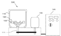
図1に本発明を適用できるトナー用外添剤の解砕装置の概略図を示す。
解砕装置100は、トナー用外添剤を収容する処理槽110、処理槽110の底部に回転可能に設けられた回転体としての処理羽根120を備えている。収容されるトナー用外添剤は、真密度が2,900kg/m3以上6,000kg/m3以下であり、二粒子間力が15pN以上200pN以下である。処理羽根120は、処理槽の水平断面の略中心を回転中心として水平に回転可能に設けられている。
Hereinafter, preferred embodiments of a method for pulverizing an external additive for toner and a method for producing a toner to which the present invention is applied will be described in detail.
[Crushing equipment]
FIG. 1 is a schematic diagram of a crusher for an external additive for toner to which the present invention can be applied.
The crushing
[処理槽]
図2に処理槽110の概略図を示す。
処理槽110は円柱状の内部空間を有し、平らな底部を持った円筒形の容器であり、中心軸が略鉛直となるように設置されていて、底部の略中心には処理羽根120を取り付けるための駆動軸111が備えられている。
処理槽110は高い強度を得られるという観点から鉄、SUS等の金属製が好ましく、内面は導電性の材質を用いるか内面の表面を導電加工することが好ましい。
[Treatment tank]
FIG. 2 shows a schematic diagram of the
The
The
処理槽110は、その外周部には必要に応じて冷却ジャケット112を備えている。
冷却ジャケット112は中空であり、IN側から冷却水などの冷媒を導入し、OUT側から排出できる構成である。
冷却ジャケット112に冷媒を通すことによって、処理中に昇温した材料の温度を調節することができる。
なお、図2に示す処理槽110の底部と側壁との接合部は効果的な清掃が容易なように曲面とすることが好ましい。
The
The cooling
By passing the coolant through the cooling
In addition, it is preferable that the junction part of the bottom part and side wall of the
図6に示す処理槽110の断面図において、処理槽110の内部の直径である内径をDとして、処理槽110の内部の高さをLとしたとき、本発明において、L/Dは0.8以上1.2以下である。
L/Dが0.8よりも小さい、すなわち内径Dに対して高さLが低い場合には、後述する回転体としての処理羽根120と処理槽110の上蓋との距離が近くなる。
その場合、解砕処理を行う際の転動作用によって舞い上げられたトナー用外添剤が処理槽110の上蓋等に付着しやすくなる。
In the cross-sectional view of the
When L / D is smaller than 0.8, that is, when the height L is low with respect to the inner diameter D, the distance between the
In this case, the external additive for toner that has been swollen by the rolling operation during the crushing process is likely to adhere to the upper lid or the like of the
またL/Dが1.2よりも大きい、すなわち内径Dに対して高さLが高い場合には、処理槽110の内部の表面積は相対的に大きくなる。
この場合には処理羽根120と処理槽110の上蓋との距離は遠くなるが、処理槽110の内部の表面積が大きいことから、やはり舞い上げられたトナー用外添剤が処理槽110の内部の表面に付着する量が多くなる。
したがって本発明におけるL/Dの範囲は0.8以上1.2以下である。
When L / D is larger than 1.2, that is, when the height L is higher than the inner diameter D, the surface area inside the
In this case, although the distance between the
Therefore, the range of L / D in the present invention is 0.8 or more and 1.2 or less.
[回転体]
図3、図4に処理羽根120の概略図を示す。図3は処理羽根120の全体構成をあらわす斜視図であり、図4(a)が平面図、図4(b)が正面図である。
本発明において処理羽根120は処理槽110の内部のトナー用外添剤と衝突してトナー用外添剤を解砕処理するものである。
処理羽根120は、円環状の処理羽根本体(回転体本体)121と、処理羽根本体121の外周面から径方向の外向きに突き出した複数の処理部122とが取り付けられて構成される。
さらにトナー用外添剤の転動を促進する制御部材123を設けることもできる。
処理羽根120は高い強度を得られるという観点から鉄、SUS等の金属製が好ましく、必要に応じて耐摩耗用にメッキやコーティングを施してもよい。
[Rotating body]
3 and 4 are schematic views of the
In the present invention, the
The
Further, a
The
[処理部の形状]
図5を用いて処理部122の形状について説明する。
図5(a)に示すように処理部122は処理羽根本体(回転体本体)121の外周面に取り付けられている。
処理羽根本体121が矢印方向に回転する時、斜線で示す部分が処理面124となり、トナー用外添剤に衝突する。
[Processing unit shape]
The shape of the
As shown in FIG. 5A, the
When the
処理面124はトナー用外添剤に衝突する目的からある程度の面積を持っていることが好ましいが平面である必然性は無く、部品の加工性や適用するトナー用外添剤に対する効果に応じて適宜選択することができる。
処理部122の形状は図5(a)に示す矩形に限られるものでなく、図5(b)に示すように角を面取り処理してあっても良く、図5(c)に示すように扇形であっても良い。
また板状に限られるものでなく、図5(d)に示すように処理面124とは反対側が処理面124とは異なる形状であっても良い。
The
The shape of the
Further, the shape is not limited to a plate shape, and the shape opposite to the
[処理部の高さ]
処理部122の高さについて説明する。
図6は処理槽110に処理羽根120を取り付けた状態を現す断面図である。
図6に示すように、処理槽110の内部の高さをL、処理槽110の底から処理部122の下端までの高さをB、上端までの高さをTとするとき、本発明において、B/Lは0.2以上かつT/Lは0.5以下である。
[Processing section height]
The height of the
FIG. 6 is a cross-sectional view showing a state where the
As shown in FIG. 6, when the height inside the
B/Lが0.2よりも小さい、つまりLに対してBが20%よりも低い位置にあると処理部122の回転によりトナー用外添剤を上方に舞い上げる効果が強くなり、処理部122の近傍でのトナー用外添剤の存在量が少なくなる場合が有る。
またT/Lが0.5よりも大きい、つまりLに対してTが50%よりも高い位置にある場合にはトナー用外添剤を50%よりも上まで舞い上げる手段が必要となるが、トナー用外添剤を積極的に舞い上げる手段を設けた場合に以下のような課題が有る。
When B / L is smaller than 0.2, that is, when B is lower than 20% with respect to L, the effect of raising the external additive for toner by the rotation of the
When T / L is larger than 0.5, that is, when T is higher than 50% with respect to L, means for raising the external additive for toner to more than 50% is necessary. When the means for positively raising the external additive for toner is provided, there are the following problems.
本発明に適用されるような真密度が高く、二粒子間力の高いトナー用外添剤を積極的に舞い上げると、トナー用外添剤が処理槽110の側壁の上側や上蓋に付着または堆積してしまう。
その結果、処理部122と衝突して解砕処理されるトナー用外添剤の量が実質的に少なくなってしまい効果が得られない。
前記のように、本発明の目的を達成するためには、B/Lが0.2以上かつT/Lが0.5以下であることが必要であり、B/Lが0.2%以上かつT/Lが0.32以下であることが好ましい。
When the toner external additive having a high true density and high interparticle force as applied to the present invention is positively raised, the toner external additive adheres to the upper side wall of the
As a result, the amount of the external additive for toner to be crushed by colliding with the
As described above, in order to achieve the object of the present invention, it is necessary that B / L is 0.2 or more and T / L is 0.5 or less, and B / L is 0.2% or more. And it is preferable that T / L is 0.32 or less.
[処理面の面積]
本発明における処理面の合計面積とは、図5に示すような処理面124の面積を全ての処理部122について合計した面積である。例えば、図5(a)に示す処理面124の面積がSaであり、処理羽根本体121が8個の処理部122を有する場合、
処理面の合計面積=8×Sa
となる。
処理槽110の中心軸を通る鉛直方向の断面の面積に対する処理面124の合計面積の割合には好適な範囲が存在する。
処理面124の合計面積の割合が3%以上であれば、処理面124がトナー用外添剤と衝突して解砕処理する効果が十分に得られる。
処理面124の合計面積の割合が20%以下であれば、処理面124の回転による作用によってトナー用外添剤を舞い上げる作用が強くなりすぎたりせず、前述の理由により解砕効果が小さくなることもない。
本発明の目的を達成するためには、処理槽110の中心軸を通る鉛直方向の断面の面積に対する処理面124の合計面積の割合が、3%以上20%以下であることが好ましく、7%以上15%以下であることがより好ましい。
[Area of treated surface]
The total area of the processing surfaces in the present invention is an area obtained by adding the areas of the processing surfaces 124 as shown in FIG. For example, when the area of the
Total area of treated surface = 8 × Sa
It becomes.
There is a suitable range for the ratio of the total area of the
If the ratio of the total area of the
If the ratio of the total area of the
In order to achieve the object of the present invention, the ratio of the total area of the
[転動を促進する制御部材]
本発明においてトナー用外添剤を処理部122に衝突させるためには処理槽110の内部でトナー用外添剤の転動を促進して処理部122に繰り返し衝突させることが効果的である。
図4に示す制御部材123は処理羽根120に取り付けられていて、処理部122よりも下側に設けられている。
制御部材123は処理羽根120における上側では駆動軸111から遠い側に設けられている。処理羽根120の下側、すなわち処理槽110の底部に近い側では制御部材123は駆動軸111に近い側に設けられていて図4に示すように斜めに取り付けられていることが好ましい。
[Control member that promotes rolling]
In the present invention, in order to cause the toner external additive to collide with the
The
The
処理槽110の内部でのトナー用外添剤の挙動として、基本的には処理羽根120の回転に伴って旋回するものであるが、真密度の高いトナー用外添剤において処理槽110の底部に近い程その旋回速度は遅くなる。
制御部材123を本発明のような構成とすることで、処理部122に近い領域ではトナー用外添剤の旋回速度を必要以上に速くしないようにしている。
さらに処理槽110の底部に近い領域でのトナー用外添剤を中心から外側へ押し出す効果を大きくすることができる。
その結果トナー用外添剤の転動を促進することが可能となる。
適用されるトナー用外添剤の特性に応じて制御部材123の形状は柱状やブレード状等を選択することが可能であり、制御部材123の数は2、4または6個等が選択可能である。
The behavior of the external additive for toner inside the
By adopting the configuration of the
Further, the effect of pushing the external additive for toner in the region near the bottom of the
As a result, it is possible to promote the rolling of the toner external additive.
The shape of the
[その他の部材]
その他の部材として処理羽根120よりも上方にはトナー用外添剤の転動を妨げる部材を設けないことが好ましい。トナー用外添剤の転動を妨げる部材を設けた場合には当該部材にトナー用外添剤が付着または堆積してしまう。
その結果、処理部122と衝突して解砕処理されるトナー用外添剤の量が実質的に少なくなってしまい効果が小さくなる場合が有る。
転動を妨げる部材としては例えばFMミキサ(日本コークス工業(株)製)におけるデフレクタ(規制板)やCOMPOSI(日本コークス工業(株)製)における衝突板がこれに相当する。
[Other parts]
As other members, it is preferable not to provide a member that prevents rolling of the toner external additive above the
As a result, the amount of the external additive for toner to be crushed by colliding with the
Examples of the member that prevents rolling include a deflector (regulation plate) in FM mixer (manufactured by Nippon Coke Industries, Ltd.) and a collision plate in COMPOSI (manufactured by Nippon Coke Industries, Ltd.).
[トナーの製造]
次に、本発明のトナー処理装置を用いたトナーの製造方法の一例について説明する。
トナー粒子の製造方法については、特に限定されず、従来公知の製造方法を用いることができ、重合法、粉砕法、乳化凝集法、溶融懸濁法等種々のトナー粒子に対して本発明を適用できる。
[Production of toner]
Next, an example of a toner manufacturing method using the toner processing apparatus of the present invention will be described.
The method for producing toner particles is not particularly limited, and a conventionally known production method can be used, and the present invention is applied to various toner particles such as a polymerization method, a pulverization method, an emulsion aggregation method, and a melt suspension method. it can.
[粉砕トナー粒子の製造方法]
ここでは、粉砕法を用いたトナーの製造手順について説明する。
原料混合工程では、トナー粒子を構成する材料として、結着樹脂、着色剤、及びワックス、並びに必要に応じて、荷電制御剤等の他の成分を所定量秤量して配合し、混合する。
混合装置の一例としては、スーパーミキサー((株)カワタ製)、FMミキサ、メカノハイブリッド(日本コークス工業(株)製)、ナウターミキサー(ホソカワミクロン(株)製)等が挙げられる。
[Production method of pulverized toner particles]
Here, a toner manufacturing procedure using a pulverization method will be described.
In the raw material mixing step, as a material constituting the toner particles, a binder resin, a colorant, a wax, and, if necessary, other components such as a charge control agent are weighed and mixed in a predetermined amount and mixed.
Examples of the mixing apparatus include a super mixer (manufactured by Kawata Co., Ltd.), an FM mixer, a mechano hybrid (manufactured by Nippon Coke Industries, Ltd.), a nauter mixer (manufactured by Hosokawa Micron Co., Ltd.), and the like.
次に、混合した材料を溶融混練して、結着樹脂中にワックス等を分散させる。その溶融混練工程では、加圧ニーダー、バンバリィミキサーの如きバッチ式練り機や、連続式の練り機を用いることができる。
連続生産できる優位性から、1軸又は2軸押出機が主流となっている。
例えば、KTK型2軸押出機((株)神戸製鋼所製)、TEM型2軸押出機(東芝機械(株)製)、PCM混練機((株)池貝製)、ニーデックス(日本コークス工業(株)製)が挙げられる。
Next, the mixed material is melt-kneaded to disperse wax or the like in the binder resin. In the melt-kneading step, a batch kneader such as a pressure kneader or a Banbury mixer, or a continuous kneader can be used.
Due to the advantage of continuous production, single-screw or twin-screw extruders are the mainstream.
For example, KTK type twin screw extruder (manufactured by Kobe Steel, Ltd.), TEM type twin screw extruder (manufactured by Toshiba Machine Co., Ltd.), PCM kneader (manufactured by Ikekai Co., Ltd.), Nidex (Nippon Coke Industries, Ltd.) Product).
更に、溶融混練することによって得られる樹脂組成物は、2本ロール等で圧延され、冷却工程で水などによって冷却してもよい。
ついで、樹脂組成物の冷却物は、粉砕工程で所望の粒径にまで粉砕される。
粉砕工程では、クラッシャー、ハンマーミル、の如き粉砕機で粗粉砕した後、更に、クリプトロンシステム((株)アーステクニカ製)、ターボ・ミル(フロイント・ターボ(株)製)等による微粉砕機で微粉砕する。
その後、必要に応じて慣性分級方式のエルボジェット(日鉄鉱業(株)製)、遠心力分級方式のTSPセパレータ(ホソカワミクロン(株)製)、ファカルティ(ホソカワミクロン(株)製)の如き分級機や篩分機を用いて分級し、トナー粒子を得る。
Furthermore, the resin composition obtained by melt-kneading may be rolled with two rolls or the like and cooled with water or the like in the cooling step.
Next, the cooled product of the resin composition is pulverized to a desired particle size in the pulverization step.
In the pulverization process, after coarse pulverization with a crusher such as a crusher or hammer mill, a fine pulverizer using a kryptron system (manufactured by Earth Technica), turbo mill (manufactured by Freund Turbo), etc. Crush finely.
After that, if necessary, classifiers such as inertial class elbow jet (manufactured by Nippon Steel Mining Co., Ltd.), centrifugal classifier TSP separator (manufactured by Hosokawa Micron Co., Ltd.), Faculty (manufactured by Hosokawa Micron Co., Ltd.) Classification is performed using a sieving machine to obtain toner particles.
[重合トナー粒子の製造方法]
重合法としては懸濁重合法・界面重合法・分散重合法の如き、親水性媒体中で直接トナーを製造する方法が挙げられる。
以下に懸濁重合法を用いたトナーの製造手順について説明する。
懸濁重合法は、重合性単量体、着色剤等を有する重合性単量体組成物を水系媒体中に分散して、該重合性単量体組成物の液滴を製造する造粒工程、該液滴中の該重合性単量体を重合する重合工程を少なくとも経ることによりトナー母粒子を製造する重合法である。
そして、本発明のトナーを製造する場合には、重合性単量体組成物中に、低分子量樹脂を含有させることが好ましい。
[Method for producing polymerized toner particles]
Examples of the polymerization method include a method of directly producing a toner in a hydrophilic medium such as a suspension polymerization method, an interfacial polymerization method, and a dispersion polymerization method.
A procedure for producing a toner using the suspension polymerization method will be described below.
The suspension polymerization method is a granulation step in which a polymerizable monomer composition having a polymerizable monomer, a colorant and the like is dispersed in an aqueous medium to produce droplets of the polymerizable monomer composition. In this polymerization method, toner base particles are produced through at least a polymerization step of polymerizing the polymerizable monomer in the droplets.
And when manufacturing the toner of this invention, it is preferable to contain low molecular weight resin in a polymerizable monomer composition.
本発明のトナーは、コア部とシェル部を少なくとも有するトナー母粒子を有するトナーであることが好ましい。該トナー母粒子には、コア部を覆うようにシェル部が存在している。このような構造をとることによりコア部のトナー粒子表面への滲出による帯電不良やブロッキングを防ぐことができる。また、さらにシェル部の表面上にはシェル部とは樹脂組成の違う表層部が存在するものがより好ましい。この表層部が存在することにより環境安定性、耐久性、耐ブロッキング性をより向上させることができる。 The toner of the present invention is preferably a toner having toner base particles having at least a core part and a shell part. The toner base particles have a shell portion so as to cover the core portion. By adopting such a structure, it is possible to prevent poor charging and blocking due to leaching of the core part to the toner particle surface. Further, it is more preferable that a surface layer portion having a resin composition different from that of the shell portion is present on the surface of the shell portion. The presence of this surface layer portion can further improve environmental stability, durability, and blocking resistance.
本発明のトナー母粒子を生成するために使用することができる重合性単量体として好ましいものに、ビニル系重合性単量体を挙げることができる。例えばスチレン;α−メチルスチレン、β−メチルスチレン、o−メチルスチレン、m−メチルスチレン、p−メチルスチレン、2,4−ジメチルスチレン、p−n−ブチルスチレン、p−tert−ブチルスチレン、p−n−ヘキシルスチレン、p−n−オクチル、p−n−ノニルスチレン、p−n−デシルスチレン、p−n−ドデシルスチレン、p−メトキシスチレン、p−フェニルスチレンの如きスチレン誘導体;メチルアクリレート、エチルアクリレート、n−プロピルアクリレート、iso−プロピルアクリレート、n−ブチルアクリレート、iso−ブチルアクリレート、tert−ブチルアクリレート、n−アミルアクリレート、n−ヘキシルアクリレート、2−エチルヘキシルアクリレート、n−オクチルアクリレート、n−ノニルアクリレート、シクロヘキシルアクリレート、ベンジルアクリレート、ジメチルフォスフェートエチルアクリレート、ジエチルフォスフェートエチルアクリレート、ジブチルフォスフェートエチルアクリレート、2−ベンゾイルオキシエチルアクリレートの如きアクリル系重合性単量体;メチルメタクリレート、エチルメタクリレート、n−プロピルメタクリレート、iso−プロピルメタクリレート、n−ブチルメタクリレート、iso−ブチルメタクリレート、tert−ブチルメタクリレート、n−アミルメタクリレート、n−ヘキシルメタクリレート、2−エチルヘキシルメタクリレート、n−オクチルメタクリレート、n−ノニルメタクリレート、ジエチルフォスフェートエチルメタクリレート、ジブチルフォスフェートエチルメタクリレートの如きメタクリル系重合性単量体;メチレン脂肪族モノカルボン酸エステル類;酢酸ビニル、プロピオン酸ビニル、ベンゾエ酸ビニル、酪酸ビニル、安息香酸ビニル、蟻酸ビニルの如きビニルエステル;ビニルメチルエーテル、ビニルエチルエーテル、ビニルイソブチルエーテルの如きビニルエーテル;ビニルメチルケトン、ビニルヘキシルケトン、ビニルイソプロピルケトンの如きビニルケトンが挙げられる。 Preferred examples of the polymerizable monomer that can be used to produce the toner base particles of the present invention include a vinyl polymerizable monomer. For example, styrene; α-methylstyrene, β-methylstyrene, o-methylstyrene, m-methylstyrene, p-methylstyrene, 2,4-dimethylstyrene, pn-butylstyrene, p-tert-butylstyrene, p Styrene derivatives such as -n-hexyl styrene, pn-octyl, pn-nonyl styrene, pn-decyl styrene, pn-dodecyl styrene, p-methoxy styrene, p-phenyl styrene; methyl acrylate, Ethyl acrylate, n-propyl acrylate, iso-propyl acrylate, n-butyl acrylate, iso-butyl acrylate, tert-butyl acrylate, n-amyl acrylate, n-hexyl acrylate, 2-ethylhexyl acrylate, n-octyl acrylate, n- Acrylic polymerizable monomers such as nonyl acrylate, cyclohexyl acrylate, benzyl acrylate, dimethyl phosphate ethyl acrylate, diethyl phosphate ethyl acrylate, dibutyl phosphate ethyl acrylate, 2-benzoyloxyethyl acrylate; methyl methacrylate, ethyl methacrylate, n -Propyl methacrylate, iso-propyl methacrylate, n-butyl methacrylate, iso-butyl methacrylate, tert-butyl methacrylate, n-amyl methacrylate, n-hexyl methacrylate, 2-ethylhexyl methacrylate, n-octyl methacrylate, n-nonyl methacrylate, diethyl Phosphate ethyl methacrylate, dibutyl phosphate Methacrylic polymerizable monomers such as methyl methacrylate; methylene aliphatic monocarboxylic acid esters; vinyl acetate, vinyl propionate, vinyl benzoate, vinyl butyrate, vinyl benzoate, vinyl formate; vinyl methyl ether; And vinyl ethers such as vinyl ethyl ether and vinyl isobutyl ether; vinyl ketones such as vinyl methyl ketone, vinyl hexyl ketone and vinyl isopropyl ketone.
シェル部は、これらのビニル系重合性単量体から形成されるビニル系重合体や添加したビニル系重合体によって構成される。これらのビニル系重合体の中でも、内部又は中心部を主に形成しているワックスを効率的に覆うという点から、スチレン重合体若しくはスチレン−アクリル共重合体或いはスチレン−メタクリル共重合体が好ましい。 The shell portion is composed of a vinyl polymer formed from these vinyl polymerizable monomers or an added vinyl polymer. Among these vinyl polymers, a styrene polymer, a styrene-acrylic copolymer, or a styrene-methacrylic copolymer is preferable from the viewpoint of efficiently covering the wax mainly forming the inside or the central portion.
本発明のトナーのコア部を構成する材料としてはワックスが好ましい。
本発明に係わるトナーに使用可能なワックス成分としては、パラフィンワックス、マイクロクリスタリンワックス、ペトロラタムの如き石油系ワックス及びその誘導体、モンタンワックス及びその誘導体、フィッシャートロプシュ法による炭化水素ワックス及びその誘導体、ポリエチレン、ポリプロピレンの如きポリオレフィンワックス及びその誘導体、カルナバワックス、キャンデリラワックスの如き天然ワックス及びその誘導体などで、誘導体には酸化物や、ビニル系モノマーとのブロック共重合物、グラフト変性物を含む。さらには、高級脂肪族アルコール、ステアリン酸、パルミチン酸等の脂肪酸、あるいはその化合物、酸アミドワックス、エステルワックス、ケトン、硬化ヒマシ油及びその誘導体、植物系ワックス、動物性ワックス、シリコーン樹脂も使用できる。
The material constituting the core of the toner of the present invention is preferably wax.
The wax component usable in the toner according to the present invention includes paraffin wax, microcrystalline wax, petroleum wax such as petrolatum and derivatives thereof, montan wax and derivatives thereof, hydrocarbon wax and derivatives thereof according to the Fischer-Tropsch method, polyethylene, Polyolefin waxes such as polypropylene and derivatives thereof, natural waxes such as carnauba wax and candelilla wax and derivatives thereof, and the like include oxides, block copolymers with vinyl monomers, and graft modified products. Furthermore, fatty acids such as higher aliphatic alcohols, stearic acid and palmitic acid, or compounds thereof, acid amide waxes, ester waxes, ketones, hydrogenated castor oil and derivatives thereof, plant-based waxes, animal waxes, and silicone resins can also be used. .
[トナー用外添剤の解砕処理]
このようにして得られた、トナー粒子の表面に外添剤を外添処理するに先だって、トナー用外添剤に対して解砕処理を施す装置として図1に示す本発明の解砕装置100を用いる。
解砕装置100は円筒形の処理槽110が略鉛直に設置されていて、処理槽110の底部の略中心に設けた駆動軸111に処理羽根120が取り付けられている。
処理羽根120の下方には他の回転部材は取り付けない。
処理部122の取り付け高さは、処理槽110の高さLに対して
処理部122の下端の高さBが20.0%以上となり、
処理部122の上端の高さTが50.0%以下となるようにする。
[Crushing of external additive for toner]
The external
In the crushing
No other rotating member is attached below the
The mounting height of the
The height T of the upper end of the
処理羽根120の回転周速を後述する所定の範囲内で設定する。
次に処理槽110の上蓋を開け、予め計量しておいたトナー用外添剤を投入する。投入後上蓋を閉め、以下に記載する回転周速で、処理羽根120を回転させる。
所望の時間処理を行った後、排出弁(図示しない)を開き、処理槽110からトナー用外添剤を取り出す。
The rotational peripheral speed of the
Next, the upper lid of the
After processing for a desired time, a discharge valve (not shown) is opened, and the toner external additive is taken out from the
処理羽根120の回転周速や、混合時間は、トナー用外添剤を解砕処理するためにはある程度高い周速を使用することが好ましい。
具体的には、処理部の先端における周速度は30.0m/秒以上であることが好ましく、40.0m/秒以上であることがより好ましい。
混合時間は0.5分以上、60分以下の範囲で調整することが好ましい。
As for the rotational peripheral speed of the
Specifically, the peripheral speed at the tip of the processing unit is preferably 30.0 m / second or more, and more preferably 40.0 m / second or more.
The mixing time is preferably adjusted in the range of 0.5 minutes to 60 minutes.
[外添処理]
トナー粒子の表面に、解砕処理されたトナー用外添剤を被覆させる処理装置として、例えば図10に示すトナー処理装置200を用いる。
トナー処理装置200は処理槽210と処理槽210の底部に回転可能に取り付けられた下羽根220、上羽根230、処理槽210の上部に固定された規制板240で構成されている。
制御部260には駆動スイッチ、回転数調整器、温度表示器等が備えられていて、駆動スイッチによってモーター250が回転することにより設定された回転数で下羽根220、上羽根230が回転するものである。
[External processing]
For example, a
The
The
運転方法は以下の通りである。
図10に示すトナー処理装置200の下羽根220、上羽根230の回転周速を後記する所定の範囲内で設定する。
次に、処理槽210の上蓋を開け、予め計量しておいたトナー粒子及び解砕処理されたトナー用外添剤を含む被処理物を投入する。投入後上蓋を閉め、以下に記載する回転周速で、下羽根220、上羽根230を回転させる。
The operation method is as follows.
The rotational peripheral speeds of the
Next, the upper lid of the
更に、下羽根220、上羽根230を回転中、冷水発生手段からの冷水を冷却ジャケット211に供給することで、処理槽210内の材料温度を、トナーに含有される樹脂成分のガラス転移点(Tg)以下に調整する。
所望の時間処理を行った後、排出弁(図示しない)を開き、処理槽210からトナーを取り出す。その後、35μmから75μm開口程度のメッシュに通し、粗大粒子を除去し、トナーを得る。
Further, while the
After processing for a desired time, a discharge valve (not shown) is opened and the toner is taken out from the
下羽根220、上羽根230の回転周速や、混合時間は、処理中の材料温度がトナーに含有される樹脂成分のガラス転移点(Tg)以下となる範囲に調整することが好ましい。
具体的には、下羽根220、上羽根230の回転周速の最大周速は10.0m/秒以上、150.0m/秒以下であることが好ましく、30.0m/秒以上、70.0m/秒以下であることがより好ましい。
混合時間は0.5分以上、60分以下の範囲で調整することが好ましい。
トナー粒子とトナー用外添剤を処理させる工程は、1段階で行っても、2段階以上の多段階で行ってもよく、それぞれの段階で用いる混合条件及びトナー粒子の配合等は、同一であっても異なっていても良い。
The rotational peripheral speed and mixing time of the
Specifically, the maximum peripheral speed of the rotational peripheral speed of the
The mixing time is preferably adjusted in the range of 0.5 minutes to 60 minutes.
The process of treating the toner particles and the toner external additive may be performed in one step or in two or more steps, and the mixing conditions and the blending of the toner particles used in each step are the same. It can be different.
[結着樹脂]
次に、本発明に用いられる、トナーに関して説明する。トナーとしては、公知のものが使用でき、粉砕法、重合法、乳化凝集法、溶解懸濁法等のいずれの方法で製造されたものであってもよい。
トナーを構成する結着樹脂としては、通常トナーに用いられ樹脂を使用することができる。以下のようなものが挙げられる。
ポリスチレン;ポリ−p−クロルスチレン、ポリビニルトルエンの如きスチレン置換体の単重合体;スチレン−p−クロルスチレン共重合体。
[Binder resin]
Next, the toner used in the present invention will be described. As the toner, a known toner can be used, and the toner may be produced by any method such as a pulverization method, a polymerization method, an emulsion aggregation method, and a dissolution suspension method.
As the binder resin constituting the toner, a resin that is usually used for toner can be used. The following are listed.
Polystyrene; homopolymer of styrene-substituted product such as poly-p-chlorostyrene and polyvinyltoluene; styrene-p-chlorostyrene copolymer.
更に、スチレン−ビニルトルエン共重合体、スチレン−ビニルナフタリン共重合体、スチレン−アクリル酸エステル共重合体、スチレン−メタクリル酸エステル共重合体、スチレン−α−クロルメタクリル酸メチル共重合体が挙げられる。
更に、スチレン−アクリロニトリル共重合体、スチレン−ビニルメチルエーテル共重合体、スチレン−ビニルエチルエーテル共重合体、スチレン−ビニルメチルケトン共重合体、スチレン−ブタジエン共重合体が挙げられる。
Furthermore, a styrene-vinyl toluene copolymer, a styrene-vinyl naphthalene copolymer, a styrene-acrylic acid ester copolymer, a styrene-methacrylic acid ester copolymer, and a styrene-α-chloromethyl methacrylate copolymer are exemplified. .
Furthermore, a styrene-acrylonitrile copolymer, a styrene-vinyl methyl ether copolymer, a styrene-vinyl ethyl ether copolymer, a styrene-vinyl methyl ketone copolymer, and a styrene-butadiene copolymer are exemplified.
更に、スチレン−イソプレン共重合体、スチレン−アクリロニトリル−インデン共重合体の如きスチレン系共重合体;ポリ塩化ビニル、フェノール樹脂、天然変性フェノール樹脂、天然樹脂変性マレイン酸樹脂、アクリル樹脂が挙げられる。
更に、メタクリル樹脂、ポリ酢酸ビニル、シリコーン樹脂、ポリエステル樹脂、ポリウレタン、ポリアミド樹脂、フラン樹脂、エポキシ樹脂、キシレン樹脂、ポリビニルブチラール、テルペン樹脂、クマロンインデン樹脂及び石油系樹脂が挙げられる。
Further, styrene copolymers such as styrene-isoprene copolymer and styrene-acrylonitrile-indene copolymer; polyvinyl chloride, phenol resin, natural modified phenol resin, natural resin modified maleic acid resin, and acrylic resin.
Further examples include methacrylic resin, polyvinyl acetate, silicone resin, polyester resin, polyurethane, polyamide resin, furan resin, epoxy resin, xylene resin, polyvinyl butyral, terpene resin, coumarone indene resin, and petroleum resin.
トナーの物性のうち、結着樹脂に起因するものとしては、テトラヒドロフラン(THF)可溶分のゲルパーミエーションクロマトグラフィ(GPC)により測定される分子量分布は以下のものが好ましい。
すなわち、分子量2,000以上50,000以下の領域に少なくとも一つのピークを有し、分子量1,000以上30,000以下の成分が50%以上90%以下存在する場合がより好ましい。
Among the physical properties of the toner, the molecular weight distribution measured by gel permeation chromatography (GPC) soluble in tetrahydrofuran (THF) is preferably as follows due to the binder resin.
That is, it is more preferable that a component having at least one peak in a molecular weight range of 2,000 to 50,000 and having a molecular weight of 1,000 to 30,000 is present in an amount of 50% to 90%.
結着樹脂のガラス転移点(Tg)は30℃以上60℃以下であることが好ましく、40℃以上60℃以下であることがより好ましい。
ガラス転移点(Tg)が上記の範囲内であれば、トナーの耐久性に優れると共に、高温多湿環境下におけるトナー粒子同士の凝集が抑制される。
The glass transition point (Tg) of the binder resin is preferably 30 ° C. or higher and 60 ° C. or lower, and more preferably 40 ° C. or higher and 60 ° C. or lower.
When the glass transition point (Tg) is within the above range, the durability of the toner is excellent and aggregation of the toner particles in a high temperature and high humidity environment is suppressed.
[ワックス]
本発明に用いられるトナーにおいては、定着時の定着部材からの離型性の向上、定着性の向上の点から次のようなワックスがトナー粒子の材料として用いられる。
ワックスとしては、パラフィンワックス及びその誘導体、マイクロクリスタリンワックス及びその誘導体、フィッシャートロプシュワックス及びその誘導体、ポリオレフィンワックス及びその誘導体、カルナバワックス及びその誘導体が挙げられる。
[wax]
In the toner used in the present invention, the following wax is used as a material for the toner particles from the viewpoint of improving releasability from the fixing member during fixing and improving fixability.
Examples of the wax include paraffin wax and derivatives thereof, microcrystalline wax and derivatives thereof, Fischer-Tropsch wax and derivatives thereof, polyolefin wax and derivatives thereof, and carnauba wax and derivatives thereof.
これらのワックスの誘導体として、酸化物や、ビニル系モノマーとのブロック共重合物、グラフト変性物を含む。
その他のワックスとして、アルコール、脂肪酸、酸アミド、エステル、ケトン、硬化ヒマシ油及びその誘導体、植物系ワックス、動物性ワックス、鉱物系ワックス、ペトロラクタムが挙げられる。
Derivatives of these waxes include oxides, block copolymers with vinyl monomers, and graft modified products.
Examples of other waxes include alcohols, fatty acids, acid amides, esters, ketones, hydrogenated castor oil and derivatives thereof, plant waxes, animal waxes, mineral waxes, and petrolactam.
[荷電制御剤]
本発明に用いられるトナーにおいては、トナー粒子の帯電量及び帯電量分布を制御するために、荷電制御剤をトナー粒子に配合(内添)、又はトナー粒子と混合(外添)して用いることが好ましい。
トナーを負荷電性に制御するための負荷電制御剤としては、有機金属錯体、キレート化合物が挙げられる。有機金属錯体としては、モノアゾ金属錯体、アセチルアセトン金属錯体、芳香族ハイドロキシカルボン酸金属錯体、芳香族ジカルボン酸金属錯体が挙げられる。
[Charge control agent]
In the toner used in the present invention, in order to control the charge amount and charge amount distribution of the toner particles, a charge control agent is blended with the toner particles (internal addition) or mixed with the toner particles (external addition). Is preferred.
Examples of the negative charge control agent for controlling the toner to be negatively charged include organometallic complexes and chelate compounds. Examples of the organometallic complex include a monoazo metal complex, an acetylacetone metal complex, an aromatic hydroxycarboxylic acid metal complex, and an aromatic dicarboxylic acid metal complex.
更に、負荷電制御剤としては、芳香族ハイドロキシカルボン酸、芳香族モノカルボン酸及び芳香族ポリカルボン酸及びその金属塩;芳香族ハイドロキシカルボン酸、芳香族モノカルボン酸及び芳香族ポリカルボン酸の無水物が挙げられる。
更に、芳香族ハイドロキシカルボン酸、芳香族モノカルボン酸及び芳香族ポリカルボン酸のエステル化合物、ビスフェノールの如きフェノール誘導体が挙げられる。
Further, the negative charge control agent includes aromatic hydroxycarboxylic acid, aromatic monocarboxylic acid and aromatic polycarboxylic acid and metal salts thereof; anhydrous hydroxycarboxylic acid, aromatic monocarboxylic acid and aromatic polycarboxylic acid anhydride. Things.
Furthermore, ester compounds of aromatic hydroxycarboxylic acid, aromatic monocarboxylic acid and aromatic polycarboxylic acid, and phenol derivatives such as bisphenol are included.
トナーを正荷電性に制御するための正荷電制御剤としては、ニグロシン及び脂肪酸金属塩によるニグロシンの変性物;トリブチルベンジルアンモニウム−1−ヒドロキシ−4−ナフトスルホン酸塩が挙げられる。
更に、テトラブチルアンモニウムテトラフルオロボレートの如き四級アンモニウム塩及びこれらのレーキ顔料;トリブチルベンジルホスホニウム−1−ヒドロキシ−4−ナフトスルホン酸塩が挙げられる。
更に、テトラブチルホスホニウムテトラフルオロボレートの如きホスホニウム塩及びこれらのレーキ顔料;トリフェニルメタン染料及びこれらのレーキ顔料(レーキ化剤としては、燐タングステン酸が挙げられる。
更に、燐モリブデン酸、燐タングステンモリブデン酸、タンニン酸、ラウリン酸、没食子酸、フェリシアン化物、フェロシアン化物等);高級脂肪酸の金属塩が挙げられる。
Examples of the positive charge control agent for controlling the toner to be positively charged include nigrosine and a modified product of nigrosine by a fatty acid metal salt; tributylbenzylammonium-1-hydroxy-4-naphthosulfonate.
Further examples include quaternary ammonium salts such as tetrabutylammonium tetrafluoroborate and lake pigments thereof; tributylbenzylphosphonium-1-hydroxy-4-naphthosulfonate.
Furthermore, phosphonium salts such as tetrabutylphosphonium tetrafluoroborate and lake lake pigments thereof; triphenylmethane dyes and lake lake pigments (the rake agent includes phosphotungstic acid.
Furthermore, phosphomolybdic acid, phosphotungstic molybdic acid, tannic acid, lauric acid, gallic acid, ferricyanide, ferrocyanide, etc.); higher fatty acid metal salts.
これらの荷電制御剤は、単独で又は二種類以上を組み合わせて用いることができる。また、電荷制御樹脂も用いることができ、上記の荷電制御剤と併用することもできる。
上記した荷電制御剤は微粒子状で用いることが好ましい。これらの荷電制御剤をトナー粒子に内添する場合は、結着樹脂100.0質量部に対して0.1質量部以上20.0質量部以下をトナー粒子に添加することが好ましい。
These charge control agents can be used alone or in combination of two or more. Moreover, charge control resin can also be used and can also be used together with said charge control agent.
The above charge control agent is preferably used in the form of fine particles. When these charge control agents are internally added to the toner particles, it is preferable to add 0.1 parts by mass or more and 20.0 parts by mass or less to the toner particles with respect to 100.0 parts by mass of the binder resin.
[着色剤]
本発明に用いられるトナーにおいては、トナー粒子の材料として、従来知られている種々の着色剤を用いることができる。
黒色着色剤としては、マグネタイト、カーボンブラック、以下に示すイエロー着色剤、マゼンタ着色剤及びシアン着色剤の如き有彩色着色剤によって黒色に調色されるように組み合わせたものが用いられる。特に染料やカーボンブラックは、重合阻害性を有しているものが多いので使用の際に注意を要する。
[Colorant]
In the toner used in the present invention, conventionally known various colorants can be used as the toner particle material.
As the black colorant, those combined so as to be adjusted to black by a chromatic colorant such as magnetite, carbon black, the following yellow colorant, magenta colorant and cyan colorant are used. In particular, since dyes and carbon black have many polymerization-inhibiting properties, care must be taken when using them.
イエロー着色剤としては、縮合アゾ化合物、イソインドリノン化合物、アンスラキノン化合物、アゾ金属錯体、メチン化合物、アリルアミド化合物に代表される化合物が用いられる。
具体的には、C.I.ピグメントイエロー12、13、14、15、17、62、74、83、93、94、95、97、109、110、111が挙げられる。
更に、120、127、128、129、147、155、162、168、174、176、180、181、185、191が挙げられる。
As the yellow colorant, compounds represented by condensed azo compounds, isoindolinone compounds, anthraquinone compounds, azo metal complexes, methine compounds, and allylamide compounds are used.
Specifically, C.I. I. Pigment yellow 12, 13, 14, 15, 17, 62, 74, 83, 93, 94, 95, 97, 109, 110, 111.
Furthermore, 120, 127, 128, 129, 147, 155, 162, 168, 174, 176, 180, 181, 185, 191 may be mentioned.
マゼンタ着色剤としては、縮合アゾ化合物、ジケトピロロピロール化合物、アンスラキノン、キナクリドン化合物、塩基染料レーキ化合物、ナフトール化合物、ベンズイミダゾロン化合物、チオインジゴ化合物、ペリレン化合物が用いられる。
具体的には、C.I.ピグメントレッド2、3、5、6、7、23、31、48;2、48;3、48;4、57;1、81;1、122が挙げられる。
更に、144、146、150、166、169、177、184、185、202、206、220、221、238、254が挙げられる。
As the magenta colorant, condensed azo compounds, diketopyrrolopyrrole compounds, anthraquinones, quinacridone compounds, basic dye lake compounds, naphthol compounds, benzimidazolone compounds, thioindigo compounds, and perylene compounds are used.
Specifically, C.I. I. Pigment red 2, 3, 5, 6, 7, 23, 31, 48; 2, 48; 3, 48; 4, 57; 1, 81;
Furthermore, 144, 146, 150, 166, 169, 177, 184, 185, 202, 206, 220, 221, 238, 254 may be mentioned.
シアン着色剤としては、銅フタロシアニン化合物及びその誘導体、アンスラキノン化合物、塩基染料レーキ化合物が用いられる。
具体的には、C.I.ピグメントブルー1、7、15、15:1、15:2、15:3、15:4、60、62、66が挙げられる。
これらの着色剤は、単独又は混合し更には固溶体の状態で用いることができる。
As the cyan colorant, copper phthalocyanine compounds and derivatives thereof, anthraquinone compounds, basic dye lake compounds are used.
Specifically, C.I. I. Pigment blue 1, 7, 15, 15: 1, 15: 2, 15: 3, 15: 4, 60, 62, 66.
These colorants can be used alone or in combination and further in the form of a solid solution.
本発明において、着色剤は、色相角、彩度、明度、耐候性、OHP透明性、トナー中への分散性を考慮して選択される。
これらの有彩色の非磁性の着色剤は、結着樹脂100質量部に対し総量で1.0質量部以上20.0質量部以下がトナー粒子中に含有される。
さらに本発明のトナーは、着色剤として磁性材料を含有させ磁性トナーとすることも可能である。
In the present invention, the colorant is selected in consideration of hue angle, saturation, brightness, weather resistance, OHP transparency, and dispersibility in the toner.
These chromatic non-magnetic colorants are contained in the toner particles in a total amount of 1.0 to 20.0 parts by mass with respect to 100 parts by mass of the binder resin.
Furthermore, the toner of the present invention may be a magnetic toner containing a magnetic material as a colorant.
この場合、磁性材料は着色剤の役割をかねることもできる。磁性材料としては、マグネタイト、ヘマタイト、フェライト如きの酸化鉄;鉄、コバルト、ニッケルの如き金属或いはこれらの金属のアルミニウム、コバルト、銅、鉛、マグネシウム、スズ、亜鉛、アンチモン、ベリリウム、ビスマス、カドミウム、カルシウム、マンガン、セレン、チタン、タングステン、バナジウムの如き金属の合金及びその混合物が挙げられる。
上記磁性体は、より好ましくは、表面改質された磁性体が好ましい。
重合法により磁性トナーを調整する場合には、重合阻害のない物質である表面改質剤により、疎水化処理を施したものが好ましい。
In this case, the magnetic material can also serve as a colorant. Magnetic materials include iron oxides such as magnetite, hematite and ferrite; metals such as iron, cobalt and nickel or aluminum, cobalt, copper, lead, magnesium, tin, zinc, antimony, beryllium, bismuth, cadmium, Examples include alloys of metals such as calcium, manganese, selenium, titanium, tungsten, vanadium, and mixtures thereof.
The magnetic material is more preferably a surface-modified magnetic material.
When a magnetic toner is prepared by a polymerization method, it is preferable to apply a hydrophobic treatment with a surface modifier, which is a substance that does not inhibit polymerization.
このような表面改質剤としては、例えばシランカップリング剤、チタンカップリング剤を挙げることができる。これらの磁性体は個数平均粒径が2μm以下が好ましく、0.1〜0.5μmのものがさらに好ましい。
トナー粒子中に含有させる量としては、重合性単量体又は結着樹脂100質量部に対し20〜200質量部、特に好ましくは結着樹脂100質量部に対し40質量部以上150質量部以下が良い。
Examples of such surface modifiers include silane coupling agents and titanium coupling agents. These magnetic materials preferably have a number average particle diameter of 2 μm or less, more preferably 0.1 to 0.5 μm.
The amount to be contained in the toner particles is 20 to 200 parts by mass, particularly preferably 40 to 150 parts by mass with respect to 100 parts by mass of the binder monomer or the polymerizable monomer or binder resin. good.
[外添剤]
本発明において解砕処理したトナー用外添剤に加えて、酸化チタン、酸化アルミナ、及びシリカ微粒子のいずれかを添加しても構わない。
前記外添剤に含まれる微粒子の表面は、疎水化処理をされていることが好ましい。
疎水化処理は、各種チタンカップリング剤、シランカップリング剤の如きカップリング剤;脂肪酸及びその金属塩;シリコーンオイル;またはそれらの組み合わせによってなされることが好ましい。
[External additive]
In addition to the pulverized toner external additive in the present invention, any of titanium oxide, alumina oxide, and silica fine particles may be added.
The surface of the fine particles contained in the external additive is preferably subjected to a hydrophobic treatment.
The hydrophobizing treatment is preferably performed by a coupling agent such as various titanium coupling agents and silane coupling agents; fatty acids and metal salts thereof; silicone oils; or a combination thereof.
本発明において解砕処理したトナー用外添剤を含めた外添剤のトナー中における含有量は、0.1質量部以上10.0質量部以下であることが好ましく、0.5質量部以上8.0質量部以下であることがより好ましい。また外添剤は、複数種の微粒子の組み合わせでもよい。
本発明を適用したトナーと磁性キャリアを混合して二成分系現像剤を調製する場合、その混合比率は現像剤中のトナー濃度として、2質量%以上15質量%以下、好ましくは4質量%以上13質量%以下にすると通常良好な結果が得られる。
以下、本発明におけるトナー等の各種物性の測定法について説明する。
In the present invention, the content of the external additives including the external additive for the toner crushed in the toner is preferably 0.1 parts by mass or more and 10.0 parts by mass or less, and 0.5 parts by mass or more. It is more preferably 8.0 parts by mass or less. The external additive may be a combination of a plurality of types of fine particles.
When a two-component developer is prepared by mixing the toner to which the present invention is applied and a magnetic carrier, the mixing ratio is 2% by mass or more and 15% by mass or less, preferably 4% by mass or more, as the toner concentration in the developer. When the content is 13% by mass or less, good results are usually obtained.
Hereinafter, methods for measuring various physical properties of the toner and the like in the present invention will be described.
[トナーの重量平均粒径(D4)の測定方法]
トナーの重量平均粒径(D4)は、以下のようにして算出する。
測定装置としては、100μmのアパーチャーチューブを備えた細孔電気抵抗法による精密粒度分布測定装置「コールター・カウンター Multisizer 3」(登録商標、ベックマン・コールター(株)製)を用いる。
測定条件の設定及び測定データの解析は、付属の専用ソフト「ベックマン・コールター Multisizer 3 Version3.51」(ベックマン・コールター(株)製)を用いる。なお、測定は実効測定チャンネル数2万5千チャンネルで行う。
測定に使用する電解水溶液は、特級塩化ナトリウムをイオン交換水に溶解して濃度が1質量%となるようにしたもの、例えば、「ISOTON II」(ベックマン・コールター(株)製)を用いることができる。
[Method for Measuring Weight Average Particle Size (D4) of Toner]
The weight average particle diameter (D4) of the toner is calculated as follows.
As a measuring device, a precise particle size distribution measuring device “Coulter Counter Multisizer 3” (registered trademark, manufactured by Beckman Coulter, Inc.) using a pore electrical resistance method provided with a 100 μm aperture tube is used.
For setting of measurement conditions and analysis of measurement data, attached dedicated software “Beckman Coulter Multisizer 3 Version 3.51” (manufactured by Beckman Coulter, Inc.) is used. The measurement is performed with 25,000 effective measurement channels.
As the electrolytic aqueous solution used for the measurement, a special grade sodium chloride is dissolved in ion-exchanged water so that the concentration becomes 1% by mass, for example, “ISOTON II” (manufactured by Beckman Coulter, Inc.) is used. it can.
なお、測定、解析を行う前に、以下のように専用ソフトの設定を行う。
専用ソフトの「標準測定方法(SOM)を変更」画面において、コントロールモードの総カウント数を50,000粒子に設定し、測定回数を1回、Kd値は「標準粒子10.0μm」(ベックマン・コールター(株)製)を用いて得られた値を設定する。
「閾値/ノイズレベルの測定ボタン」を押すことで、閾値とノイズレベルを自動設定する。また、カレントを1600μAに、ゲインを2に、電解液をISOTON IIに設定し、「測定後のアパーチャーチューブのフラッシュ」にチェックを入れる。
専用ソフトの「パルスから粒径への変換設定」画面において、ビン間隔を対数粒径に、粒径ビンを256粒径ビンに、粒径範囲を2μmから60μmまでに設定する。
Prior to measurement and analysis, the dedicated software is set as follows.
On the “Change Standard Measurement Method (SOM)” screen of the dedicated software, set the total count in the control mode to 50,000 particles, set the number of measurements once, and set the Kd value to “standard particles 10.0 μm” (Beckman The value obtained using Coulter Co.) is set.
By pressing the “Threshold / Noise Level Measurement Button”, the threshold and noise level are automatically set. In addition, the current is set to 1600 μA, the gain is set to 2, the electrolyte is set to ISOTON II, and the “aperture tube flush after measurement” is checked.
In the “Pulse to particle size conversion setting” screen of the dedicated software, the bin interval is set to logarithmic particle size, the particle size bin is set to 256 particle size bin, and the particle size range is set to 2 μm to 60 μm.
具体的な測定法は以下の通りである。
(1)Multisizer 3専用のガラス製250mL丸底ビーカーに該電解水溶液200mLを入れ、サンプルスタンドにセットし、スターラーロッドの撹拌を反時計回りで24回転/秒にて行う。
そして、専用ソフトの「アパーチャーのフラッシュ」機能により、アパーチャーチューブ内の汚れと気泡を除去しておく。
(2)ガラス製の100mL平底ビーカーに該電解水溶液30mLを入れる。
この中に分散剤として「コンタミノンN」(非イオン界面活性剤、陰イオン界面活性剤、有機ビルダーからなるpH7の精密測定器洗浄用中性洗剤の10質量%水溶液、和光純薬工業(株)製)をイオン交換水で3質量倍に希釈した希釈液を0.3mL加える。
The specific measurement method is as follows.
(1) Put 200 mL of the electrolytic solution in a
Then, the dirt and bubbles in the aperture tube are removed by the “aperture flush” function of the dedicated software.
(2) Put 30 mL of the electrolytic aqueous solution into a
As a dispersant, “Contaminone N” (a nonionic surfactant, an anionic surfactant, a 10% by weight aqueous solution of a neutral detergent for washing a pH 7 precision measuring instrument comprising an organic builder, Wako Pure Chemical Industries, Ltd. 0.3) of a diluted solution obtained by diluting 3) with ion-exchanged water is added.
(3)発振周波数50kHzの発振器2個を、位相を180度ずらした状態で内蔵し、電気的出力120Wの超音波分散器「Ultrasonic Dispersion System Tetora150」(日科機バイオス(株)製)を準備する。
超音波分散器の水槽内に3.3Lのイオン交換水を入れ、この水槽中にコンタミノンNを2mL添加する。
(4)該(2)のビーカーを該超音波分散器のビーカー固定穴にセットし、超音波分散器を作動させる。そして、ビーカー内の電解水溶液液面の共振状態が最大となるようにビーカーの高さ位置を調整する。
(3) Two oscillators with an oscillation frequency of 50 kHz are incorporated with the phase shifted by 180 degrees, and an ultrasonic disperser “Ultrasonic Dispersion System Tetora150” (manufactured by Nikki Bios Co., Ltd.) with an electrical output of 120 W is prepared. To do.
Put 3.3 L of ion exchange water in the water tank of the ultrasonic disperser, and add 2 mL of Contaminone N into this water tank.
(4) The beaker of (2) is set in the beaker fixing hole of the ultrasonic disperser, and the ultrasonic disperser is operated. And the height position of a beaker is adjusted so that the resonance state of the electrolyte solution liquid surface in a beaker may become the maximum.
(5)該(4)のビーカー内の電解水溶液に超音波を照射した状態で、トナー10mgを少量ずつ該電解水溶液に添加し、分散させる。そして、さらに60秒間超音波分散処理を継続する。
なお、超音波分散にあたっては、水槽の水温が10℃以上40℃以下となる様に適宜調節する。
(6)サンプルスタンド内に設置した該(1)の丸底ビーカーに、ピペットを用いてトナーを分散した該(5)の電解質水溶液を滴下し、測定濃度が5%となるように調整する。そして、測定粒子数が50,000個になるまで測定を行う。
(7)測定データを装置付属の該専用ソフトにて解析を行い、重量平均粒径(D4)を算出する。なお、専用ソフトでグラフ/体積%と設定したときの、「分析/体積統計値(算術平均)」画面の「平均径」が重量平均粒径(D4)である。
(5) In a state where the electrolytic aqueous solution in the beaker of (4) is irradiated with ultrasonic waves, 10 mg of toner is added to the electrolytic aqueous solution little by little and dispersed. Then, the ultrasonic dispersion process is continued for another 60 seconds.
In ultrasonic dispersion, the temperature of the water tank is appropriately adjusted so as to be 10 ° C. or higher and 40 ° C. or lower.
(6) To the round bottom beaker of (1) installed in a sample stand, the electrolyte aqueous solution of (5) in which toner is dispersed is dropped using a pipette, and the measured concentration is adjusted to 5%. The measurement is performed until the number of measured particles reaches 50,000.
(7) The measurement data is analyzed with the dedicated software attached to the apparatus, and the weight average particle diameter (D4) is calculated. The “average diameter” on the “analysis / volume statistic (arithmetic average)” screen when the graph / volume% is set with the dedicated software is the weight average particle diameter (D4).
[トナーのBET比表面積の測定方法]
トナーのBET比表面積の測定は、JIS Z8830(2001年)に準じて行う。具体的な測定方法は、以下の通りである。
測定装置としては、定容法によるガス吸着法を測定方式として採用している「自動比表面積・細孔分布測定装置 TriStar3000((株)島津製作所製)」を用いる。測定条件の設定及び測定データの解析は、本装置に付属の専用ソフト「TriStar3000 Version4.00」を用いて行い、また装置には真空ポンプ、窒素ガス配管、ヘリウムガス配管が接続される。窒素ガスを吸着ガスとして用い、BET多点法により算出した値を本発明におけるBET比表面積とする。
[Measurement method of BET specific surface area of toner]
The BET specific surface area of the toner is measured according to JIS Z8830 (2001). A specific measurement method is as follows.
As the measuring device, an “automatic specific surface area / pore distribution measuring device TriStar 3000 (manufactured by Shimadzu Corporation)” which employs a gas adsorption method based on a constant volume method as a measuring method is used. Setting of measurement conditions and analysis of measurement data are performed using dedicated software “TriStar3000 Version 4.00” attached to the apparatus, and a vacuum pump, a nitrogen gas pipe, and a helium gas pipe are connected to the apparatus. The value calculated by the BET multipoint method using nitrogen gas as the adsorption gas is defined as the BET specific surface area in the present invention.
なお、BET比表面積は以下のようにして算出する。
まず、トナーに窒素ガスを吸着させ、その時の試料セル内の平衡圧力P(Pa)とトナーの窒素吸着量Va(モル・g−1)を測定する。そして、試料セル内の平衡圧力P(Pa)を窒素の飽和蒸気圧Po(Pa)で除した値である相対圧Prを横軸とし、窒素吸着量Va(モル・g−1)を縦軸とした吸着等温線を得る。次いで、トナーの表面に単分子層を形成するのに必要な吸着量である単分子層吸着量Vm(モル・g−1)を、下記のBET式を適用して求める。
Pr/Va(1−Pr)=1/(Vm×C)+(C−1)×Pr/(Vm×C)
(ここで、CはBETパラメーターであり、測定サンプルの種類、吸着ガスの種類、吸着温度により変動する変数である。)
The BET specific surface area is calculated as follows.
First, nitrogen gas is adsorbed to the toner, and then the equilibrium pressure P (Pa) in the sample cell and the nitrogen adsorption amount Va (mol · g −1 ) of the toner are measured. The relative pressure Pr, which is a value obtained by dividing the equilibrium pressure P (Pa) in the sample cell by the saturated vapor pressure Po (Pa) of nitrogen, is plotted on the horizontal axis, and the nitrogen adsorption amount Va (mol · g −1 ) is plotted on the vertical axis. The adsorption isotherm is obtained. Next, a monomolecular layer adsorption amount Vm (mol · g −1 ), which is an adsorption amount necessary for forming a monomolecular layer on the surface of the toner, is obtained by applying the following BET equation.
Pr / Va (1-Pr) = 1 / (Vm * C) + (C-1) * Pr / (Vm * C)
(Here, C is a BET parameter, which is a variable that varies depending on the type of measurement sample, the type of adsorption gas, and the adsorption temperature.)
BET式は、X軸をPr、Y軸をPr/Va(1−Pr)とすると、傾きが(C−1)/(Vm×C)、切片が1/(Vm×C)の直線と解釈できる(この直線をBETプロットという)。
直線の傾き=(C−1)/(Vm×C)
直線の切片=1/(Vm×C)
Prの実測値とPr/Va(1−Pr)の実測値をグラフ上にプロットして最小二乗法により直線を引くと、その直線の傾きと切片の値が算出できる。これらの値を用いて上記の傾きと切片の連立方程式を解くと、VmとCが算出できる。
さらに、上記で算出したVmと窒素分子の分子占有断面積(0.162nm2)から、下記の式に基づいて、トナーのBET比表面積S(m2・g−1)を算出する。
S=Vm×N×0.162×10⁻¹⁸
(ここで、Nはアボガドロ数(モル−1)である。)
The BET equation is interpreted as a straight line with an inclination of (C-1) / (Vm × C) and an intercept of 1 / (Vm × C), where Pr is X axis and Pr / Va (1-Pr) is Y axis. Yes (this line is called a BET plot).
Straight line slope = (C-1) / (Vm × C)
Straight line intercept = 1 / (Vm × C)
When the measured value of Pr and the measured value of Pr / Va (1-Pr) are plotted on a graph and a straight line is drawn by the least square method, the slope and intercept value of the straight line can be calculated. Vm and C can be calculated by solving the above slope and intercept simultaneous equations using these values.
Furthermore, the BET specific surface area S (m 2 · g −1 ) of the toner is calculated from the calculated Vm and the molecular occupation cross-sectional area (0.162 nm 2 ) of the nitrogen molecule based on the following formula.
S = Vm × N × 0.162 × 10 −18
(N is Avogadro's number (mol- 1 ).)
本装置を用いた測定は、装置に付属の「TriStar3000 取扱説明書V4.0」に従うが、具体的には、以下の手順で測定する。
充分に洗浄、乾燥した専用のガラス製試料セル(ステム直径3/8インチ、容積約5mL)の風袋を精秤する。そして、ロートを使ってこの試料セルの中に約1.5gのトナーを入れる。
トナーを入れた前記試料セルを真空ポンプと窒素ガス配管を接続した「前処理装置 バキュプレップ061((株)島津製作所製)」にセットし、23℃にて真空脱気を約10時間継続する。なお、真空脱気の際には、トナーが真空ポンプに吸引されないよう、バルブを調整しながら徐々に脱気する。セル内の圧力は脱気とともに徐々に下がり、最終的には約0.4Pa(約3ミリトール)となる。真空脱気終了後、窒素ガスを徐々に注入して試料セル内を大気圧に戻し、試料セルを前処理装置から取り外す。そして、この試料セルの質量を精秤し、風袋との差からトナーの正確な質量を算出する。なお、この際に、試料セル内のトナーが大気中の水分等で汚染されないように、秤量中はゴム栓で試料セルに蓋をしておく。
The measurement using this apparatus follows the “TriStar 3000 Instruction Manual V4.0” attached to the apparatus, and specifically, the measurement is performed according to the following procedure.
Thoroughly weigh the tare of a dedicated glass sample cell (stem diameter 3/8 inch, volume about 5 mL) that has been thoroughly washed and dried. Then, about 1.5 g of toner is put into the sample cell using a funnel.
The sample cell containing the toner is set in a “pretreatment device Bacrepprep 061 (manufactured by Shimadzu Corporation)” connected to a vacuum pump and a nitrogen gas pipe, and vacuum degassing is continued at 23 ° C. for about 10 hours. . In vacuum degassing, the toner is gradually degassed while adjusting the valve so that the toner is not sucked into the vacuum pump. The pressure in the cell gradually decreases with deaeration and finally becomes about 0.4 Pa (about 3 mTorr). After completion of vacuum degassing, nitrogen gas is gradually injected to return the inside of the sample cell to atmospheric pressure, and the sample cell is removed from the pretreatment device. Then, the mass of the sample cell is precisely weighed, and the accurate toner mass is calculated from the difference from the tare. At this time, the sample cell is covered with a rubber stopper during weighing so that the toner in the sample cell is not contaminated by moisture in the atmosphere.
次に、トナーが入った前記の試料セルのステム部に専用の「等温ジャケット」を取り付ける。そして、この試料セル内に専用のフィラーロッドを挿入し、前記装置の分析ポートに試料セルをセットする。なお、等温ジャケットとは、毛細管現象により液体窒素を一定レベルまで吸い上げることが可能な、内面が多孔性材料、外面が不浸透性材料で構成された筒状の部材である。 Next, a dedicated “isothermal jacket” is attached to the stem portion of the sample cell containing the toner. Then, a dedicated filler rod is inserted into the sample cell, and the sample cell is set in the analysis port of the apparatus. The isothermal jacket is a cylindrical member having an inner surface made of a porous material and an outer surface made of an impervious material capable of sucking liquid nitrogen to a certain level by capillary action.
続いて、接続器具を含む試料セルのフリースペースの測定を行う。フリースペースは、23℃においてヘリウムガスを用いて試料セルの容積を測定し、続いて液体窒素で試料セルを冷却した後の試料セルの容積を同様にヘリウムガスを用いて測定して、これらの容積の差から換算して算出する。また、窒素の飽和蒸気圧Po(Pa)は、装置に内蔵されたPoチューブを使用して、別途に自動で測定される。 Subsequently, the free space of the sample cell including the connection tool is measured. Free space is measured by measuring the volume of the sample cell with helium gas at 23 ° C., and then measuring the volume of the sample cell after cooling the sample cell with liquid nitrogen in the same manner using helium gas. Calculated from the difference in volume. The saturated vapor pressure Po (Pa) of nitrogen is automatically measured separately using a Po tube built in the apparatus.
次に、試料セル内の真空脱気を行った後、真空脱気を継続しながら試料セルを液体窒素で冷却する。その後、窒素ガスを試料セル内に段階的に導入してトナーに窒素分子を吸着させる。この際、平衡圧力P(Pa)を随時計測することにより前記した吸着等温線が得られるので、この吸着等温線をBETプロットに変換する。なお、データを収集する相対圧Prのポイントは、0.05、0.10、0.15、0.20、0.25、0.30の合計6ポイントに設定する。得られた測定データに対して最小二乗法により直線を引き、その直線の傾きと切片からVmを算出する。さらに、このVmの値を用いて、前記したようにトナーのBET比表面積を算出する。 Next, after performing vacuum deaeration in the sample cell, the sample cell is cooled with liquid nitrogen while continuing the vacuum deaeration. Thereafter, nitrogen gas is gradually introduced into the sample cell to adsorb nitrogen molecules to the toner. At this time, the adsorption isotherm is obtained by measuring the equilibrium pressure P (Pa) as needed, and the adsorption isotherm is converted into a BET plot. Note that the points of relative pressure Pr for collecting data are set to a total of 6 points of 0.05, 0.10, 0.15, 0.20, 0.25, and 0.30. A straight line is drawn from the obtained measurement data by the least square method, and Vm is calculated from the slope and intercept of the straight line. Further, using the value of Vm, the BET specific surface area of the toner is calculated as described above.
[トナーに含有される樹脂成分のガラス転移点(Tg)測定]
トナーに含有される樹脂成分のガラス転移点(Tg)は、示差走査熱量分析装置「Q1000」(TA Instruments社製)を用いてASTM D3418−82に準じて測定する。
装置検出部の温度補正はインジウムと亜鉛の融点を用い、熱量の補正についてはインジウムの融解熱を用いる。
[Measurement of glass transition point (Tg) of resin component contained in toner]
The glass transition point (Tg) of the resin component contained in the toner is measured in accordance with ASTM D3418-82 using a differential scanning calorimeter “Q1000” (manufactured by TA Instruments).
The temperature correction of the device detection unit uses the melting points of indium and zinc, and the correction of heat uses the heat of fusion of indium.
具体的には、トナーを約10mg精秤し、アルミニウム製のパンの中に入れ、リファレンスとして空のアルミニウム製のパンを用い、測定範囲30〜200℃の間で、昇温速度10℃/minで測定を行う。
この昇温過程で、温度40℃〜100℃の範囲において比熱変化が得られる。このときの比熱変化が出る前のベースラインを延長した直線を第1の直線とし、比熱変化が出た後のベースラインを延長した直線を第2の直線とし、第1の直線と第2の直線とから縦軸方向に等距離にある直線を第3の直線とする。第3の直線と示差熱曲線との交点の温度(いわゆる、中間点ガラス転移温度)を、トナーに含有される樹脂成分のガラス転移温度Tgとする。
Specifically, about 10 mg of toner is precisely weighed and placed in an aluminum pan, and an empty aluminum pan is used as a reference, and the temperature rising rate is 10 ° C./min between a measurement range of 30 to 200 ° C. Measure with.
In this temperature raising process, a specific heat change is obtained in the temperature range of 40 ° C to 100 ° C. At this time, a straight line obtained by extending the base line before the change in specific heat appears as the first straight line, a straight line obtained by extending the base line after the change in specific heat occurs as the second straight line, and the first straight line and the second straight line. A straight line that is equidistant from the straight line in the vertical axis direction is taken as a third straight line. The temperature at the intersection of the third straight line and the differential heat curve (so-called midpoint glass transition temperature) is defined as the glass transition temperature Tg of the resin component contained in the toner.
ワックス及びトナーの最大吸熱ピークのピーク温度は、示差走査熱量分析装置「Q1000」(TA Instruments社製)を用いてASTM D3418−82に準じて測定する。
装置検出部の温度補正はインジウムと亜鉛の融点を用い、熱量の補正についてはインジウムの融解熱を用いる。
The peak temperature of the maximum endothermic peak of the wax and the toner is measured according to ASTM D3418-82 using a differential scanning calorimeter “Q1000” (manufactured by TA Instruments).
The temperature correction of the device detection unit uses the melting points of indium and zinc, and the correction of heat uses the heat of fusion of indium.
具体的には、トナー約10mgを精秤し、アルミニウム製のパンの中に入れ、リファレンスとして空のアルミニウム製のパンを用い、測定範囲30〜200℃の間で、昇温速度10℃/minで測定を行う。
この昇温過程で、温度40℃〜100℃の範囲において比熱変化が得られる。このときのいわゆる中間点ガラス転移温度を、結着樹脂のガラス転移温度Tgとする。
Specifically, about 10 mg of toner is precisely weighed, put in an aluminum pan, an empty aluminum pan is used as a reference, and the temperature rising rate is 10 ° C./min between a measurement range of 30 to 200 ° C. Measure with.
In this temperature raising process, a specific heat change is obtained in the temperature range of 40 ° C to 100 ° C. The so-called midpoint glass transition temperature at this time is defined as the glass transition temperature Tg of the binder resin.
[トナー用外添剤の体積分布基準50%粒径(D50)の測定方法]
本発明で用いられるトナー用外添剤の体積基準のメジアン径(D50)の測定は、JIS Z8825−1(2001年)に準じて測定されるが、具体的には以下の通りである。
測定装置としては、レーザー回折・散乱式粒度分布測定装置「LA−920」((株)堀場製作所製)を用いる。
測定条件の設定及び測定データの解析は、LA−920に付属の専用ソフト「HORIBA LA−920 for Windows WET(LA−920) Ver.2.02」を用いる。
また、測定溶媒としては、予め不純固形物などを除去したイオン交換水を用いる。
[Measurement Method of Volume Distribution Standard 50% Particle Size (D50) of External Additive for Toner]
The volume-based median diameter (D50) of the toner external additive used in the present invention is measured according to JIS Z8825-2 (2001), and is specifically as follows.
As a measuring device, a laser diffraction / scattering particle size distribution measuring device “LA-920” (manufactured by Horiba, Ltd.) is used.
The dedicated software “HORIBA LA-920 for Windows WET (LA-920) Ver. 2.02” attached to LA-920 is used for setting measurement conditions and analyzing measurement data.
As the measurement solvent, ion-exchanged water from which impure solids are removed in advance is used.
測定手順は、以下の通りである。
(1)バッチ式セルホルダーをLA−920に取り付ける。
(2)所定量のイオン交換水をバッチ式セルに入れ、バッチ式セルをバッチ式セルホルダーにセットする。
(3)専用のスターラーチップを用いて、バッチ式セル内を撹拌する。
(4)「表示条件設定」画面の「屈折率」ボタンを押し、ファイル「110A000I」(相対屈折率1.10)を選択する。
(5)「表示条件設定」画面において、粒子径基準を体積基準とする。
The measurement procedure is as follows.
(1) A batch type cell holder is attached to LA-920.
(2) A predetermined amount of ion-exchanged water is put into a batch type cell, and the batch type cell is set in a batch type cell holder.
(3) The inside of the batch cell is stirred using a dedicated stirrer chip.
(4) Press the “refractive index” button on the “display condition setting” screen and select the file “110A000I” (relative refractive index 1.10).
(5) In the “display condition setting” screen, the particle diameter reference is set as the volume reference.
(6)1時間以上の暖気運転を行った後、光軸の調整、光軸の微調整、ブランク測定を
行う。
(7)ガラス製の100mL平底ビーカーに約60mLのイオン交換水を入れる。
この中に分散剤として下記の希釈液を約0.3mL加える。
・希釈液:「コンタミノンN」(非イオン界面活性剤、陰イオン界面活性剤、有機ビルダーからなるpH7の精密測定器洗浄用中性洗剤の10質量%水溶液、和光純薬工業(株)製)をイオン交換水で約3質量倍に希釈したもの
(8)発振周波数50kHzの発振器2個を、位相を180度ずらした状態で内蔵し、電気的出力120Wの超音波分散器「Ultrasonic Dispension System Tetora150」(日科機バイオス(株)製)を準備する。
超音波分散器の水槽内に約3.3Lのイオン交換水を入れ、この水槽中にコンタミノンNを約2mL添加する。
(6) After performing warm-up operation for 1 hour or more, optical axis adjustment, optical axis fine adjustment, and blank measurement are performed.
(7) About 60 mL of ion exchange water is put into a
About 0.3 mL of the following diluent is added as a dispersant.
-Diluent: "Contaminone N" (Nonionic surfactant, anionic surfactant, 10% by weight aqueous solution of neutral detergent for cleaning precision measuring instruments with pH 7 consisting of organic builder, manufactured by Wako Pure Chemical Industries, Ltd. ) Diluted with ion-exchanged water about 3 times mass (8) Two oscillators with an oscillation frequency of 50 kHz are incorporated with the phase shifted by 180 degrees, and an ultrasonic disperser “Ultrasonic Dissipation System” with an electrical output of 120 W Tetora 150 "(manufactured by Nikka Ki Bios Co., Ltd.) is prepared.
About 3.3 L of ion exchange water is placed in the water tank of the ultrasonic disperser, and about 2 mL of Contaminone N is added to the water tank.
(9)前記(7)のビーカーを前記超音波分散器のビーカー固定穴にセットし、超音波分散器を作動させる。そして、ビーカー内の水溶液の液面の共振状態が最大となるようにビーカーの高さ位置を調整する。
(10)前記(9)のビーカー内の水溶液に超音波を照射した状態で、約1mgの脂肪酸金属塩を少量ずつ前記ビーカー内の水溶液に添加し、分散させる。そして、さらに60秒間超音波分散処理を継続する。
なお、この際に脂肪酸金属塩が固まりとなって液面に浮く場合があるが、その場合はビーカーを揺り動かすことで固まりを水中に沈めてから60秒間の超音波分散を行う。また、超音波分散にあたっては、水槽の水温が10℃以上40℃以下となる様に適宜調節する。
(9) The beaker of (7) is set in the beaker fixing hole of the ultrasonic disperser, and the ultrasonic disperser is operated. And the height position of a beaker is adjusted so that the resonance state of the liquid level of the aqueous solution in a beaker may become the maximum.
(10) In a state where the aqueous solution in the beaker of (9) is irradiated with ultrasonic waves, about 1 mg of a fatty acid metal salt is added to the aqueous solution in the beaker little by little and dispersed. Then, the ultrasonic dispersion process is continued for another 60 seconds.
In this case, the fatty acid metal salt may solidify and float on the liquid surface. In that case, ultrasonic dispersion is performed for 60 seconds after the mass is submerged by shaking the beaker. Moreover, in ultrasonic dispersion, it adjusts suitably so that the water temperature of a water tank may become 10 to 40 degreeC.
(11)前記(10)で調製した脂肪酸金属塩が分散した水溶液を、気泡が入らないように注意しながら直ちにバッチ式セルに少量ずつ添加して、タングステンランプの透過率が90%〜95%となるように調整する。
そして、粒度分布の測定を行う。得られた体積基準の粒度分布のデータを元に、体積基準のメジアン径(D50)を算出する。
(11) The aqueous solution in which the fatty acid metal salt prepared in the above (10) is dispersed is immediately added little by little to a batch type cell, taking care not to enter bubbles, and the transmittance of the tungsten lamp is 90% to 95%. Adjust so that
Then, the particle size distribution is measured. The volume-based median diameter (D50) is calculated based on the obtained volume-based particle size distribution data.
[トナー用外添剤のBET比表面積の測定方法]
トナー用外添剤のBET比表面積の測定は、JIS Z8830(2001年)に準じて行う。具体的な測定方法は、前記の[トナーのBET比表面積の測定方法]と同様である。
[Method for Measuring BET Specific Surface Area of External Additive for Toner]
The BET specific surface area of the toner external additive is measured according to JIS Z8830 (2001). A specific measuring method is the same as the above-mentioned [Method for measuring BET specific surface area of toner].
[トナー用外添剤の嵩密度の測定方法]
本発明において、トナー用外添剤の解砕性は、解砕前後のトナー用外添剤の嵩密度を測定することで評価した。嵩密度の測定方法は、メスシリンダーを用いて行う。具体的には以下の通りである。
(1)解砕前後のトナー用外添剤を±0.02%の精度で1.0g秤量する。秤量の結果をm[g]とする。
(2)秤量したトナー用外添剤を圧密せずに乾いた200mLのメスシリンダー(最小目盛単位:2mL)に静かに投入する。
(3)必要ならば投入したトナー用外添剤の上面を圧密せずに注意深くならし、一定時間経過後、ゆるみ嵩体積を最小目盛単位まで読み取る。読み取られた値をV0[cm3]とする。
(4)m/V0によって嵩密度を計算する。
[Method for measuring bulk density of external additive for toner]
In the present invention, the crushability of the toner external additive was evaluated by measuring the bulk density of the toner external additive before and after crushing. The bulk density is measured using a graduated cylinder. Specifically, it is as follows.
(1) Weigh 1.0 g of the external additive for toner before and after crushing with an accuracy of ± 0.02%. The weighing result is m [g].
(2) The weighed external additive for toner is gently put into a dry 200 mL graduated cylinder (minimum scale unit: 2 mL) without being compacted.
(3) If necessary, the upper surface of the added toner external additive is carefully leveled without being compacted, and after a certain period of time, the loose bulk volume is read to the minimum scale unit. The read value is V 0 [cm 3 ].
(4) The bulk density is calculated by m / V 0 .
[外添剤の二粒子間力の測定方法]
本発明において、トナー用外添剤の二粒子間力は粉体層の引張特性を測定可能なホソカワミクロン(株)が販売するAGGROBOT用いて測定する。
測定装置としては、被測定物である粉体を所定の容器に納めて加圧して粉体層を形成した後、所定の速度で引張り粉体層を破断させることで、その付着力とするものであり具体的な手順を以下に示す。
[Method for measuring force between two particles of external additive]
In the present invention, the force between two particles of the toner external additive is measured using AGGROBOT sold by Hosokawa Micron Co., Ltd., which can measure the tensile properties of the powder layer.
As a measuring device, the powder to be measured is placed in a predetermined container and pressed to form a powder layer, and then the tensile powder layer is broken at a predetermined speed to obtain the adhesive force. The specific procedure is as follows.
(1)内径25mmのセルの中に測定する粉体を投入し、投入した質量を秤量する。
(2)蓋をしたセルをタッピング装置にユニットに載せて10回タッピングする。
(3)タッピングが終わったセルを測定器本体に載せる。
(4)AGGROBOT専用のアプリケーションソフトにより
試験項目:圧縮・引張試験 を選択し
圧縮速度:0.1(mm/s)
最大圧縮力設定値:8(kgf)
引張速度:0.4(mm/s)
粉体仕込み質量、粉体の真密度、及び粉体の体積平均粒径を入力してから測定を開始する。
(5)測定が終了したら二粒子間力(Fp)の値を読み取る。
(1) The powder to be measured is put into a cell having an inner diameter of 25 mm, and the put mass is weighed.
(2) The covered cell is placed on the tapping device and tapped 10 times.
(3) Place the tapped cell on the measuring instrument body.
(4) Test item: Compression / tensile test is selected by application software dedicated to AGGROBOT. Compression speed: 0.1 (mm / s)
Maximum compression force setting value: 8 (kgf)
Tensile speed: 0.4 (mm / s)
Measurement is started after inputting the powder charge mass, the true density of the powder, and the volume average particle diameter of the powder.
(5) When the measurement is completed, the value of the force between two particles (Fp) is read.
以下、具体的なトナー用外添剤の解砕方法及びトナーの製造方法について実施例及び比較例をもって本発明を説明するが、本発明はこれらの実施例にのみ限定されるものではない。
[トナー粒子の製造例]
四つ口容器中にイオン交換水710質量部と0.1モル/リットルのNa3PO4水溶液850質量部を添加し、高速撹拌装置T.K.ホモミクサー(特殊機化工業(株)製)を用いて12,000rpmで撹拌しながら、60℃に保持した。ここに1.0モル/リットル−CaCl2水溶液68質量部を徐々に添加し、微細な難水溶性分散安定剤Ca3(PO4)2を含む水系分散媒体を調製した。
Hereinafter, the present invention will be described with reference to examples and comparative examples regarding specific methods for crushing external additives for toner and methods for producing toner, but the present invention is not limited to these examples.
[Production example of toner particles]
710 parts by mass of ion-exchanged water and 850 parts by mass of a 0.1 mol / liter Na 3 PO 4 aqueous solution are added to a four-necked container, and a high-speed stirring device TK Homomixer (manufactured by Tokushu Kika Kogyo Co., Ltd.) Was kept at 60 ° C. while stirring at 12,000 rpm. To this, 68 parts by mass of a 1.0 mol / liter-CaCl 2 aqueous solution was gradually added to prepare an aqueous dispersion medium containing a fine hardly water-soluble dispersion stabilizer Ca 3 (PO 4 ) 2 .
スチレン 124質量部
n−ブチルアクリレート 36質量部
銅フタロシアニン顔料(ピグメントブルー15:3) 13質量部
スチレン系樹脂(1) 40質量部
ポリエステル系樹脂(1)
(テレフタル酸−プロピレンオキサイド変性ビスフェノールA(2モル付加物)(モル比=51:50)、酸価=10mgKOH/g、ガラス転移点=70℃、Mw=10,500、Mw/Mn=3.20) 10質量部
負荷電性制御剤(3,5−ジ−tert−ブチルサリチル酸のアルミニウム化合物)
0.8質量部
ワックス(フィシャートロプシュワックス;吸熱メインピーク温度=78℃)
15質量部
(Terephthalic acid-propylene oxide modified bisphenol A (2 mole adduct) (molar ratio = 51: 50), acid value = 10 mg KOH / g, glass transition point = 70 ° C., Mw = 10,500, Mw / Mn = 3. 20) 10 parts by mass Negative charge control agent (aluminum compound of 3,5-di-tert-butylsalicylic acid)
0.8 parts by weight wax (Fischer-Tropsch wax; endothermic main peak temperature = 78 ° C.)
15 parts by mass
上記の材料をアトライタ(日本コークス工業(株)製)を用いて3時間撹拌し、各成分を重合性単量体中に分散させ、単量体混合物を調製した。該単量体混合物に重合開始剤である1,1,3,3−テトラメチルブチルパーオキシ2−エチルヘキサノエート20.0質量部(トルエン溶液50%)を添加し、重合性単量体組成物を調製した。重合性単量体組成物を水系分散媒体中に投入し、撹拌機の回転数を10,000rpmに維持しつつ5分間造粒した。その後、高速撹拌装置をプロペラ式撹拌器に変えて、内部温度を70℃に昇温させ、ゆっくり撹拌しながら6時間反応させた。 The above materials were stirred for 3 hours using an attritor (manufactured by Nippon Coke Kogyo Co., Ltd.), and each component was dispersed in the polymerizable monomer to prepare a monomer mixture. To the monomer mixture, 20.0 parts by mass of 1,1,3,3-tetramethylbutylperoxy 2-ethylhexanoate (50% toluene solution) as a polymerization initiator was added, and a polymerizable monomer was added. A composition was prepared. The polymerizable monomer composition was put into an aqueous dispersion medium, and granulated for 5 minutes while maintaining the rotational speed of the stirrer at 10,000 rpm. Thereafter, the high-speed stirrer was changed to a propeller stirrer, the internal temperature was raised to 70 ° C., and the reaction was allowed to proceed for 6 hours with slow stirring.
次いで、容器内を温度80℃に昇温して4時間維持し、その後毎分1℃の冷却速度で徐々に30℃まで冷却し、スラリー1を得た。スラリー1を含む容器内に希塩酸を添加して分散安定剤を除去した。更に、ろ別、洗浄、乾燥して重量平均粒径(D4)が6.2μmの重合体粒子(トナー母粒子1)を得た。トナー母粒子1の真密度は1.1g/cm3であった。 Next, the temperature in the container was raised to 80 ° C. and maintained for 4 hours, and then gradually cooled to 30 ° C. at a cooling rate of 1 ° C. per minute to obtain slurry 1. Dilute hydrochloric acid was added to the container containing the slurry 1 to remove the dispersion stabilizer. Further, filtration, washing and drying were performed to obtain polymer particles (toner mother particles 1) having a weight average particle diameter (D4) of 6.2 μm. The true density of the toner base particles 1 was 1.1 g / cm 3 .
[トナー用外添剤の例]
本発明の解砕方法を適用可能なトナー用外添剤としてはマグネシウム、カルシウム、ストロンチウム、バリウム、亜鉛及びセリウムから選ばれる1種または2種以上の元素を含有する無機微粒子が挙げられ、具体的には表1に記載のトナー用外添剤を用いた。
[Example of external additive for toner]
Examples of the external additive for toner to which the crushing method of the present invention can be applied include inorganic fine particles containing one or more elements selected from magnesium, calcium, strontium, barium, zinc and cerium. The toner external additives listed in Table 1 were used.

[解砕装置の例]
本発明の解砕方法に適用する解砕装置として表2に記載の構成を用いる。
[Example of crushing equipment]
The structure shown in Table 2 is used as a crushing apparatus applied to the crushing method of the present invention.
[実施例1]
[解砕処理]
実施例1におけるトナー用外添剤の解砕装置1の構成を表2に、概略構成図を図1、図7に示す。図7(a)が平面図、図7(b)が正面図である。
解砕装置100はトナー用外添剤を収容する処理槽110、駆動モーター130、制御部140で構成されている。
処理槽110は、図2に示すような円筒形状の容器(内寸高さL:250mm、内径D:232mm、有効体積:約10L)であり、平らな底部の中心に駆動軸111を備えている。処理槽110のL/Dは1.08である。
[Example 1]
[Crushing process]
Table 2 shows the configuration of the external additive crushing apparatus 1 for the toner according to Example 1, and FIGS. 1 and 7 show schematic configuration diagrams. FIG. 7A is a plan view, and FIG. 7B is a front view.
The crushing
The
駆動モーター130の駆動は駆動ベルトを介して駆動軸111に伝達されている。
制御部140は電源スイッチ、駆動ONスイッチ、駆動停止スイッチ、回転数調整ボリューム、回転数表示部、品温表示部等を備え、解砕装置100の動作を制御している。
処理槽110内部には被処理物を解砕処理する回転体として駆動軸111に、図3、図4に示す処理羽根120を取り付ける。
The drive of the
The
The
処理羽根120には円環状の処理羽根本体121の外周面から径方向の外向きに突き出した処理部122を8か所設ける。
処理部122の形状は、図3に示す径方向の幅Wを33mm、高さHを28mmとし、
図6に示す処理部122の下端の高さBを52mm、処理部122の上端の高さTを80mmとした。
したがって処理槽110の高さLに対するBは20.8%、Lに対するTは32.0%である。
The
The shape of the
The height B of the lower end of the
Therefore, B with respect to the height L of the
さらに、処理部122の下方にはトナー用外添剤の転動を促進するため制御部材123を設けた。図4に示すように、制御部材123は4本の柱状部123aを有する。同図に示すように、柱状部123aの上部は処理羽根本体121の近くに配置され、柱状部123aの下部は駆動軸111の近くに配置される。この結果、柱状部123aは、下部から上部にいくに従って駆動軸111から離れ、上部が駆動軸111から径方向に最も離れる。
上記構成の解砕装置に対し、トナー用外添剤1を1.0kg導入し、表3に示す条件で解砕処理することでプレ解砕外添剤1を得た。
プレ解砕外添剤1の一部を回収して嵩密度を測定した。
Further, a
1.0 kg of external additive 1 for toner was introduced into the pulverization apparatus having the above-described configuration, and pulverized under the conditions shown in Table 3 to obtain pre-crushing external additive 1.
A part of the pre-ground external additive 1 was recovered and the bulk density was measured.
[評価−1:トナー用外添剤の嵩密度の評価]
前記で得られたプレ解砕外添剤1の嵩密度[g/cm3]を測定し、以下の基準で評価した。評価基準は解砕前のトナー用外添剤の嵩密度(A)に対する、プレ解砕外添剤の嵩密度(B)の百分率を解砕指数として評価し、解砕指数が低いほど優れているとした。
解砕指数=(B/A)×100
[Evaluation-1: Evaluation of bulk density of external additive for toner]
The bulk density [g / cm 3 ] of the pre-ground external additive 1 obtained above was measured and evaluated according to the following criteria. The evaluation criterion is to evaluate the percentage of the bulk density (B) of the pre-crushing external additive with respect to the bulk density (A) of the external additive for the toner before crushing as the crushing index, and the lower the crushing index, the better. He said.
Crushing index = (B / A) × 100
A:65未満
B:65以上75未満
C:75以上85未満
D:85以上
評価結果を表3に示す。
A: Less than 65 B: 65 or more and less than 75 C: 75 or more and less than 85 D: 85 or more Table 3 shows the evaluation results.
[外添処理]
つぎにトナー粒子とプレ解砕外添剤を図10に示すトナー処理装置200で処理した。
図10に示すように、トナー処理装置200はトナー粒子及び外添剤を含む被処理物を収容する処理槽210、駆動モーター250、制御部260で構成されている。
処理槽210は内寸高さが250mm、内径が232mm、有効体積が約10Lの円筒形状の容器であり、平らな底部の中心に駆動軸221を備えている。駆動モーター250の駆動は駆動ベルトを介して駆動軸221に伝達されている。
制御部260は電源スイッチ、駆動ONスイッチ、駆動停止スイッチ、回転数調整ボリューム、回転数表示部、品温表示部等を備え、トナー処理装置200の動作を制御している。
[External processing]
Next, the toner particles and the pre-ground external additive were processed by the
As shown in FIG. 10, the
The
The
処理槽210内部には被処理物を処理槽の底部から上方に流動させる流動手段として駆動軸221に図11(a)に示す下羽根(撹拌羽根)220を取り付けた。図11(a)に示すように下羽根(撹拌羽根)220はS字形状でかつ先端が跳ねあげ形状のものを使用した。
さらに下羽根(撹拌羽根)220の上方には回転体として同じ駆動軸221に図11(b)に示す上羽根(処理羽根)230を取り付けた。上羽根(処理羽根)230には円環状の本体の外周面から径方向の外向きに突き出した処理部を2か所設けた。
A lower blade (agitating blade) 220 shown in FIG. 11A is attached to the
Further, an upper blade (processing blade) 230 shown in FIG. 11B is attached to the
さらに、上羽根(処理羽根)230の上方には規制板240を取り付けた。
上記構成のトナー処理装置200に対し、前記トナー母粒子1 100質量部と、プレ解砕外添剤1 0.1質量部とを、処理槽210の有効体積の8%分導入した。
上羽根(処理羽根)230の先端の周速度が47m/sとなるように制御して8分間運転した後、目開き100μmのメッシュで篩って粗大粒子を除去してトナーを得た。
Further, a regulating
To the
After controlling the peripheral speed at the tip of the upper blade (processing blade) 230 to be 47 m / s and operating for 8 minutes, the coarse particles were removed by sieving with a mesh having a mesh size of 100 μm to obtain a toner.
[画像評価]
得られたトナーを用いてキヤノン(株)製フルカラーレーザープリンターLBP9510C(以下、プリンター)を使用して画像評価を行った。
プリント用紙はキヤノンマーケティングジャパンが販売するCS−680を使用する。
トナーのカブリの評価は以下のようにして行った。
得られたトナー1を所定のプロセスカートリッジに充填した。次にJIS環境(温度23℃、相対湿度50%)にプリンターを設置し、感光体上のトナー載り量が0.4mg/cm2となるように前述のプリンター本体を調整し、テストパターンを出力した。
[Image evaluation]
Image evaluation was performed using the obtained toner using a full color laser printer LBP9510C (hereinafter referred to as a printer) manufactured by Canon Inc.
The printing paper uses CS-680 sold by Canon Marketing Japan.
The evaluation of toner fog was performed as follows.
The obtained toner 1 was filled in a predetermined process cartridge. Next, install the printer in a JIS environment (temperature 23 ° C., relative humidity 50%), adjust the printer body so that the toner loading on the photoconductor is 0.4 mg / cm 2, and output a test pattern did.
テストパターンを印刷していない未使用の用紙の白色度と、テストパターンの出力された用紙のうち画像の無い白地部の白色度との差の絶対値を求めてカブリ量とした。例えば、プリント用紙の白色度が83.0で、テストパターンの出力された用紙の白色度が81.0のとき、カブリ量を2.0とした。
白色度の測定にはJIS P 8148 紙パルプ試験方法に対応する白色光度計 TC−6DS((有)東京電色製)を用いた。
The absolute value of the difference between the whiteness of the unused paper on which the test pattern was not printed and the whiteness of the white background portion of the paper on which the test pattern was output was obtained as the fog amount. For example, when the whiteness of the print paper is 83.0 and the whiteness of the paper on which the test pattern is output is 81.0, the fog amount is set to 2.0.
For the measurement of whiteness, a white photometer TC-6DS (manufactured by Tokyo Denshoku) corresponding to the JIS P 8148 paper pulp test method was used.
カブリ量に対して以下のように評価ランクをつけた
A:1.0未満。
B:1.0以上2.0未満。
C:2.0以上4.0未満。
D:4.0以上。
評価結果を表4に示す。
The evaluation rank was given as follows with respect to the amount of fog A: Less than 1.0.
B: 1.0 or more and less than 2.0.
C: 2.0 or more and less than 4.0.
D: 4.0 or more.
The evaluation results are shown in Table 4.
実施例2〜12においては表3に示す解砕装置、及びトナー用外添剤を用いた。
[実施例2]
図7に示す解砕装置2を用いた。解砕装置2の詳細な構成は表2に示す。
運転条件は実施例1と同じとして、プレ解砕外添剤2を得た。
プレ解砕外添剤2の評価結果を表3に示し、プレ解砕外添剤2を外添処理したトナーを用いて得られた画像の評価結果を表4に示す。
In Examples 2 to 12, the crushing apparatus shown in Table 3 and the external additive for toner were used.
[Example 2]
The crushing apparatus 2 shown in FIG. 7 was used. The detailed configuration of the crushing apparatus 2 is shown in Table 2.
The operating conditions were the same as in Example 1, and a pre-ground external additive 2 was obtained.
The evaluation results of the pre-crushing external additive 2 are shown in Table 3, and the evaluation results of the images obtained using the toner obtained by externally treating the pre-crushing external additive 2 are shown in Table 4.
[実施例3]
実施例3におけるトナー用外添剤の解砕装置3の構成を表2に、概略構成図を図8に示す。図8(a)が平面図、図8(b)が正面図である。
運転条件は実施例1と同じとして、プレ解砕外添剤3を得た。
プレ解砕外添剤3の評価結果を表3に示し、プレ解砕外添剤3を外添処理したトナーを用いて得られた画像の評価結果を表4に示す。
[Example 3]
Table 2 shows the configuration of the external additive crushing device 3 for the toner according to Example 3, and FIG. FIG. 8A is a plan view and FIG. 8B is a front view.
The operating conditions were the same as in Example 1, and a pre-ground external additive 3 was obtained.
The evaluation results of the pre-crushing external additive 3 are shown in Table 3, and the evaluation results of images obtained using the toner obtained by externally treating the pre-crushing external additive 3 are shown in Table 4.
[実施例4]
図7に示す解砕装置4を用いた。解砕装置4の詳細な構成は表2に示す。
運転条件は実施例1と同じとして、プレ解砕外添剤4を得た。
プレ解砕外添剤4の評価結果を表3に示し、プレ解砕外添剤4を外添処理したトナーを用いて得られた画像の評価結果を表4に示す。
[Example 4]
The crushing apparatus 4 shown in FIG. 7 was used. The detailed configuration of the crushing device 4 is shown in Table 2.
The operating conditions were the same as in Example 1, and a pre-ground external additive 4 was obtained.
The evaluation results of the pre-crushing external additive 4 are shown in Table 3, and the evaluation results of images obtained using the toner obtained by externally treating the pre-crushing external additive 4 are shown in Table 4.
[実施例5]
図7に示す解砕装置の処理槽110の上部に規制板を取り付けた解砕装置5を使用した。解砕装置5の詳細な構成は表2に示す。運転条件は実施例1と同じとして、プレ解砕外添剤5を得た。
プレ解砕外添剤5の評価結果を表3に示し、プレ解砕外添剤5を外添処理したトナーを用いて得られた画像の評価結果を表4に示す。
[Example 5]
The crushing apparatus 5 which attached the control board to the upper part of the
The evaluation results of the pre-crushing external additive 5 are shown in Table 3, and the evaluation results of images obtained using the toner obtained by externally treating the pre-crushing external additive 5 are shown in Table 4.
[実施例6]
実施例6におけるトナー用外添剤の解砕装置6の構成を表2に、概略構成図を図9に示す。図9(a)が平面図、図9(b)が正面図である。
図9に示すように解砕装置6には、転動を促進する部材(制御部材123)を設けない構成とした。運転条件は実施例1と同じとして、プレ解砕外添剤6を得た。
プレ解砕外添剤6の評価結果を表3に示し、プレ解砕外添剤6を外添処理したトナーを用いて得られた画像の評価結果を表4に示す。
[Example 6]
Table 2 shows the configuration of the external additive crushing device 6 for the toner in Example 6, and FIG. 9 shows a schematic configuration diagram. FIG. 9A is a plan view and FIG. 9B is a front view.
As shown in FIG. 9, the crushing device 6 is configured not to include a member (control member 123) that promotes rolling. The operating conditions were the same as in Example 1, and a pre-ground external additive 6 was obtained.
The evaluation results of the pre-crushing external additive 6 are shown in Table 3, and the evaluation results of the images obtained using the toner obtained by externally treating the pre-crushing external additive 6 are shown in Table 4.
[実施例7]
実施例7において用いる解砕装置の構成は、実施例1の解砕装置1の構成と同じとし、運転条件は処理羽根の周速を33mm/sとして、プレ解砕外添剤7を得た。
プレ解砕外添剤7の評価結果を表3に示し、プレ解砕外添剤7を外添処理したトナーを用いて得られた画像の評価結果を表4に示す。
[Example 7]
The configuration of the crushing apparatus used in Example 7 was the same as the configuration of the crushing apparatus 1 of Example 1, and the operating conditions were such that the peripheral speed of the treatment blade was 33 mm / s, and a pre-crushing external additive 7 was obtained. .
The evaluation results of the pre-crushing external additive 7 are shown in Table 3, and the evaluation results of images obtained using the toner obtained by externally treating the pre-crushing external additive 7 are shown in Table 4.
[実施例8]
実施例8において用いる解砕装置の構成は、実施例1の解砕装置1の構成と同じとし、運転条件は処理羽根の周速を22mm/sとして、プレ解砕外添剤8を得た。
プレ解砕外添剤8の評価結果を表3に示し、プレ解砕外添剤8を外添処理したトナーを用いて得られた画像の評価結果を表4に示す。
[Example 8]
The configuration of the crushing apparatus used in Example 8 was the same as the configuration of the crushing apparatus 1 of Example 1, and the operating conditions were such that the peripheral speed of the treatment blade was 22 mm / s, and a pre-crushing external additive 8 was obtained. .
The evaluation results of the pre-crushing external additive 8 are shown in Table 3, and the evaluation results of images obtained using the toner obtained by externally adding the pre-crushing external additive 8 are shown in Table 4.
[実施例9]
実施例9において用いる解砕装置7の構成は処理槽110の形状(高さ:L)を変える以外は実施例1の解砕装置1の構成と同じとし、運転条件も実施例1と同じとして、プレ解砕外添剤9を得た。
プレ解砕外添剤9の評価結果を表3に示し、プレ解砕外添剤9を外添処理したトナーを用いて得られた画像の評価結果を表4に示す。
[Example 9]
The configuration of the crushing device 7 used in Example 9 is the same as the configuration of the crushing device 1 of Example 1 except that the shape (height: L) of the
The evaluation results of the pre-crushing external additive 9 are shown in Table 3, and the evaluation results of images obtained using the toner obtained by externally treating the pre-crushing external additive 9 are shown in Table 4.
[実施例10]
実施例10はトナー用外添剤2を使用する以外は実施例1と同じ条件として、プレ解砕外添剤10を得た。
プレ解砕外添剤10の評価結果を表3に示し、プレ解砕外添剤10を外添処理したトナーを用いて得られた画像の評価結果を表4に示す。
[Example 10]
In Example 10, a pre-ground external additive 10 was obtained under the same conditions as in Example 1 except that the toner external additive 2 was used.
The evaluation results of the pre-crushing external additive 10 are shown in Table 3, and the evaluation results of the images obtained using the toner obtained by externally treating the pre-crushing external additive 10 are shown in Table 4.
[実施例11]
実施例11はトナー用外添剤3を使用する以外は実施例1と同じ条件として、プレ解砕外添剤11を得た。
プレ解砕外添剤11の評価結果を表3に示し、プレ解砕外添剤11を外添処理したトナーを用いて得られた画像の評価結果を表4に示す。
[Example 11]
In Example 11, a pre-ground external additive 11 was obtained under the same conditions as in Example 1 except that the toner external additive 3 was used.
The evaluation results of the pre-crushing external additive 11 are shown in Table 3, and the evaluation results of images obtained using the toner obtained by externally treating the pre-crushing external additive 11 are shown in Table 4.
[実施例12]
実施例12はトナー用外添剤4を使用する以外は実施例1と同じ条件として、プレ解砕外添剤12を得た。
プレ解砕外添剤12の評価結果を表3に示し、プレ解砕外添剤12を外添処理したトナーを用いて得られた画像の評価結果を表4に示す。
[Example 12]
In Example 12, a pre-ground external additive 12 was obtained under the same conditions as in Example 1 except that the toner external additive 4 was used.
The evaluation results of the pre-crushing external additive 12 are shown in Table 3, and the evaluation results of images obtained using the toner obtained by externally treating the pre-crushing external additive 12 are shown in Table 4.
[比較例1]
比較例1においては、図10に示す装置(実施例1において外添処理に使用した装置)を使用する以外は実施例1と同じ運転条件として、プレ解砕外添剤13を得た。
プレ解砕外添剤13の評価結果を表3に示し、図10に示す装置を使用してプレ解砕外添剤13を外添処理したトナーを用いて得られた画像の評価結果を表4に示す。
[Comparative Example 1]
In Comparative Example 1, a pre-ground external additive 13 was obtained under the same operating conditions as in Example 1 except that the apparatus shown in FIG. 10 (the apparatus used in the external addition process in Example 1) was used.
The evaluation results of the pre-crushing external additive 13 are shown in Table 3, and the evaluation results of the image obtained using the toner obtained by externally treating the pre-crushing external additive 13 using the apparatus shown in FIG. 4 shows.
[比較例2]
表2に示すように処理部122の取り付け高さを低くした解砕装置9を使用する以外は実施例4と同じ条件として、プレ解砕外添剤14を得た。
プレ解砕外添剤14の評価結果を表3に示し、プレ解砕外添剤14を外添処理したトナーを用いて得られた画像の評価結果を表4に示す。
[Comparative Example 2]
As shown in Table 2, a pre-crushing external additive 14 was obtained under the same conditions as in Example 4 except that the crushing apparatus 9 having a lower mounting height of the
The evaluation results of the pre-crushing external additive 14 are shown in Table 3, and the evaluation results of images obtained using the toner obtained by externally treating the pre-crushing external additive 14 are shown in Table 4.
[比較例3]
表2に示すように処理部122の取り付け高さを高くした解砕装置10を使用する以外は実施例4と同じ条件として、プレ解砕外添剤15を得た。
プレ解砕外添剤15の評価結果を表3に示し、プレ解砕外添剤15を外添処理したトナーを用いて得られた画像の評価結果を表4に示す。
[Comparative Example 3]
As shown in Table 2, a pre-crushing external additive 15 was obtained under the same conditions as in Example 4 except that the crushing apparatus 10 having a higher attachment height of the
The evaluation results of the pre-crushing external additive 15 are shown in Table 3, and the evaluation results of images obtained using the toner obtained by externally treating the pre-crushing external additive 15 are shown in Table 4.
[比較例4]
トナー用外添剤5を使用する以外は実施例1と同じ条件として、プレ解砕外添剤16を得た。
プレ解砕外添剤16の評価結果を表3に示し、プレ解砕外添剤16を外添処理したトナーを用いて得られた画像の評価結果を表4に示す。
[Comparative Example 4]
A pre-ground external additive 16 was obtained under the same conditions as in Example 1 except that the toner external additive 5 was used.
The evaluation results of the pre-crushing external additive 16 are shown in Table 3, and the evaluation results of the images obtained using the toner obtained by externally treating the pre-crushing external additive 16 are shown in Table 4.
表3に示すように、実施例1〜12においては、比較例1〜3に比べて、トナー用外添剤の解砕指数が低くなった。
その結果、表4に示すように、実施例1〜12においては、比較例1〜3に比べて、プリンターの画像評価におけるカブリ量が小さくなった。
また表3に示すように、実施例1と同じ装置を用いて同じ条件で解砕処理を行っても、処理対象であるトナー用外添剤5の真密度が低い場合には、トナー用外添剤5が舞い上げられてしまって十分に解砕指数が小さくならなかった。
As shown in Table 3, in Examples 1 to 12, the crushing index of the toner external additive was lower than that in Comparative Examples 1 to 3.
As a result, as shown in Table 4, the fog amount in the image evaluation of the printer was smaller in Examples 1 to 12 than in Comparative Examples 1 to 3.
Further, as shown in Table 3, when the true density of the toner additive 5 to be processed is low even if the crushing process is performed under the same conditions using the same apparatus as in Example 1, the toner external Additive 5 was swollen up and the crushing index was not sufficiently reduced.
100‥‥解砕装置
110‥‥処理槽
111‥‥駆動軸
112‥‥ジャケット
120‥‥処理羽根(回転体)
121‥‥処理羽根本体(回転体本体)
122‥‥処理部
123‥‥制御部材
130‥‥モーター
140‥‥制御部
200‥‥トナー処理装置
210‥‥処理槽
211‥‥ジャケット
220‥‥下羽根
221‥‥駆動軸
230‥‥上羽根
240‥‥規制板
250‥‥モーター
260‥‥制御部
100 ... Disintegrating
121 ... Processing blade body (rotary body)
122 ...
Claims (8)
前記解砕方法で用いる解砕装置が、
円柱状の内部空間を有し、前記内部空間の中心軸が略鉛直となるように設置された処理槽と、
前記処理槽の水平断面の略中心を回転中心として水平に回転可能に設けられた回転体と、を有し、かつ
前記回転体の下方には、他の回転体を有さず、
前記回転体は、回転体本体と、前記回転体の回転により前記トナー用外添剤に衝突して前記トナー用外添剤を解砕する処理部と、を有し、
前記処理槽の高さをLとし、前記処理槽の底から前記処理部の下端までの高さをBとし、前記処理槽の底から前記処理部の上端までの高さをTとしたとき、BはLに対して20.0%以上かつTはLに対して50.0%以下であり、
前記処理槽の内径をDとしたとき、L/Dが0.8以上1.2以下である、
ことを特徴とするトナー用外添剤の解砕方法。 True density is less 2,900kg / m 3 or more 6,000 kg / m 3, a toner external additive for the crushing method, which is than two inter-particle force is more than 15pN 200pN,
A crushing apparatus used in the crushing method,
A treatment tank having a cylindrical inner space, and installed so that the central axis of the inner space is substantially vertical;
A rotating body provided so as to be horizontally rotatable with the approximate center of the horizontal cross section of the processing tank as a rotation center, and below the rotating body, there is no other rotating body,
The rotating body includes a rotating body main body, and a processing unit that collides with the toner external additive by the rotation of the rotating body and crushes the toner external additive,
When the height of the processing tank is L, the height from the bottom of the processing tank to the lower end of the processing unit is B, and the height from the bottom of the processing tank to the upper end of the processing unit is T, B is 20.0% or more with respect to L and T is 50.0% or less with respect to L;
When the inner diameter of the treatment tank is D, L / D is 0.8 or more and 1.2 or less,
A method for crushing an external additive for toner.
前記制御部材は前記処理面よりも低い位置にあり、かつ、
前記制御部材は、前記制御部材の上方よりも前記制御部材の下方の方が前記中心軸の近くに位置するように設置されている請求項1〜4のいずれか一項に記載のトナー用外添剤の解砕方法。 The rotating body includes a control member that promotes rolling of the external additive,
The control member is at a lower position than the processing surface; and
5. The toner exterior according to claim 1, wherein the control member is installed so that a lower part of the control member is located closer to the central axis than an upper part of the control member. How to break up additives.
前記トナー用外添剤が、請求項1〜7のいずれか一項に記載のトナー用外添剤の解砕方法により解砕された外添剤であることを特徴とするトナーの製造方法。
A toner manufacturing method including an external addition step of externally adding an external additive for toner to toner particles containing a binder resin and a colorant,
A method for producing a toner, wherein the external additive for toner is an external additive crushed by the method for pulverizing an external additive for toner according to any one of claims 1 to 7.
Priority Applications (1)
| Application Number | Priority Date | Filing Date | Title |
|---|---|---|---|
| JP2016110118A JP2017215519A (en) | 2016-06-01 | 2016-06-01 | Method for crushing external additive for toner and method for producing toner |
Applications Claiming Priority (1)
| Application Number | Priority Date | Filing Date | Title |
|---|---|---|---|
| JP2016110118A JP2017215519A (en) | 2016-06-01 | 2016-06-01 | Method for crushing external additive for toner and method for producing toner |
Publications (1)
| Publication Number | Publication Date |
|---|---|
| JP2017215519A true JP2017215519A (en) | 2017-12-07 |
Family
ID=60576867
Family Applications (1)
| Application Number | Title | Priority Date | Filing Date |
|---|---|---|---|
| JP2016110118A Pending JP2017215519A (en) | 2016-06-01 | 2016-06-01 | Method for crushing external additive for toner and method for producing toner |
Country Status (1)
| Country | Link |
|---|---|
| JP (1) | JP2017215519A (en) |
Cited By (1)
| Publication number | Priority date | Publication date | Assignee | Title |
|---|---|---|---|---|
| JP2023032376A (en) * | 2021-08-27 | 2023-03-09 | キヤノン株式会社 | Processing device for toner and method for manufacturing toner |
-
2016
- 2016-06-01 JP JP2016110118A patent/JP2017215519A/en active Pending
Cited By (3)
| Publication number | Priority date | Publication date | Assignee | Title |
|---|---|---|---|---|
| JP2023032376A (en) * | 2021-08-27 | 2023-03-09 | キヤノン株式会社 | Processing device for toner and method for manufacturing toner |
| JP7735125B2 (en) | 2021-08-27 | 2025-09-08 | キヤノン株式会社 | Toner processing device and toner manufacturing method |
| US12596312B2 (en) | 2021-08-27 | 2026-04-07 | Canon Kabushiki Kaisha | Toner processing apparatus and method for producing toner |
Similar Documents
| Publication | Publication Date | Title |
|---|---|---|
| US9213250B2 (en) | Toner | |
| CN105452965A (en) | Toner | |
| JP2004004383A (en) | Method for producing toner particles and toner | |
| JP5430171B2 (en) | toner | |
| JP2012212062A (en) | Production method of toner | |
| JP6671137B2 (en) | Toner processing apparatus and toner manufacturing method | |
| JP2022096602A (en) | toner | |
| JP2009262003A (en) | Grinding machine and equipment for manufacturing toner | |
| JP2017215519A (en) | Method for crushing external additive for toner and method for producing toner | |
| JP6188383B2 (en) | Toner processing apparatus and toner manufacturing method | |
| JP2000081727A (en) | Manufacturing method of toner | |
| JP2012171160A (en) | Apparatus for heating powder particle and method of manufacturing powder particle | |
| JP5371597B2 (en) | Toner production method | |
| JP5264109B2 (en) | Crusher and toner manufacturing method | |
| JP5527942B2 (en) | Crusher and toner manufacturing apparatus | |
| JP6497863B2 (en) | Toner production method | |
| JP2017219561A (en) | Shredding method of external additive for toner and manufacturing method of toner | |
| JP7665689B2 (en) | Toner, toner manufacturing method and image forming method | |
| JP7631285B2 (en) | toner | |
| JP6108922B2 (en) | Toner processing apparatus and toner manufacturing method | |
| JP5235442B2 (en) | Toner production method | |
| JP5611410B2 (en) | Toner production method | |
| US20230273540A1 (en) | Toner | |
| JP5409176B2 (en) | Method for producing toner particles | |
| JP4164220B2 (en) | Method for producing toner for developing electrostatic image |