JP2009262012A - Ultrasonic sprayer - Google Patents
Ultrasonic sprayer Download PDFInfo
- Publication number
- JP2009262012A JP2009262012A JP2008111757A JP2008111757A JP2009262012A JP 2009262012 A JP2009262012 A JP 2009262012A JP 2008111757 A JP2008111757 A JP 2008111757A JP 2008111757 A JP2008111757 A JP 2008111757A JP 2009262012 A JP2009262012 A JP 2009262012A
- Authority
- JP
- Japan
- Prior art keywords
- cylindrical member
- ultrasonic
- flow path
- porous plate
- cylinder
- Prior art date
- Legal status (The legal status is an assumption and is not a legal conclusion. Google has not performed a legal analysis and makes no representation as to the accuracy of the status listed.)
- Withdrawn
Links
- 239000002184 metal Substances 0.000 claims abstract description 39
- 239000007788 liquid Substances 0.000 claims abstract description 30
- 230000002093 peripheral effect Effects 0.000 claims description 35
- 239000007921 spray Substances 0.000 claims description 18
- 238000005507 spraying Methods 0.000 claims description 14
- 230000005540 biological transmission Effects 0.000 claims description 8
- 238000003475 lamination Methods 0.000 claims description 2
- 230000010355 oscillation Effects 0.000 abstract 4
- 230000003068 static effect Effects 0.000 abstract 2
- 230000004048 modification Effects 0.000 description 4
- 238000012986 modification Methods 0.000 description 4
- MWUXSHHQAYIFBG-UHFFFAOYSA-N nitrogen oxide Inorganic materials O=[N] MWUXSHHQAYIFBG-UHFFFAOYSA-N 0.000 description 3
- 239000007769 metal material Substances 0.000 description 2
- 239000011148 porous material Substances 0.000 description 2
- XSQUKJJJFZCRTK-UHFFFAOYSA-N Urea Chemical compound NC(N)=O XSQUKJJJFZCRTK-UHFFFAOYSA-N 0.000 description 1
- 210000001015 abdomen Anatomy 0.000 description 1
- 239000004202 carbamide Substances 0.000 description 1
- 230000007423 decrease Effects 0.000 description 1
- 230000000694 effects Effects 0.000 description 1
- 239000000446 fuel Substances 0.000 description 1
- 238000002347 injection Methods 0.000 description 1
- 239000007924 injection Substances 0.000 description 1
- 238000005549 size reduction Methods 0.000 description 1
- 239000000126 substance Substances 0.000 description 1
- WTHDKMILWLGDKL-UHFFFAOYSA-N urea;hydrate Chemical compound O.NC(N)=O WTHDKMILWLGDKL-UHFFFAOYSA-N 0.000 description 1
- XLYOFNOQVPJJNP-UHFFFAOYSA-N water Substances O XLYOFNOQVPJJNP-UHFFFAOYSA-N 0.000 description 1
- 238000003466 welding Methods 0.000 description 1
Images


Classifications
-
- B—PERFORMING OPERATIONS; TRANSPORTING
- B05—SPRAYING OR ATOMISING IN GENERAL; APPLYING FLUENT MATERIALS TO SURFACES, IN GENERAL
- B05B—SPRAYING APPARATUS; ATOMISING APPARATUS; NOZZLES
- B05B17/00—Apparatus for spraying or atomising liquids or other fluent materials, not covered by the preceding groups
- B05B17/04—Apparatus for spraying or atomising liquids or other fluent materials, not covered by the preceding groups operating with special methods
- B05B17/06—Apparatus for spraying or atomising liquids or other fluent materials, not covered by the preceding groups operating with special methods using ultrasonic or other kinds of vibrations
- B05B17/0607—Apparatus for spraying or atomising liquids or other fluent materials, not covered by the preceding groups operating with special methods using ultrasonic or other kinds of vibrations generated by electrical means, e.g. piezoelectric transducers
- B05B17/0623—Apparatus for spraying or atomising liquids or other fluent materials, not covered by the preceding groups operating with special methods using ultrasonic or other kinds of vibrations generated by electrical means, e.g. piezoelectric transducers coupled with a vibrating horn
- B05B17/063—Apparatus for spraying or atomising liquids or other fluent materials, not covered by the preceding groups operating with special methods using ultrasonic or other kinds of vibrations generated by electrical means, e.g. piezoelectric transducers coupled with a vibrating horn having an internal channel for supplying the liquid or other fluent material
-
- B—PERFORMING OPERATIONS; TRANSPORTING
- B05—SPRAYING OR ATOMISING IN GENERAL; APPLYING FLUENT MATERIALS TO SURFACES, IN GENERAL
- B05B—SPRAYING APPARATUS; ATOMISING APPARATUS; NOZZLES
- B05B17/00—Apparatus for spraying or atomising liquids or other fluent materials, not covered by the preceding groups
- B05B17/04—Apparatus for spraying or atomising liquids or other fluent materials, not covered by the preceding groups operating with special methods
- B05B17/06—Apparatus for spraying or atomising liquids or other fluent materials, not covered by the preceding groups operating with special methods using ultrasonic or other kinds of vibrations
- B05B17/0607—Apparatus for spraying or atomising liquids or other fluent materials, not covered by the preceding groups operating with special methods using ultrasonic or other kinds of vibrations generated by electrical means, e.g. piezoelectric transducers
- B05B17/0638—Apparatus for spraying or atomising liquids or other fluent materials, not covered by the preceding groups operating with special methods using ultrasonic or other kinds of vibrations generated by electrical means, e.g. piezoelectric transducers spray being produced by discharging the liquid or other fluent material through a plate comprising a plurality of orifices
Landscapes
- Special Spraying Apparatus (AREA)
Abstract
Description
本発明は、ボルト締めランジュバン型振動子を備えた超音波噴霧装置に関するものである。 The present invention relates to an ultrasonic spray apparatus including a bolted Langevin type vibrator.
従来、液体の噴霧装置として、例えば特許文献1に示されるように、ボルト締めランジュバン型振動子を備えた超音波噴霧装置が知られている。 Conventionally, as a liquid spraying device, for example, as shown in Patent Document 1, an ultrasonic spraying device including a bolted Langevin type vibrator is known.
特許文献1に示される液体噴射装置(超音波噴霧装置)では、ホーン先端に、ノズル(噴孔)を有するノズル板(多孔板)の中央部が固定されている。また、ホーンの後端に、並列接続された一対の圧電振動子が電極板を挟んでボルトとナットにて装着されており、これによりボルト締めランジュバン型振動子が構成されている。また、ノズル板の外周部が、ホーンの周囲に加圧室を有するボディに対して固定されている。そして、ホーンの振動により、ノズル板が中央部と外周部の中間部を腹として振動し、加圧室内に充填された液体を加減圧して、ノズルから液滴が噴射されるようになっている。
しかしながら、特許文献1に示される液体噴射装置では、ボディにより、圧電振動子の振動方向に垂直な方向において、ホーンの周囲に加圧室が設けられている。したがって、圧電振動子の振動方向に垂直な方向において、装置の体格を小型化することが困難である。 However, in the liquid ejecting apparatus disclosed in Patent Literature 1, the body is provided with a pressurizing chamber around the horn in a direction perpendicular to the vibration direction of the piezoelectric vibrator. Therefore, it is difficult to reduce the size of the device in the direction perpendicular to the vibration direction of the piezoelectric vibrator.
また、上記したように、ボディに加圧室が設けられ、ノズル板が、ホーンの先端とボディに固定されるなど、その装置構成が複雑となっている。 Further, as described above, the pressurizing chamber is provided in the body and the nozzle plate is fixed to the tip of the horn and the body, so that the device configuration is complicated.
本発明は上記問題点に鑑み、構造が簡素で、圧電振動子の振動方向に垂直な方向における体格の小型化に適した超音波噴霧装置を提供することを目的とする。 In view of the above problems, an object of the present invention is to provide an ultrasonic spray apparatus that has a simple structure and is suitable for downsizing a physique in a direction perpendicular to the vibration direction of a piezoelectric vibrator.
上記目的を達成する為に、請求項1に記載の超音波噴霧装置は、一端側の開口を塞ぐように開口端に多孔板が固定され、筒内部に液体の流路が設けられた筒状部材と、その振動方向に積層された一対の圧電振動子と、積層方向の上下から圧電振動子を挟み込む一対の金属部材とを有し、多孔板を超音波振動させるボルト締めランジュバン型振動子と、ボルト締めランジュバン型振動子からの超音波振動の伝達が抑制され、筒状部材の筒内部に、流路の少なくとも一部を構成しつつ多孔板に相対するように位置決め配置された静止部材と、を備えており、筒状部材の筒内部には、流路の一端と連結され、多孔板の振動に応じて圧力が変化する圧力室が、相対する多孔板と静止部材との間に構成されていることを特徴とする。 In order to achieve the above object, the ultrasonic spray apparatus according to claim 1 is a cylindrical shape in which a perforated plate is fixed to an opening end so as to close an opening on one end side, and a liquid flow path is provided inside the cylinder. A bolt-clamped Langevin type vibrator that has a member, a pair of piezoelectric vibrators laminated in the vibration direction, and a pair of metal members that sandwich the piezoelectric vibrator from above and below in the lamination direction and ultrasonically vibrates the porous plate; A stationary member that is positioned and disposed so as to be opposed to the perforated plate while constituting at least a part of the flow path inside the cylinder of the cylindrical member, wherein transmission of ultrasonic vibration from the bolted Langevin type vibrator is suppressed. In the cylinder of the cylindrical member, a pressure chamber connected to one end of the flow path and changing in pressure according to the vibration of the porous plate is configured between the opposed porous plate and the stationary member. It is characterized by being.
このように本発明は、ボルト締めランジュバン型振動子により多孔板が超音波振動され、多孔板の超音波振動に応じて加圧室内の液体が多孔板の墳孔を介して外部に噴霧される超音波噴霧装置であって、筒状部材の筒内部には、相対する多孔板と静止部材との間に加圧室が設けられている。したがって、圧電振動子の振動方向に垂直な方向において、超音波噴霧装置の体格を、従来よりも小型化することができる。 As described above, according to the present invention, the perforated plate is ultrasonically vibrated by the bolted Langevin type vibrator, and the liquid in the pressurized chamber is sprayed to the outside through the pores of the perforated plate according to the ultrasonic vibration of the perforated plate. In the ultrasonic spray apparatus, a pressurizing chamber is provided between the opposed perforated plate and the stationary member inside the cylinder of the cylindrical member. Therefore, the physique of the ultrasonic spray device can be made smaller than before in the direction perpendicular to the vibration direction of the piezoelectric vibrator.
また、筒状部材の一方の開口端に多孔板が固定され、この多孔板を含めて、上記したように、筒状部材の筒内部に加圧室が設けられている。したがって、従来よりも装置構成を簡素化することができる。 In addition, a porous plate is fixed to one open end of the cylindrical member, and the pressurizing chamber is provided inside the cylindrical member, as described above, including the porous plate. Therefore, the apparatus configuration can be simplified as compared with the prior art.
請求項1に記載の発明においては、例えば請求項2に記載のように、静止部材が、筒状部材の内周形状に応じた外周形状を有する筒状とされ、ボルト締めランジュバン型振動子からの超音波振動の伝達を抑制する緩衝部材を介して、筒状部材の筒内部に位置決め配置された構成とすると良い。 In the first aspect of the present invention, for example, as described in the second aspect, the stationary member is formed into a cylindrical shape having an outer peripheral shape corresponding to the inner peripheral shape of the cylindrical member. It is preferable to have a configuration in which the cylindrical member is positioned and arranged through a buffer member that suppresses transmission of the ultrasonic vibration.
これによれば、静止部材の筒内に流路が構成されるので、加圧室へ液体を安定して供給することができる。また、超音波振動によって殆ど振動せず、多孔板に相対して加圧室の基準面となるように、静止部材を筒内部の所定位置に位置決め固定することができる。なお、静止部材は、緩衝部材を介して、筒状部材に固定されても良いし、ボルト締めランジュバン型振動子を構成する金属部材に固定されても良い。 According to this, since the flow path is formed in the cylinder of the stationary member, the liquid can be stably supplied to the pressurizing chamber. Further, the stationary member can be positioned and fixed at a predetermined position inside the cylinder so that it hardly vibrates due to ultrasonic vibration and becomes the reference surface of the pressurizing chamber relative to the perforated plate. The stationary member may be fixed to the cylindrical member via a buffer member, or may be fixed to a metal member constituting the bolt-tightened Langevin type vibrator.
請求項1又は請求項2に記載の発明においては、請求項3に記載のように、筒状部材が、ボルト締めランジュバン型振動子を構成する一対の金属部材の一方を兼ねた構成とすることが好ましい。これによれば、装置構成をより簡素化することができる。そして、これにより、装置の組み付け工数も削減することができる。 In the first or second aspect of the invention, as described in the third aspect of the present invention, the cylindrical member serves as one of a pair of metal members constituting the bolted Langevin type vibrator. Is preferred. According to this, the apparatus configuration can be further simplified. As a result, the number of steps for assembling the apparatus can also be reduced.
請求項1〜3いずれかに記載の発明においては、請求項4に記載のように、筒状部材として、超音波振動の振幅を増幅させるホーンを採用すると良い。これによれば、面積比に応じて、多孔板の超音波振動の振幅を大きくすることができる。 In the invention according to any one of claims 1 to 3, as described in claim 4, a horn that amplifies the amplitude of ultrasonic vibration may be employed as the cylindrical member. According to this, the amplitude of the ultrasonic vibration of the porous plate can be increased according to the area ratio.
以下、本発明の実施の形態を図に基づいて説明する。
(第1実施形態)
図1は、本発明の第1実施形態に係る超音波噴霧装置の概略構成を示す断面図である。本実施形態に示す超音波噴霧装置は、水、燃料、薬液等の液体を霧化して噴霧する噴霧装置として適用されるものであり、より具体的な一例としては、車両の尿素SCRシステムにおいて、窒素酸化物を浄化するための尿素水の噴霧に適用される。
Hereinafter, embodiments of the present invention will be described with reference to the drawings.
(First embodiment)
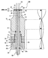
FIG. 1 is a cross-sectional view showing a schematic configuration of the ultrasonic spraying apparatus according to the first embodiment of the present invention. The ultrasonic spray device shown in the present embodiment is applied as a spray device that atomizes and sprays liquids such as water, fuel, and chemicals. As a more specific example, in the urea SCR system of a vehicle, Applied to urea water spray for purifying nitrogen oxides.
図1に示すように、超音波噴霧装置100は、要部として、筒状部材10と、筒状部材10の一端側(噴霧先端側)に固定された多孔板20と、多孔板20を超音波振動させるボルト締めランジュバン型振動子30と、筒状部材10の内部に配置された静止部材40と、を有している。
As shown in FIG. 1, the
筒状部材10は、その少なくとも一部が、ボルト締めランジュバン型振動子30で生じた超音波振動を、多孔板20に伝達する機能を果たす筒状の部材であり、その噴霧側端面(以下、先端面11と示す)には、複数の墳孔21が筒内部12の開口領域に臨むように、多孔板20が直接的に固定されている。また、筒内部12には、多孔板20に供給される液体50の流路51と、流路51の端部に連結された液体50の圧力室52が設けられている。
The
本実施形態では、筒状部材10が金属材料を用いて断面略円環状に形成されており、筒内部12の開口領域は、その断面積を一定としつつ振動方向に沿って直線的に延びている。また、筒状部材10は、後述する圧電振動子31,32の振動方向(換言すれば、図1に白抜き矢印で示す多孔板20の振動方向であり、以下単に振動方向と示す)において、先端面11から所定範囲が、先端面11に近いほど断面積の小さいホーン形状となっており、残りの部分の外周形状は、その外周直径が後述する圧電振動子31,32の外周直径と略等しい一定の形状となっている。より詳しくは、図1の紙面右側に示す振動モードのように、多孔板20の配置位置が超音波振動の腹の位置となっており、該腹の位置から1/4周期ずれた節の位置までの範囲が、ホーン形状となっている。このように、ホーン形状の筒状部材10を採用すると、その面積比に応じて、図1に示すように超音波振動(振幅)を増幅することができる。
In this embodiment, the
そして、上記した筒状部材10の先端面11には、直径数十μm程度の墳孔21を厚さ0.1〜1mm程度の金属板に複数形成してなる多孔板20が、ロウ付、溶接等により固定されている。なお、多孔板20の外周形状は、筒状部材10の外周形状と同じ略円形となっており、多孔板20の外周端は、筒状部材10の先端面11における外周端と略一致されている。
And on the
また、筒状部材10における先端面11の裏面13(以下、後端面13と示す)には、圧電振動子31、電源側(正側)電極板33、圧電振動子32、GND側(接地側)電極板34、金属ブロック35の順で積層配置されている。そして、これら31〜35が、ボルト締めにより筒状部材10に一体結合されて、ボルト締めランジュバン型振動子30が構成されている。なお、図1に示す振動モードのように、一対の圧電振動子31,32の間に配置された電源側電極板33が振動の節位置となり、この節から各1/4周期ずれた腹間の1/2周期の部分が、ボルト締めランジュバン型振動子30となっている。すなわち、本実施形態では、筒状部材10の一部(振動方向において後端面13から上記した一方の腹までの範囲)が、金属ブロック35とともに、一対の圧電振動子31,32をその振動方向上下から挟み込む金属部材の一方(換言すればボルト締めランジュバン型振動子30の一部)となっている。
In addition, a
より詳しくは、金属ブロック35も、筒状部材10同様に振動方向に沿って延びた筒状とされ、筒内部35aに流路51が設けられている。この筒内部35aは、ボルト締めランジュバン型振動子30が構成された状態(以下単に締結状態と示す)で、筒状部材10における筒内部12と一体的に連結されるように、振動方向に対して略垂直な開口領域の形状及び断面積が、筒内部12の開口領域と一致されている。また、金属ブロック35は、振動方向に対して略垂直な断面形状が略円環状となっており、締結状態でその外周端が筒状部材10の後端面13における外周端と略一致される(その外周直径が、圧電振動子31,32の外周直径と略等しい)挟持部35bと、該挟持部35bの一部から突出し、その先端から一部の範囲にボルトが構成された凸部35cを有している。
More specifically, the
一方、筒状部材10の後端面13における中央領域には、筒内部12の開口領域を取り囲むように所定深さの凹部14が設けられ、この凹部14の側壁に、上記したボルトと対をなすナットが構成されている。また、一対の圧電振動子31,32は、振動方向に対して略垂直な断面が、筒状部材10の後端面13において中央領域を取り囲む周辺領域と略一致する断面略円環状となっており、電源側電極板33及びGND側電極板34も、断面略円環状となっている。そして、GND側電極板34、圧電振動子32、電源側電極板33、及び圧電振動子31に対して金属ブロック35の凸部35cが挿通され、凸部35cの先端に構成されたボルトが、筒状部材10の後端面13に設けられた凹部14のナットと締結されて、ボルト締めランジュバン型振動子30が構成されている。
On the other hand, a
なお、電源側電極板33及びGND側電極板34は、その一部が、振動方向に対して略垂直な方向に引き出され、これにより駆動電圧が印加可能となっている。また、圧電振動子31,32は、金属ブロック35とは接しておらず、圧電振動子31は、振動方向における上下面が電源側電極板33及び金属ブロック35を介してGND側電極板34と電気的に接続された筒状部材10における後端面13の周辺領域と接しており、圧電振動子32は、振動方向における上下面が電源側電極板33及びGND側電極板34と接している。
Note that a part of the power supply
また、筒状部材10の筒内部12には、ボルト締めランジュバン型振動子30からの超音波振動の伝達が抑制され、且つ、液体50の流路51の少なくとも一部を構成しつつ多孔板20に相対するように、静止部材40が位置決め配置されている。そして、この静止部材40、多孔板20、及び筒内部12の壁面(筒状部材10の内周面)により、多孔板20の振動に応じて圧力が変化する圧力室52が構成されている。
In addition, the transmission of ultrasonic vibration from the bolted
本実施形態では、静止部材40が、金属材料を用いて振動方向に沿って延びる筒状となっており、筒状部材10の筒内部12及び金属ブロック35の筒内部35aに配置されている。また、静止部材40における振動方向に垂直な断面の外周は、筒状部材10における筒内部12の壁面及び金属ブロック35における筒内部35aの壁面に対応した円環状となっており、静止部材40は、ゴムなどの弾性部材60を介して、金属ブロック35における筒内部35aの壁面に固定されている。この弾性部材60が、特許請求の範囲に記載の緩衝部材に相当するものであり、この弾性部材60によって、ボルト締めランジュバン型振動子30から静止部材40への超音波振動の伝達が抑制されるようになっている。また、弾性部材60により、静止部材40が金属ブロック35、ひいては金属ブロック35と一体化された筒状部材10に対して位置決め固定されている。
In the present embodiment, the
また、筒状の静止部材40は、金属ブロック35の筒内部35aを貫通して一方の開口端が外部まで引き出されており、他方の開口端42(多孔板20側の開口端42)が、多孔板20における筒内部12の開口領域に臨む部位に対して所定距離離れた位置とされて、多孔板20と静止部材40とが相対する位置関係となっている。そして、静止部材40の内周面41により、超音波噴霧装置100における流路51が構成されており、静止部材40における開口端42、筒内部12の壁面における静止部材40と相対していない部位、及び多孔板20の内面22(静止部材40との対向面)により、圧力室52が構成されている。このように、圧力室52は流路51の一端と液体50を流通可能に連通されており、流路51よりも、振動方向に略垂直な方向における開口領域の断面積が大きくなっている。
また、静止部材40の開口端42が圧力室52の底面となっている。このような底面としての開口端42の位置は、多孔板20の超音波振動による圧力室52内の圧力上昇が容易で、且つ、圧力室52内への液体50の流入が容易な、圧力室52の厚みが0.5〜1mm程度となる位置とすると良い。
Further, the cylindrical
The
なお、図1に示す符号61は、圧力室52側から、筒状部材10における筒内部12の壁面と静止部材40の外周面との間の隙間を介して、圧電振動子31,32や電極板33,34へ、液体50がリークするのを防ぐOリング61である。また、符号15は、筒状部材10におけるホーン形状部位の後端(振動の節の位置)に設けられたフランジであり、このフランジ15を介して、超音波噴霧装置100が他部材に固定されるようになっている。
1 denotes the
次に、上記した超音波噴霧装置100における噴霧原理について説明する。ボルト締めランジュバン型振動子30を構成する電極板33,34に所定の駆動電圧を印加すると、圧電振動子31,32がその積層方向に振動する。このボルト締めランジュバン型振動子30の超音波振動は、筒状部材10を通じて伝達されるとともにホーン形状部位にて振動の振幅が拡大され、筒状部材10の先端面11に固定された多孔板20に伝達される。本実施形態では、多孔板20が振動の腹に位置するため、多孔板20(における筒内部12の開口領域に臨む部位)が、大きな振幅をもって図1に示す振動方向に超音波振動することとなる。
Next, the spray principle in the
一方、静止部材40は、上記したように、弾性部材60を介して金属ブロック35における筒内部35aの壁面に固定されているため、ボルト締めランジュバン型振動子30の超音波振動が殆ど伝わらず、常に静止状態となっている。この静止部材40の開口端42は、筒内部12の壁面における静止部材40と相対していない部位及び多孔板20の内面22とともに圧力室52を構成しており、超音波振動する多孔板20と静止された静止部材40とは、相対する位置関係となっている。したがって、流路51を通って圧力室52に流入した液体50には、ボルト締めランジュバン型振動子30(多孔板20)の超音波振動に伴って、超音波振動周期の圧力変化が生じる。
On the other hand, since the
この圧力変化は、振動方向において、多孔板20が静止部材40側に変位すると圧力が高くなり、逆に静止部材40から離れる方向に変位すると圧力が低くなって液体50のキャビテーションが発生する。このような圧力変化が、圧力室52から多孔板20の噴孔21を通って噴出する液体50に作用すると、圧力室52の圧力が高いときには噴出が加速され、逆に圧力が低くキャビテーションが発生するときには噴出が阻害されることとなる。このように、多孔板20の噴孔21を通って噴出する液体50は、超音波振動周期で噴出する噴霧53の形態となる。
This pressure change increases in the vibration direction when the
次に、本実施形態に係る超音波噴霧装置100の特徴的な効果について説明する。本実施形態に係る超音波噴霧装置100は、ボルト締めランジュバン型振動子30により多孔板20が超音波振動される装置構成となっており、筒状部材10の筒内部12であって相対する多孔板20と静止部材40との間に、流路51に連通されて圧力室52が設けてられている。したがって、振動方向に垂直な方向において、超音波噴霧装置100の体格を、従来よりも小型化することができる。また、筒状部材10の先端面11に多孔板20が直接的に固定され、この多孔板20を含めて、上記したように、筒状部材10の筒内部12に圧力室52が設けられている。したがって、従来よりも装置100の構成を簡素化することができる。以上から、本実施形態に係る超音波噴霧装置100は、構造が簡素で、圧電振動子31,32の振動方向に垂直な方向における体格の小型化に適した超音波噴霧装置となっている。
Next, a characteristic effect of the
また、本実施形態では、筒状部材10の先端面11に多孔板20が直接固定されており、ボルト締めランジュバン型振動子30の超音波振動が、筒状部材10を通じて多孔板20に伝達される。したがって、図示されないポンプにより圧送された液体50の圧力が低圧で、多孔板20の表面23(内面22の裏面側である外面23)に厚さ数十μm程度の液膜が生じたとしても、多孔板20自体の超音波振動によって、この液膜を霧化させて噴射させることができる。したがって、低圧での液体50のぼた落ちを抑制することができる。
In this embodiment, the
また、本実施形態では、静止部材40が、筒状部材10の内周形状に応じた外周形状を有する筒状とされ、ボルト締めランジュバン型振動子30からの超音波振動の伝達を抑制する弾性部材60を介して、筒状部材10の筒内部12に位置決め配置されている。そして、静止部材40の内周面41により、静止部材40の筒内に流路51が構成されている。したがって、弾性部材60と液体50とが接触しない構成となっており、静止部材40の内周面41はその形状が安定しているので、圧力室52へ液体50を安定供給することができる。
In the present embodiment, the
また、本実施形態では、筒状部材10の一部が、ボルト締めランジュバン型振動子30を構成する一対の金属部材の一方を兼ねている。したがって、装置100の構成をより簡素化することができる。そして、これにより、装置100の組み付け工数も削減することができる。
In the present embodiment, a part of the
以上、本発明の好ましい実施形態について説明したが、本発明は上述した実施形態になんら制限されることなく、本発明の主旨を逸脱しない範囲において、種々変形して実施することが可能である。 The preferred embodiments of the present invention have been described above. However, the present invention is not limited to the above-described embodiments, and various modifications can be made without departing from the spirit of the present invention.
本実施形態では、静止部材40が、金属ブロック35の筒内部35aを貫通する例を示した。しかしながら、静止部材40の形態としては、上記例に限定されるものではなく、ボルト締めランジュバン型振動子30からの超音波振動の伝達が抑制され、且つ、液体50の流路51の少なくとも一部を構成しつつ多孔板20に相対するように位置決め配置されていれば良い。例えば図2に示す例では、静止部材40の長さが図1に示した例よりも短く、静止部材40は筒状部材10におけるホーン形状部位の後端付近まで延設されており、筒状部材10のホーン形状部位の後端付近(超音波振動の節位置付近)で、弾性部材60を介して筒内部12の壁面に位置決め固定された構成となっている。なお、流路51は、静止部材40の内周面41だけでなく、筒状部材10における筒内部12の壁面によって構成されている。詳しくは、筒状部材10の筒内部12が、静止部材40が配置された後端から先端面11まで範囲の先端側部位12aと、静止部材40が配置された後端よりも後端側の後端側部位12bとを有し、先端側部位12aのほうが後端側部位12bよりも開口領域の断面積が大きくなっている。また、後端側部位12bと静止部材40の内周面41とで開口領域の断面積及び形状が一致されており、流路51が、静止部材40の内周面41及び筒内部12における後端側部位12bの壁面によって構成されている。また、筒状部材10は、後端面13の一部から突出し、一部にボルトが構成された凸部16を有しており、金属ブロック35には、多孔板20側の面の中央領域に、筒内部35aの開口領域を取り囲むように所定深さの凹部35dが設けられ、この凹部35dの側壁に、上記したボルトと対をなすナットが構成されている。そして、圧電振動子31、電源側電極板33、圧電振動子32、GND側電極板34、及び金属ブロック35に対して、筒状部材10の凸部16が挿通され、凸部16に構成されたボルトが、金属ブロック35に設けられた凹部35dのナットと締結されて、ボルト締めランジュバン型振動子30が構成されている。図2は、変形例の概略構成を示す断面図である。
In this embodiment, the example in which the
また、本実施形態では、静止部材40が筒状とされる例を示した。しかしながら、筒状でなく、静止部材40の外面が流路51とされるような形状を採用することもできる。
Further, in the present embodiment, an example in which the
本実施形態では、筒状部材10の内部と金属ブロック35の内部に、流路51が設けられる例を示した。しかしながら、例えば図3に示すように、筒状部材10の内部のみに流路51が設けられた構成としても良い。図3に示す例では、筒状部材10の内部のみに、筒状部材10の筒内部12(後端側部位12b)の壁面及び静止部材40の内周面41によって断面略L字状の流路51が構成されている。そして、筒状部材10の外周面における振動の節に近い部位で、流路51の一端が外部に露出されている。なお、図3に示す例では、静止部材40の構成が図2に示した構成と同じとなっており、金属ブロック35には振動方向に沿って延びる開口領域が設けられていない。図3は、変形例の概略構成を示す断面図である。
In this embodiment, the example in which the
本実施形態では、筒状部材10の一部が、ボルト締めランジュバン型振動子30の一部(一対の金属部材の一方)を兼ねる例を示した。しかしながら、例えば図4に示すように、筒状部材10とボルト締めランジュバン型振動子30とが独立した構成としてもよい。図4では、一対の金属部材として、金属ブロック35とともに、上記した圧電振動子31,32、各電極板33,34を挟み込む金属部材36を有している。なお、図4に示す例では、圧電振動子31,32、各電極板33,34、金属ブロック35の構成は、第1実施形態に示した構成(図1参照)と同じ構成となっている。金属部材36は振動方向に沿って延びる筒状となっており、振動方向に対し略垂直な断面が、略円環状となっている。また、締結状態でその外周端が筒状部材10の後端面13における外周端と略一致(その外周直径が、圧電振動子31,32の外周直径と略等しく)されており、その後端面における中央領域には、筒内部36aの開口領域を取り囲むように所定深さの凹部36bが設けられている。そして、この凹部36bの側壁に、金属ブロック35の凸部35cに構成されたボルトと対をなすナットが構成されている。また、図4に示すように、金属ブロック35と筒状部材10とが締結によって互いに一体化されている。図4は、変形例の概略構成を示す断面図である。
In the present embodiment, an example in which a part of the
本実施形態では、筒状部材10がホーン形状の部位を有する例を示した。しかしながら、ホーン形状部位を有さない構成としてもよい。
In this embodiment, the example which the
本実施形態では、圧力室52が、静止部材40の開口端42、筒状部材10の筒内部12における壁面、多孔板20の内面22によって構成される例を示した。しかしながら、圧力室52は、筒状部材10の筒内部12であって、相対する多孔板20と静止部材40を圧力室52の壁面とするものであれば良い。換言すれば、筒状部材10の筒内部12であって、相対する多孔板20と静止部材40との間に構成されたものであれば良い。したがって、圧力室52の側面は、筒状部材10の筒内部12における壁面に限定されるものではない。例えば、静止部材40の開口端42における周縁領域から突出され、筒内部12の壁面に隣接する環状の凸部の内周面を、圧力室52の側面としても良い。
In the present embodiment, an example in which the
10・・・筒状部材
11・・・先端面
12・・・筒内部
20・・・多孔板
30・・・ボルト締めランジュバン型振動子
31,32・・・圧電振動子
35・・・金属ブロック(金属部材)
40・・・静止部材
42・・・開口端
50・・・液体
51・・・流路
52・・・圧力室
100・・・超音波噴霧装置
DESCRIPTION OF
40 ...
Claims (4)
その振動方向に積層された一対の圧電振動子と、積層方向の上下から前記圧電振動子を挟み込む一対の金属部材とを有し、前記多孔板を超音波振動させるボルト締めランジュバン型振動子と、
前記ボルト締めランジュバン型振動子からの超音波振動の伝達が抑制され、前記筒状部材の筒内部に、前記流路の少なくとも一部を構成しつつ前記多孔板に相対するように位置決め配置された静止部材と、を備え、
前記筒状部材の筒内部には、前記流路の一端と連結され、前記多孔板の振動に応じて圧力が変化する圧力室が、相対する前記多孔板と前記静止部材との間に構成されていることを特徴とする超音波噴霧装置。 A cylindrical member in which a porous plate is fixed to an opening end so as to close an opening on one end side, and a liquid flow path is provided inside the cylinder;
A bolt-clamped Langevin type vibrator that has a pair of piezoelectric vibrators laminated in the vibration direction and a pair of metal members that sandwich the piezoelectric vibrator from above and below in the lamination direction, and ultrasonically vibrates the porous plate;
Transmission of ultrasonic vibration from the bolted Langevin type vibrator is suppressed, and positioning is arranged inside the cylinder of the cylindrical member so as to be opposed to the porous plate while forming at least a part of the flow path. A stationary member,
Inside the cylinder of the cylindrical member, a pressure chamber connected to one end of the flow path and changing pressure according to vibration of the porous plate is formed between the opposed porous plate and the stationary member. An ultrasonic spraying device characterized by comprising:
Priority Applications (1)
| Application Number | Priority Date | Filing Date | Title |
|---|---|---|---|
| JP2008111757A JP2009262012A (en) | 2008-04-22 | 2008-04-22 | Ultrasonic sprayer |
Applications Claiming Priority (1)
| Application Number | Priority Date | Filing Date | Title |
|---|---|---|---|
| JP2008111757A JP2009262012A (en) | 2008-04-22 | 2008-04-22 | Ultrasonic sprayer |
Publications (1)
| Publication Number | Publication Date |
|---|---|
| JP2009262012A true JP2009262012A (en) | 2009-11-12 |
Family
ID=41388544
Family Applications (1)
| Application Number | Title | Priority Date | Filing Date |
|---|---|---|---|
| JP2008111757A Withdrawn JP2009262012A (en) | 2008-04-22 | 2008-04-22 | Ultrasonic sprayer |
Country Status (1)
| Country | Link |
|---|---|
| JP (1) | JP2009262012A (en) |
Cited By (3)
| Publication number | Priority date | Publication date | Assignee | Title |
|---|---|---|---|---|
| CN109569390A (en) * | 2018-10-29 | 2019-04-05 | 彭志军 | A kind of ultrasonic wave oil fuel gasification installation |
| CN114178116A (en) * | 2021-12-16 | 2022-03-15 | 广州大学 | Ultrasonic atomization device for high-viscosity liquid |
| US20220314263A1 (en) * | 2018-01-30 | 2022-10-06 | Ford Motor Company | Reversible nozzle in ultrasonic atomizer for clog prevention |
-
2008
- 2008-04-22 JP JP2008111757A patent/JP2009262012A/en not_active Withdrawn
Cited By (3)
| Publication number | Priority date | Publication date | Assignee | Title |
|---|---|---|---|---|
| US20220314263A1 (en) * | 2018-01-30 | 2022-10-06 | Ford Motor Company | Reversible nozzle in ultrasonic atomizer for clog prevention |
| CN109569390A (en) * | 2018-10-29 | 2019-04-05 | 彭志军 | A kind of ultrasonic wave oil fuel gasification installation |
| CN114178116A (en) * | 2021-12-16 | 2022-03-15 | 广州大学 | Ultrasonic atomization device for high-viscosity liquid |
Similar Documents
| Publication | Publication Date | Title |
|---|---|---|
| US12409282B2 (en) | Vibration systems and methods | |
| JP5898729B2 (en) | Fully sealed piezoelectric atomization module with two air chambers | |
| JP4627766B2 (en) | Nebulizer | |
| US20080156320A1 (en) | Ultrasonic nebulizer and method for atomizing liquid | |
| CN102307674A (en) | Atomization component and atomizer with the atomization component | |
| JP6539468B2 (en) | Ultrasonic atomizer | |
| JPS59162972A (en) | atomizer | |
| JP4990707B2 (en) | Ultrasonic fog generator | |
| US20070051827A1 (en) | Spraying device | |
| JP5423813B2 (en) | Atomizer | |
| JP2006280910A (en) | Fine mist generator | |
| JP2009262012A (en) | Ultrasonic sprayer | |
| JP2003265994A5 (en) | ||
| JPH02145296A (en) | Nozzle for water jet | |
| KR20130008258A (en) | Ultrasonic spray nozzle | |
| US20130161407A1 (en) | Device and method for nebulising or atomising free-flowing media | |
| JP4812657B2 (en) | Ultrasonic atomizer and equipment equipped with the same | |
| JP3299830B2 (en) | Vibrating water jet injector and its vibration amplifier | |
| JP2009254949A (en) | Atomizing apparatus | |
| JP2008086898A (en) | Ultrasonic cleaning device | |
| JP5060594B2 (en) | Airless spray coating equipment | |
| JP2003326202A (en) | Liquid spray head and liquid spray apparatus using the same | |
| JP6832564B2 (en) | Focused sound field forming device | |
| JPH0373343B2 (en) | ||
| JP3129307U (en) | Micro droplet generator |
Legal Events
| Date | Code | Title | Description |
|---|---|---|---|
| A711 | Notification of change in applicant |
Free format text: JAPANESE INTERMEDIATE CODE: A711 Effective date: 20090910 |
|
| A521 | Request for written amendment filed |
Free format text: JAPANESE INTERMEDIATE CODE: A821 Effective date: 20090917 |
|
| RD02 | Notification of acceptance of power of attorney |
Free format text: JAPANESE INTERMEDIATE CODE: A7422 Effective date: 20090917 |
|
| A521 | Request for written amendment filed |
Free format text: JAPANESE INTERMEDIATE CODE: A821 Effective date: 20090910 |
|
| A300 | Application deemed to be withdrawn because no request for examination was validly filed |
Free format text: JAPANESE INTERMEDIATE CODE: A300 Effective date: 20110705 |