JP2009509111A - Method of adding fuel to exhaust gas and related automobile - Google Patents
Method of adding fuel to exhaust gas and related automobile Download PDFInfo
- Publication number
- JP2009509111A JP2009509111A JP2008531758A JP2008531758A JP2009509111A JP 2009509111 A JP2009509111 A JP 2009509111A JP 2008531758 A JP2008531758 A JP 2008531758A JP 2008531758 A JP2008531758 A JP 2008531758A JP 2009509111 A JP2009509111 A JP 2009509111A
- Authority
- JP
- Japan
- Prior art keywords
- engine
- transmission
- law
- fuel
- particulate filter
- Prior art date
- Legal status (The legal status is an assumption and is not a legal conclusion. Google has not performed a legal analysis and makes no representation as to the accuracy of the status listed.)
- Pending
Links
Images


Classifications
-
- F—MECHANICAL ENGINEERING; LIGHTING; HEATING; WEAPONS; BLASTING
- F02—COMBUSTION ENGINES; HOT-GAS OR COMBUSTION-PRODUCT ENGINE PLANTS
- F02D—CONTROLLING COMBUSTION ENGINES
- F02D41/00—Electrical control of supply of combustible mixture or its constituents
- F02D41/02—Circuit arrangements for generating control signals
- F02D41/021—Introducing corrections for particular conditions exterior to the engine
- F02D41/0235—Introducing corrections for particular conditions exterior to the engine in relation with the state of the exhaust gas treating apparatus
- F02D41/027—Introducing corrections for particular conditions exterior to the engine in relation with the state of the exhaust gas treating apparatus to purge or regenerate the exhaust gas treating apparatus
- F02D41/029—Introducing corrections for particular conditions exterior to the engine in relation with the state of the exhaust gas treating apparatus to purge or regenerate the exhaust gas treating apparatus the exhaust gas treating apparatus being a particulate filter
-
- F—MECHANICAL ENGINEERING; LIGHTING; HEATING; WEAPONS; BLASTING
- F02—COMBUSTION ENGINES; HOT-GAS OR COMBUSTION-PRODUCT ENGINE PLANTS
- F02D—CONTROLLING COMBUSTION ENGINES
- F02D41/00—Electrical control of supply of combustible mixture or its constituents
- F02D41/30—Controlling fuel injection
- F02D41/38—Controlling fuel injection of the high pressure type
- F02D41/40—Controlling fuel injection of the high pressure type with means for controlling injection timing or duration
- F02D41/402—Multiple injections
- F02D41/405—Multiple injections with post injections
-
- F—MECHANICAL ENGINEERING; LIGHTING; HEATING; WEAPONS; BLASTING
- F16—ENGINEERING ELEMENTS AND UNITS; GENERAL MEASURES FOR PRODUCING AND MAINTAINING EFFECTIVE FUNCTIONING OF MACHINES OR INSTALLATIONS; THERMAL INSULATION IN GENERAL
- F16H—GEARING
- F16H61/00—Control functions within control units of change-speed- or reversing-gearings for conveying rotary motion ; Control of exclusively fluid gearing, friction gearing, gearings with endless flexible members or other particular types of gearing
- F16H61/02—Control functions within control units of change-speed- or reversing-gearings for conveying rotary motion ; Control of exclusively fluid gearing, friction gearing, gearings with endless flexible members or other particular types of gearing characterised by the signals used
- F16H61/0202—Control functions within control units of change-speed- or reversing-gearings for conveying rotary motion ; Control of exclusively fluid gearing, friction gearing, gearings with endless flexible members or other particular types of gearing characterised by the signals used the signals being electric
- F16H61/0204—Control functions within control units of change-speed- or reversing-gearings for conveying rotary motion ; Control of exclusively fluid gearing, friction gearing, gearings with endless flexible members or other particular types of gearing characterised by the signals used the signals being electric for gearshift control, e.g. control functions for performing shifting or generation of shift signal
- F16H61/0213—Control functions within control units of change-speed- or reversing-gearings for conveying rotary motion ; Control of exclusively fluid gearing, friction gearing, gearings with endless flexible members or other particular types of gearing characterised by the signals used the signals being electric for gearshift control, e.g. control functions for performing shifting or generation of shift signal characterised by the method for generating shift signals
-
- B—PERFORMING OPERATIONS; TRANSPORTING
- B60—VEHICLES IN GENERAL
- B60Y—INDEXING SCHEME RELATING TO ASPECTS CROSS-CUTTING VEHICLE TECHNOLOGY
- B60Y2300/00—Purposes or special features of road vehicle drive control systems
- B60Y2300/47—Engine emissions
- B60Y2300/476—Regeneration of particle filters
-
- F—MECHANICAL ENGINEERING; LIGHTING; HEATING; WEAPONS; BLASTING
- F02—COMBUSTION ENGINES; HOT-GAS OR COMBUSTION-PRODUCT ENGINE PLANTS
- F02D—CONTROLLING COMBUSTION ENGINES
- F02D2250/00—Engine control related to specific problems or objectives
- F02D2250/11—Oil dilution, i.e. prevention thereof or special controls according thereto
-
- F—MECHANICAL ENGINEERING; LIGHTING; HEATING; WEAPONS; BLASTING
- F16—ENGINEERING ELEMENTS AND UNITS; GENERAL MEASURES FOR PRODUCING AND MAINTAINING EFFECTIVE FUNCTIONING OF MACHINES OR INSTALLATIONS; THERMAL INSULATION IN GENERAL
- F16H—GEARING
- F16H59/00—Control inputs to control units of change-speed- or reversing-gearings for conveying rotary motion
- F16H59/74—Inputs being a function of engine parameters
- F16H2059/743—Inputs being a function of engine parameters using engine performance or power for control of gearing
-
- F—MECHANICAL ENGINEERING; LIGHTING; HEATING; WEAPONS; BLASTING
- F16—ENGINEERING ELEMENTS AND UNITS; GENERAL MEASURES FOR PRODUCING AND MAINTAINING EFFECTIVE FUNCTIONING OF MACHINES OR INSTALLATIONS; THERMAL INSULATION IN GENERAL
- F16H—GEARING
- F16H61/00—Control functions within control units of change-speed- or reversing-gearings for conveying rotary motion ; Control of exclusively fluid gearing, friction gearing, gearings with endless flexible members or other particular types of gearing
- F16H2061/0018—Transmission control for optimising exhaust emissions
-
- F—MECHANICAL ENGINEERING; LIGHTING; HEATING; WEAPONS; BLASTING
- F16—ENGINEERING ELEMENTS AND UNITS; GENERAL MEASURES FOR PRODUCING AND MAINTAINING EFFECTIVE FUNCTIONING OF MACHINES OR INSTALLATIONS; THERMAL INSULATION IN GENERAL
- F16H—GEARING
- F16H61/00—Control functions within control units of change-speed- or reversing-gearings for conveying rotary motion ; Control of exclusively fluid gearing, friction gearing, gearings with endless flexible members or other particular types of gearing
- F16H61/02—Control functions within control units of change-speed- or reversing-gearings for conveying rotary motion ; Control of exclusively fluid gearing, friction gearing, gearings with endless flexible members or other particular types of gearing characterised by the signals used
- F16H61/0202—Control functions within control units of change-speed- or reversing-gearings for conveying rotary motion ; Control of exclusively fluid gearing, friction gearing, gearings with endless flexible members or other particular types of gearing characterised by the signals used the signals being electric
- F16H61/0204—Control functions within control units of change-speed- or reversing-gearings for conveying rotary motion ; Control of exclusively fluid gearing, friction gearing, gearings with endless flexible members or other particular types of gearing characterised by the signals used the signals being electric for gearshift control, e.g. control functions for performing shifting or generation of shift signal
- F16H61/0213—Control functions within control units of change-speed- or reversing-gearings for conveying rotary motion ; Control of exclusively fluid gearing, friction gearing, gearings with endless flexible members or other particular types of gearing characterised by the signals used the signals being electric for gearshift control, e.g. control functions for performing shifting or generation of shift signal characterised by the method for generating shift signals
- F16H2061/0232—Selecting ratios for bringing engine into a particular state, e.g. for fast warming up or for reducing exhaust emissions
-
- Y—GENERAL TAGGING OF NEW TECHNOLOGICAL DEVELOPMENTS; GENERAL TAGGING OF CROSS-SECTIONAL TECHNOLOGIES SPANNING OVER SEVERAL SECTIONS OF THE IPC; TECHNICAL SUBJECTS COVERED BY FORMER USPC CROSS-REFERENCE ART COLLECTIONS [XRACs] AND DIGESTS
- Y02—TECHNOLOGIES OR APPLICATIONS FOR MITIGATION OR ADAPTATION AGAINST CLIMATE CHANGE
- Y02T—CLIMATE CHANGE MITIGATION TECHNOLOGIES RELATED TO TRANSPORTATION
- Y02T10/00—Road transport of goods or passengers
- Y02T10/10—Internal combustion engine [ICE] based vehicles
- Y02T10/40—Engine management systems
Landscapes
- Engineering & Computer Science (AREA)
- General Engineering & Computer Science (AREA)
- Mechanical Engineering (AREA)
- Chemical & Material Sciences (AREA)
- Combustion & Propulsion (AREA)
- Electrical Control Of Air Or Fuel Supplied To Internal-Combustion Engine (AREA)
- Control Of Driving Devices And Active Controlling Of Vehicle (AREA)
- Control Of Vehicle Engines Or Engines For Specific Uses (AREA)
- Control Of Transmission Device (AREA)
- Sampling And Sample Adjustment (AREA)
Abstract
本発明は、ロボット化された自動変速装置(16)又は無段トルク変動式の自動変速装置(16)を備える自動車(V)のディーゼルエンジン燃焼室(12)内へ、後期及び/又は遅延燃料注入を行うことにより、排気ガスに燃料を添加する方法に関する。本発明は、変速装置(16)の減速比を規定する法則を変更し、燃焼室内に存在するオイル中の燃料の希釈を制限することを特徴とする。 The invention relates to late and / or delayed fuel into a diesel engine combustion chamber (12) of a motor vehicle (V) equipped with a robotized automatic transmission (16) or a continuously variable torque-variable automatic transmission (16). The present invention relates to a method of adding fuel to exhaust gas by performing injection. The present invention is characterized in that the law defining the reduction ratio of the transmission (16) is changed to limit the dilution of the fuel in the oil existing in the combustion chamber.
Description
本発明は、ディーゼルエンジンにおいて排気ガスに燃料を添加する方法に関する。
具体的には、本発明は、自動式変速装置、ロボット式変速装置、又は無段変速装置(CVT)を備えるディーゼルエンジンを有する自動車に関する。
The present invention relates to a method of adding fuel to exhaust gas in a diesel engine.
Specifically, the present invention relates to an automobile having a diesel engine equipped with an automatic transmission, a robotic transmission, or a continuously variable transmission (CVT).
このような、排気ガスに燃料を添加する方法は、特に、排気ライン上に微粒子フィルタ及び酸化触媒を有する自動車において、微粒子フィルタ再生段階の間に実施可能である。
新しい汚染制御規準を遵守するために、エンジン燃焼室の下流に位置する排気ライン内に設置された微粒子フィルタを使う方法が知られている。この微粒子フィルタは汚染微粒子を保持し、ディーゼルエンジンの運転と共に汚染微粒子が内部に蓄積される。
Such a method of adding fuel to the exhaust gas can be implemented during the particulate filter regeneration stage, particularly in an automobile having a particulate filter and an oxidation catalyst on the exhaust line.
In order to comply with the new pollution control standards, it is known to use a particulate filter installed in the exhaust line located downstream of the engine combustion chamber. The particulate filter retains contaminating particulates, and the particulate contaminants accumulate inside as the diesel engine operates.
微粒子フィルタ内における微粒子の蓄積は微粒子フィルタの詰まりを生じさせ、この詰まりがエンジンからの排気ガスの除去を大きく妨げる。これにより、排気ライン内に高い逆圧が生じ、エンジン性能に影響を与える。
微粒子フィルタに蓄積された微粒子を除去するためには、再生段階と呼ばれる段階の間に微粒子フィルタ内に存在する微粒子を定期的に焼却する方法が知られている。この目的のために、排気ガスの温度を上昇させることにより、微粒子の温度を上昇させ、その燃焼を開始させる。
Accumulation of particulates in the particulate filter can cause clogging of the particulate filter, which greatly impedes the removal of exhaust gas from the engine. This creates a high back pressure in the exhaust line and affects engine performance.
In order to remove the particulates accumulated in the particulate filter, a method is known in which particulates present in the particulate filter are periodically incinerated during a stage called a regeneration stage. For this purpose, by raising the temperature of the exhaust gas, the temperature of the particulates is raised and its combustion is started.
排気ガスの温度を上昇させる既知の一解決法では、微粒子フィルタ再生段階の間に特定の注入方法を採用する。第1の注入が、従来の方法により燃焼室内で、即ち燃焼室内でのピストン運動の圧縮行程の間に行なわれ、続いて遅延注入と呼ばれる1以上の追加注入が行われる。本発明において、遅延注入とは、エンジンのクランクシャフトが、ピストンの上死点に対応する自己位置を30〜40度の角度だけ通過したときの、爆発行程の間の燃焼室への燃料注入を意味する。
更なる解決法又は代替の解決法では、後期注入と呼ばれる1以上の注入を行う。本発明において、後期注入とは、クランクシャフトがピストンの上死点に対応する自己位置を100〜130度の角度だけ通過したときの、爆発行程の間の燃焼室への燃料注入を意味する。
One known solution for raising the temperature of the exhaust gas employs a specific injection method during the particulate filter regeneration phase. The first injection is performed in a conventional manner in the combustion chamber, i.e. during the compression stroke of the piston motion in the combustion chamber, followed by one or more additional injections called delayed injection. In the present invention, delayed injection refers to fuel injection into the combustion chamber during the explosion stroke when the crankshaft of the engine passes through a self-position corresponding to the top dead center of the piston by an angle of 30 to 40 degrees. means.
In a further or alternative solution, one or more injections called late injections are performed. In the present invention, late injection means fuel injection into the combustion chamber during the explosion stroke when the crankshaft passes through a self-position corresponding to the top dead center of the piston by an angle of 100 to 130 degrees.
このような後期燃料注入又は遅延燃料注入により、エンジンの排気ガスに燃料を添加することが可能である。これは、遅延注入の間に注入された燃料のように、後期注入の間に注入された燃料は燃焼室で完全に焼却されないためである。燃料の一部は、残留炭水化物及び一酸化炭素を酸化するために常套的に設けられる排気ラインの触媒部分に到達する。燃料はそこで酸化され、それにより酸化触媒内及びその下流のガスの温度を上昇させる。こうして加熱されたガスは、微粒子フィルタの再生に使用することができる。
これにより、1以上の遅延燃料注入及び/又は後期燃料注入を含む方法は、例えば微粒子フィルタを再生するために、ディーゼルエンジンの排気ガスに燃料を添加するのに役立つ。更に一般的には、これらの方法は、内燃機関から出る排気ガス中の燃料濃度を増大させるのに役立つ。
By such late fuel injection or delayed fuel injection, it is possible to add fuel to the exhaust gas of the engine. This is because the fuel injected during the late injection, like the fuel injected during the delayed injection, is not completely incinerated in the combustion chamber. A portion of the fuel reaches the catalyst portion of the exhaust line that is conventionally provided to oxidize residual carbohydrates and carbon monoxide. The fuel is oxidized there, thereby raising the temperature of the gas in and downstream of the oxidation catalyst. The gas thus heated can be used for regeneration of the particulate filter.
Thus, methods that include one or more delayed fuel injections and / or late fuel injections are useful for adding fuel to diesel engine exhaust gas, for example, to regenerate a particulate filter. More generally, these methods serve to increase the fuel concentration in the exhaust gas exiting the internal combustion engine.
しかし、注入が爆発行程の間に行なわれるので、注入された燃料の一部は実際上、ピストンとシリンダヘッドと共に燃焼室の境界を画定するシリンダ・ライナ上に直接に噴霧される。この燃料はその後、前記ライナを覆うオイルに希釈される。このような希釈は少なくとも2つの問題を起こす。一つは、この潤滑油がシリンダ・ライナに沿ってエンジンの下部クランクケースへ流れることである。このようにして、希釈された燃料が下部クランクケース内の潤滑油を汚染し、これによりオイルの潤滑特性が低減し、場合によってはエンジンに重大な問題が生じ、エンジンの寿命が顕著に短縮する。もう一つの問題は、オイルで希釈されたこの燃料が排気ガスと共に排出されず、それにより酸化触媒中で焼却されるべきこの燃料の量が減少することである。 However, because the injection takes place during the explosion stroke, some of the injected fuel is actually sprayed directly onto the cylinder liner that defines the combustion chamber boundary with the piston and cylinder head. This fuel is then diluted in oil that covers the liner. Such dilution causes at least two problems. One is that this lubricating oil flows along the cylinder liner to the lower crankcase of the engine. In this way, the diluted fuel contaminates the lubricating oil in the lower crankcase, thereby reducing the oil's lubrication characteristics and, in some cases, causing serious problems with the engine and significantly shortening the life of the engine. . Another problem is that this fuel diluted with oil is not discharged with the exhaust gas, thereby reducing the amount of this fuel to be incinerated in the oxidation catalyst.
本発明の目的は、排気ガスに燃料を添加すると同時に、燃焼室内のオイル中の燃料の希釈を減少させる方法を提供することである。 It is an object of the present invention to provide a method for reducing the dilution of fuel in oil in the combustion chamber while simultaneously adding fuel to the exhaust gas.
上記本発明の目的は、自動式、ロボット式、又は無段変速式の変速装置を備える自動車の、ディーゼルエンジンの燃焼室内への後期燃料注入及び/又は遅延燃料注入によって、排気ガスに燃料を添加する方法であって、前記変速装置の減速比を規定する法則を変更し、燃焼室内に存在するオイル中の燃料の希釈を制限することを特徴とする方法によって達成される。
本明細書の後述に詳細に示すように、変速装置の減速比を調整することによって、後期燃料注入及び/又は遅延燃料注入の間に注入された燃料の希釈が限界となる動作領域内でエンジンが動作することを防止できる。
The object of the present invention is to add fuel to exhaust gas by late fuel injection and / or delayed fuel injection into the combustion chamber of a diesel engine of an automobile equipped with an automatic, robotic or continuously variable transmission. This method is achieved by changing the law defining the reduction ratio of the transmission to limit the dilution of the fuel in the oil existing in the combustion chamber.
As will be described in detail later in this specification, the engine within the operating region where dilution of fuel injected during late fuel injection and / or delayed fuel injection is limited by adjusting the reduction ratio of the transmission. Can be prevented from operating.
本発明の第1の代替態様によれば、エンジンが、オイル中の燃料の希釈が限界となる動作領域内で動作する場合のみ、変速装置の減速比を規定する法則を変更する。
したがって、有利には、必要な場合にのみ減速比を変更し、残りの時間の間は変速装置の減速比を規定する法則は変更しない。こうしてこの動作は、運転者には実際上感知されない。しかしながら、エンジンの動作点を決定するために追加センサが必要である。
According to a first alternative aspect of the invention, the law defining the reduction ratio of the transmission is changed only when the engine operates in an operating region where the dilution of fuel in oil is limited.
Thus, advantageously, the reduction ratio is changed only when necessary, and the law defining the reduction ratio of the transmission is not changed for the remaining time. Thus, this movement is practically not perceived by the driver. However, additional sensors are required to determine the engine operating point.
本発明の第2の代替態様によれば、エンジンが後期燃料注入及び/又は遅延燃料注入モードで動作すると直ちに、前記変速装置の減速比を規定する法則を変更する。
したがって、追加センサを添加する必要がない。故に、この方法は追加コストなしに実施可能である。
According to a second alternative aspect of the invention, as soon as the engine operates in the late fuel injection and / or delayed fuel injection mode, the law defining the reduction ratio of the transmission is changed.
Therefore, there is no need to add an additional sensor. Thus, this method can be implemented without additional cost.
好ましくは、エンジンがエンジン速度しきい値よりも低いエンジン速度で動作する場合にのみ、前記変速装置の減速比を規定する法則を変更し、変速装置の減速比を低下させる。
したがって、有利には、エンジン速度を増大させることによって、エンジン動作点を希釈領域の境界に近づけるか又は場合によっては希釈領域外に移動させることが提案される。
Preferably, only when the engine operates at an engine speed lower than an engine speed threshold, the law defining the reduction ratio of the transmission is changed to reduce the reduction ratio of the transmission.
Therefore, it is advantageously proposed to increase the engine speed to move the engine operating point closer to the boundary of the dilution region or possibly out of the dilution region.
好ましくは、エンジンがエンジン負荷しきい値よりも低いエンジン負荷で動作する場合にのみ、変速装置の減速比を規定する法則を変更し、変速装置の減速比を増大させる。
したがって、有利には、エンジン負荷を増大させることによって、エンジン動作点を希釈領域の境界に近づけるか又は場合によっては希釈領域外に移動させることが提案される。
Preferably, only when the engine operates at an engine load lower than the engine load threshold, the law defining the reduction ratio of the transmission is changed to increase the reduction ratio of the transmission.
Thus, it is advantageously proposed to increase the engine load to move the engine operating point closer to the boundary of the dilution region or possibly out of the dilution region.
好ましくは、自動式又はロボット式の変速装置の場合、公称ギヤシフト移行法則とは異なる少なくとも1つの変更ギヤシフト移行法則に従って変速装置を制御する。
したがって、有利には、変速装置の減速比の変化を制御することにより、エンジンが限界希釈動作領域内で動作することを防止することができる。この解決法は実施が容易である。
Preferably, in the case of an automatic or robotic transmission, the transmission is controlled according to at least one modified gear shift transition law different from the nominal gear shift transition law.
Therefore, advantageously, the engine can be prevented from operating in the limiting dilution operation region by controlling the change in the reduction ratio of the transmission. This solution is easy to implement.
好ましくは、公称ギヤシフト移行法則が第1ギヤに連関するエンジンの動作条件において、変更ギヤシフト移行法則は第1ギヤより高い第2ギヤに連関する。
したがって、有利には、エンジン負荷を高めてエンジンを動作させることが可能で、これにより、後述に示すように、エンジン動作点がオイル中の燃料の限界希釈領域から離れる方向に移動する。
Preferably, in engine operating conditions where the nominal gear shift transition law is associated with the first gear, the modified gear shift transition law is associated with a second gear that is higher than the first gear.
Therefore, advantageously, the engine can be operated with an increased engine load, thereby moving the engine operating point away from the critical dilution region of the fuel in the oil, as will be described later.
好ましくは、公称ギヤシフト移行法則及び変更ギヤシフト移行法則は、加速ペダル角及び車両速度の関数であり、変更ギヤシフト移行法則は、自動車速度の一の範囲内で、第1の加速ペダル角で一定となり、当該車両速度の範囲内で、公称ギヤシフト移行法則が、第1の加速ペダル角よりも小さい第2の加速ペダル角で一定となる。
したがって、有利には、ギヤシフト移行法則は、単に、エンジンを高い負荷で動作させるために変更される。
Preferably, the nominal gear shift transition law and the modified gear shift transition law are functions of the accelerator pedal angle and the vehicle speed, and the modified gear shift transition law is constant at the first accelerator pedal angle within a range of vehicle speeds; Within the range of the vehicle speed, the nominal gear shift transition law is constant at a second accelerator pedal angle that is smaller than the first accelerator pedal angle.
Thus, advantageously, the gear shift transition law is simply modified to operate the engine at high loads.
本発明はまた、自動車の排気ラインに取り付けられた微粒子フィルタを再生する方法にも関し、本発明の自動車は、前記微粒子フィルタの上流に取り付けられるか又はこの微粒子フィルタ内に組み込まれた酸化触媒を備え、ディーゼルエンジン式であり、自動式、ロボット式、又は無段変速式の変速装置を有している。本方法は、前記微粒子フィルタに蓄積した煤が、少なくとも部分的に前記酸化触媒中で生じる、上記全ての代替態様において開示された方法によって取得された排気ガスによって搬送される燃料の燃焼によって生じる熱を用いて焼却されることを特徴とする。 The present invention also relates to a method for regenerating a particulate filter mounted in an automobile exhaust line, the vehicle of the present invention having an oxidation catalyst mounted upstream of or incorporated in the particulate filter. It is a diesel engine type, and has an automatic type, robot type or continuously variable transmission type transmission. The method includes heat generated by combustion of fuel carried by exhaust gas obtained by the methods disclosed in all the alternative embodiments, wherein soot accumulated in the particulate filter is at least partially generated in the oxidation catalyst. It is characterized by being incinerated using.
本発明はまた、自動式、ロボット式、又は無段変速式の変速装置を有するディーゼルエンジン式の自動車に関し、本自動車は、上記全ての代替態様において開示された、排気ガスに燃料を添加する方法を実施するのに適した変速装置制御のための電子ユニットを備えることを特徴とする。 The present invention also relates to a diesel engine type vehicle having an automatic, robotic or continuously variable transmission, the method of adding fuel to exhaust gas as disclosed in all the above alternative embodiments. An electronic unit for transmission control suitable for carrying out is provided.
最後に、本発明は、更に、微粒子フィルタが、微粒子フィルタの上流に取り付けられるか又はこの微粒子フィルタ内に組み込まれる酸化触媒に結合されて取り付けられた排気ラインを備えた上記のような自動車にも関し、本自動車は、前記微粒子フィルタに蓄積した煤が、少なくとも部分的に前記酸化触媒中で生じる、前記排気ガスによって搬送される燃料の燃焼によって生じる熱を用いて焼却されることを特徴とする。 Finally, the invention further relates to a motor vehicle as described above with an exhaust line in which the particulate filter is mounted upstream of the particulate filter or coupled to an oxidation catalyst incorporated into the particulate filter. In the present invention, the soot accumulated in the particulate filter is incinerated using heat generated by combustion of fuel conveyed by the exhaust gas, which is generated at least partially in the oxidation catalyst. .
本発明の他の利点及び特徴は、添付図面を参照する例示的且つ非限定的実施例としてのみ提示する、後述の説明から明らかにする。 Other advantages and features of the present invention will become apparent from the following description, which is presented only as an illustrative and non-limiting example with reference to the accompanying drawings.
所与の速度nにおけるエンジンの負荷Chは、以下の式(E1)及び(E2)によって同じように定義される。

− Pe(n)は、所与の速度nにおけるエンジン出力であり、
− Pemax(n)は、同じ所与の速度nにおける最大エンジン出力であり、
− C(n)は、所与の速度nにおけるエンジントルクであり、
− Cmax(n)は、同じ所与の速度nにおける最大エンジントルクである。
更に、本明細書の残りの部分において、変速装置減速比と変速装置歯車比とを区別する。
The engine load Ch at a given speed n is defined similarly by the following equations (E1) and (E2).
-Pe (n) is the engine power at a given speed n;
Pe max (n) is the maximum engine power at the same given speed n,
C (n) is the engine torque at a given speed n;
C max (n) is the maximum engine torque at the same given speed n.
Further, in the remainder of the specification, a transmission reduction ratio and a transmission gear ratio are distinguished.
減速比ηreduction は、次式により既知の方法で定義される。
歯車比は係合速度を表わし、したがって自動式及びロボット式の変速装置にのみ関する。自動式又はロボット式の変速装置の各歯車比は、変速装置の減速比に対応する。
The reduction ratio η reduction is defined by a known method by the following equation.
The gear ratio represents the engagement speed and is therefore only relevant for automatic and robotic transmissions. Each gear ratio of the automatic or robot type transmission corresponds to the reduction ratio of the transmission.
更に、本説明の残りの部分においては、「公称」と呼ばれるギヤシフト移行法則、即ち後期注入又は遅延注入を行わない「通常」の注入段階で実施されるギヤシフト移行法則と、変更注入段階の全部又は一部の間に実施される変更ギヤシフト移行法則、即ち少なくとも1の遅延注入及び/又は少なくとも1の後期注入を含むギヤシフト移行法則とを区別する。
現時点では、実験室における分析のみが、エンジンの潤滑油中で希釈された燃料の割合を測定するのに役立つ。これらの分析は、エンジン負荷及びエンジン速度の関数としてエンジン燃料によるオイル希釈の割合をマッピングするのに役立つ。このようなマッピングの一例を図1に示す。
Furthermore, in the remainder of this description, the gear shift transition law called “nominal”, ie the gear shift transition law implemented in the “normal” injection phase without late injection or delayed injection, and all or A distinction is made between the modified gear shift transition law implemented during a part, ie the gear shift transition law comprising at least one delayed injection and / or at least one late injection.
At present, only laboratory analysis serves to determine the fraction of fuel diluted in engine lubricants. These analyzes help to map the rate of oil dilution by engine fuel as a function of engine load and engine speed. An example of such a mapping is shown in FIG.
図1において、斜線領域はディーゼルエンジンの一動作領域に対応し、この領域では、遅延注入方法及び/又は後期注入方法によって燃焼室内に注入された燃料の一部が、シリンダ・ライナを覆うエンジンの潤滑油中で希釈される。図1及び作成したがここでは図示しない他のマッピングにより、特に中程度の速度における、低負荷エンジン動作点で、潤滑油の希釈が高い傾向があること、エンジン速度が一定の場合に負荷が増大すると燃料によるオイルの希釈が減少することが判明した。
明らかに、この希釈領域の境界が近づくにつれてオイルによる燃料の希釈が減少する。
In FIG. 1, the shaded region corresponds to one operating region of a diesel engine, in which a portion of the fuel injected into the combustion chamber by the delayed injection method and / or the late injection method of the engine covers the cylinder liner. Diluted in lubricating oil. Figure 1 and other mappings that were created but not shown here indicate that the dilution of the lubricant tends to be high, especially at moderate speeds, at low load engine operating points, and the load increases when the engine speed is constant It turned out that the dilution of oil with fuel decreased.
Obviously, the dilution of the fuel with oil decreases as the boundary of this dilution region approaches.
本発明により、変速装置の歯車比を変更することにより、限界希釈領域内でエンジンが動作するのを防止することが提案される。
第1の解決法によれば、このような変速装置の減速比の変更は、変速装置の減速比を減少させるような変更である。こうして、ほぼ同じ車速を維持することによって、エンジン速度が増大する。図1において、例えば、始点を負荷Cheとエンジン速度neとに対応する点Peとすると、このような変速装置の減速比の変更は、オイル中の燃料希釈が低いエンジン動作領域に向かって動作点Peを矢印F1の方向に移動させる。
According to the invention, it is proposed to prevent the engine from operating in the limiting dilution region by changing the gear ratio of the transmission.
According to the first solution, such a change in the reduction ratio of the transmission is a change that reduces the reduction ratio of the transmission. Thus, by maintaining substantially the same vehicle speed, the engine speed is increased. In Figure 1, for example, when Pe point corresponding to the start point to the load Ch e and the engine speed n e, change of the reduction ratio of such transmissions, fuel dilution in oil toward the low engine operating region moving the operating point Pe in the direction of the arrow F 1.
例えば、自動モードにある自動式又はロボット式の変速装置について、ギヤシフト移行法則を変更することができる。このような変更では、公称ギヤシフト移行法則による第1のギヤに対応する所与の速度において、変更ギヤシフト移行法則が、低い減速比に対応する低いギヤ、好ましくはそれよりも一段低いギヤに連関する構成とすることができる。実際、エンジン速度はこれにより増大し、したがってエンジン動作点が、速度が大きく且つ負荷が小さいエンジン動作領域に向かって移動し、そこでオイル中の燃料の希釈が低減する。
このような変更は、1500〜3500rpmの速度範囲に対応する車速に対して特に適切である。その理由は、希釈領域の境界線がこの範囲内で下降するからである。
For example, the gear shift transition law can be changed for an automatic or robotic transmission in automatic mode. In such a change, at a given speed corresponding to the first gear according to the nominal gearshift transition law, the modified gearshift transition law is associated with a lower gear corresponding to a lower reduction ratio, preferably one gear lower than that. It can be configured. In fact, this increases the engine speed, so that the engine operating point moves towards an engine operating area where the speed is high and the load is low, where the dilution of fuel in oil is reduced.
Such a change is particularly appropriate for vehicle speeds corresponding to a speed range of 1500-3500 rpm. The reason is that the boundary line of the dilution region falls within this range.
別の解決法によれば、これと反対に、変速装置減速比を増大させることが提案される。
実際、車速がvaで歯車比raを有し、歯車比raと車速vaとに対応するエンジン速度がnaの自動車の場合、エンジンはトルクC(na)を出す。
According to another solution, on the contrary, it is proposed to increase the transmission reduction ratio.
In fact, having a gear ratio r a vehicle speed is v a, when the engine speed corresponding to the gear ratio r a and the vehicle speed v a is the vehicle n a, engine issues a torque C (n a).
次に、車速が同じvaであるが歯車比がraの次に高いrbである同じ自動車の場合、エンジン速度が変化して、naよりも低いnbに等しくなる。すると、これらの条件下では、エンジンはトルクC(nb)を出す。
この場合、負荷Ch(nb)が負荷Ch(na)よりも高いことが知られている。
Next, for the same car with the same v a but the same gear ratio r b after r a , the engine speed changes to be equal to n b lower than n a . Then, under these conditions, the engine produces torque C (n b ).
In this case, it is known that the load Ch (n b ) is higher than the load Ch (n a ).
したがって、エンジン負荷は、変速装置減速比を増大させることによって、即ち自動式又はロボット式の変速装置の場合には車速を一定に保ちながら高いギヤに係合させることによって、増大される。図1において、点Peを始点と考えると、変速装置の減速比のこのような変更は、エンジン動作点を矢印F2の方向に、負荷が高く速度が低いエンジン動作領域に移動させる。このようなエンジン動作領域においては、オイル中の燃料の希釈度の危険性は少ない。
特に、自動化モードの自動式又はロボット式の変速装置においては、エンジンが極度に低い負荷で動作するのを防止するためにギヤシフト移行法則を変更することが可能であり、特に、エンジンが極度に低い負荷で動作する場合に、当初に用いられたギヤよりも高いギヤ、好ましくは当初に用いられたギヤより一段高いギヤと係合するようなギヤシフトを行うようにギヤシフト移行法則を変更することができる。
Therefore, the engine load is increased by increasing the transmission reduction ratio, that is, in the case of an automatic or robotic transmission, by engaging a higher gear while keeping the vehicle speed constant. In Figure 1, considering the point Pe to start, such change of the reduction ratio of the transmission, in the direction of the engine operating point arrow F 2, the load is high speed is moved to the low engine operating region. In such an engine operating region, there is little risk of dilution of fuel in oil.
Especially in automatic or robotic transmissions in automation mode, it is possible to change the gear shift transition law to prevent the engine from operating at extremely low loads, especially the engine is extremely low When operating with a load, the gear shift transition law can be changed to perform a gear shift that engages a gear that is higher than the gear originally used, preferably one gear higher than the gear originally used. .
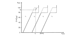
図2は、4つのギヤr1、r2、r3、及びr4を有する自動変速装置において、低負荷でのエンジンの動作を制限する目的を達成するギヤシフト移行法則の変更を概略的に示す。本発明において、「ギヤシフト移行法則」とは、正確には、加速ペダル角αpedal及び車速vvehicleの関数として隣接するギヤへのギヤシフトを規定する法則を意味する。
この図2において、加速ペダル角αpedalは、ペダルの近接地点に対応する加速ペダル角α0 pedalの割合(%)として示され、他方車速はkm/hで示される。
FIG. 2 schematically shows a change in the gear shift transition law that achieves the objective of limiting engine operation at low loads in an automatic transmission having four gears r 1 , r 2 , r 3 , and r 4. . In the present invention, the “gear shift transition law” means a law that defines a gear shift to an adjacent gear as a function of the accelerator pedal angle α pedal and the vehicle speed v vehicle .
In FIG. 2, the acceleration pedal angle α pedal is shown as a ratio (%) of the acceleration pedal angle α 0 pedal corresponding to the proximity point of the pedal , and the vehicle speed is shown in km / h.
この図2において、実線は種々の公称ギヤシフト移行法則を表わし、点線は本発明による変更ギヤシフト移行法則を表わす。
図2に示すように、本実施例における公称ギヤシフト移行法則は、0〜80%のペダル角に対する第1の直線部分を示し、次いで加速ペダル角α0 pedalの80%に等しい加速ペダル角の値で水平な平坦域を示す法則である。このギヤシフト移行法則は、加速ペダル角α0 pedalの80%より高い加速ペダル角に対応する図2の垂直部分で終結する。このような加速ペダルの踏み込みは、例えば、運転者が、エンジン速度を増大させるシフト・ダウンを命令することを可能にするために、又は速度コントローラ又はクルーズ・コントロールの動作停止を命令することを可能にするために、許容される。
In FIG. 2, the solid line represents various nominal gear shift transition laws, and the dotted line represents the modified gear shift transition law according to the present invention.
As shown in FIG. 2, the nominal gear shift transition law in this example shows a first straight line portion for a pedal angle of 0 to 80% and then a value of the accelerator pedal angle equal to 80% of the accelerator pedal angle α 0 pedal. This is a law indicating a horizontal flat area. This gear shift transition law ends at the vertical portion of FIG. 2 corresponding to an accelerator pedal angle higher than 80% of the accelerator pedal angle α 0 pedal . Such depression of the accelerator pedal can, for example, allow the driver to command a shift down to increase engine speed or to command the speed controller or cruise control to stop operating. To be acceptable.
図2に示すように、後期燃料注入及び/又は遅延燃料注入段階の間に変更された法則は、公称ギヤシフト移行法則の直線部分とほぼ同一の第1の部分を示すが、変更ギヤシフト移行法則では、平坦域が、加速ペダル角α0 pedalの、80%に等しい加速ペダル角ではなく、100%に等しい加速ペダル角において出現する点で異なる。
したがって図2において、車速vfと加速ペダル角αfとに対応する動作点(Pf)は、公称ギヤシフト移行法則によればギヤr1に対応し、一方同動作点Pfは、変更ギヤシフト移行法則によれば、r1より高いギヤr2に対応する。このように、変更ギヤシフト移行法則では、変速装置は、公称ギヤシフト移行法則により係合されるギヤよりも高いギヤへ変更させる傾向がある。
As shown in FIG. 2, the law modified during the late fuel injection and / or delayed fuel injection phase shows a first part that is almost identical to the linear part of the nominal gear shift transition law, but with the modified gear shift transition law, The plateau is different in that it appears at an accelerator pedal angle equal to 100% instead of an accelerator pedal angle equal to 80% of the accelerator pedal angle α 0 pedal .
Therefore, in FIG. 2, the operating point (P f ) corresponding to the vehicle speed v f and the accelerator pedal angle α f corresponds to the gear r 1 according to the nominal gear shift transition law, while the operating point P f is the changed gear shift. According to the transition law, it corresponds to a gear r 2 higher than r 1 . Thus, with the modified gear shift transition law, the transmission tends to change to a higher gear than the gear engaged by the nominal gear shift transition law.
明らかなことに、他の変更例が可能である。特に、ギヤシフト移行法則の直線部分が図2の左側に移動し、及び/又はこれらの直線部分の傾斜が急になることにより、同じ加速ペダル角について、変更ギヤシフト移行法則で高いギヤに移動する自動車の速度が、公称ギヤシフト移行法則で同じギヤシフト移行に係合する自動車の速度よりも低くなるような、ギヤシフト移行法則の変更が考慮可能である。ギヤシフト移行法則は、例えば、エンジン負荷、エンジン速度、場合によっては自動車が走行する道路の傾斜等の、他のパラメータの関数でもよい。このような法則も、エンジンが極度に低いエンジン負荷で動作することを防止するために変更される。 Obviously, other modifications are possible. In particular, automobiles that move to higher gears with the changed gear shift transition law for the same accelerator pedal angle due to the straight parts of the gear shift transition law moving to the left side of FIG. It is possible to consider changing the gear shift transition law such that the speed of the vehicle is lower than the speed of the vehicle engaging the same gear shift transition with the nominal gear shift transition law. The gear shift transition law may be a function of other parameters such as, for example, engine load, engine speed, and in some cases, the slope of the road on which the vehicle is traveling. Such laws are also modified to prevent the engine from operating at extremely low engine loads.
図3は、自動車Vにおける、本発明により排気ガスに燃料を添加する方法を実施するための装置の動作を概略的に示す。
図3の装置は、エンジン12の燃料注入を制御する注入制御用電子ユニット10と、自動式、自動動作ロボット式、又はCVT式の変速装置を有する形式の変速装置16を制御するトランスミッション制御用電子ユニット14とを備える。
FIG. 3 schematically shows the operation of an apparatus for carrying out the method of adding fuel to exhaust gas according to the invention in an automobile V.
The apparatus of FIG. 3 includes an injection control
本発明による排気ガスに燃料を添加する方法を実施するために、注入制御用電子ユニット10に含まれる注入法則は、注入方法を変更して1以上の遅延燃料注入及び/又は1以上の後期燃料注入を行うために、既知の方法で変更される。特定の注入設定に起因するオイル中の燃料の希釈を減少させるために、注入制御用電子ユニット10からトランスミッション制御用電子ユニット14に対し、トランスミッション制御用電子ユニット14が注入法則の変更状態を考慮するようにとの要求が送られる。
すると、トランスミッション制御用電子ユニット14は、オイルによる燃料の希釈が危険な状態、即ち希釈が6〜8%のオーダーである速度/負荷動作領域でエンジンが動作することを防止するために、ギヤシフト移行法則を変更する。例えば、トランスミッション制御用電子ユニット14は、図2に関して上述したようにギヤシフト移行法則を変更することができる。変更されたギヤシフト移行法則を採用することにより、トランスミッション制御用電子ユニット14は、特に、必要に応じて、高いギヤを公称ギヤシフト移行法則によって係合されたギヤに移動させることにより、エンジンを負荷の高い動作点(速度、負荷)に維持する。こうして、エンジンが極度に低い負荷で動作することが防止され、それにより、遅延燃料注入及び/又は後期燃料注入段階の間のオイル中の燃料の希釈が制限されるか、場合によっては防止される。このような装置は、例えば、微粒子フィルタ再生段階の間に、ディーゼルエンジンと、自動式、自動モードのロボット式、又はCVT式の変速装置とを有し、微粒子フィルタと酸化触媒とを備えた自動車において使用される。
In order to implement the method of adding fuel to the exhaust gas according to the present invention, the injection law included in the injection control
The transmission control
実際、上述のように、後期燃料注入及び/又は遅延燃料注入方法を実行することにより、微粒子フィルタ内の排気ガスの温度を上昇させて微粒子フィルタに蓄積された微粒子を焼却する方法が知られている。
特に、このような微粒子フィルタ再生段階の間に、自動モードのロボット式又は自動式変速装置を備えた自動車において、1以上の後期燃料注入及び/又は1以上の遅延燃料注入を行うために、注入制御用電子ユニット10は注入方法を変更する。更に、注入制御用電子ユニット10は、トランスミッション制御用電子ユニット14に対し、例えば図2に関して上述したような変更ギヤシフト移行法則を採用することにより微粒子フィルタ再生段階を考慮するようにとの要求を送る。
In fact, as described above, a method of incinerating particulates accumulated in the particulate filter by increasing the temperature of the exhaust gas in the particulate filter by executing the late fuel injection and / or delayed fuel injection method is known. Yes.
In particular, during such a particulate filter regeneration phase, in order to perform one or more late fuel injections and / or one or more delayed fuel injections in a vehicle equipped with an automatic mode robotic or automatic transmission. The control
再生段階は、例えば車速、排気ガスの温度、及び/又は微粒子フィルタの煤の痕跡といった指標により開始される。
本発明は、非限定的な例示のために本明細書に記載した単一の実施形態に限定されるものではなく、本発明の範囲を逸脱することなく、多数の実施形態が考慮可能である。
The regeneration phase is initiated by indicators such as vehicle speed, exhaust gas temperature and / or particulate filter soot traces.
The present invention is not limited to the single embodiment described herein for non-limiting illustration, and numerous embodiments can be considered without departing from the scope of the invention. .
したがって、オイル中の燃料の限界希釈領域でエンジンが動作することを防止する上記2つの解決法(低いギヤへのシフト、高いギヤへのシフト)はまた、例えばエンジンの動作点に基づいて(特にエンジン速度及びエンジン負荷に基づいて)解決法の一方又は他方を実施することによって、組み合わせることが可能である。
更に、上述した本発明による方法は、エンジンの動作条件に関係無く、注入方法が変更されると直ちに、変速装置の減速比を規定する法則、特にギヤシフト移行法則を変更する。これは、注入方法が変更されるとすぐに、変更ギヤシフト移行法則が採用されることを意味する。しかしながら、エンジンが、オイル中の燃料の希釈に関して危険な速度/負荷動作点にあるか、又は危険領域に近いときのみ、臨時的にこれらの法則を採用することが十分に考慮可能である。このような状況は、例えば一次シャフト上に取り付けられたトルクセンサを用いてエンジン負荷を測定し、測定された値を、考慮するエンジン速度でエンジンが出すことのできる最大トルクと比較することにより、決定することができる(負荷の定義を参照)。
Thus, the above two solutions (shifting to a lower gear, shifting to a higher gear) that prevent the engine from operating in the critical dilution region of fuel in oil are also based on the operating point of the engine (in particular, Combinations are possible by implementing one or the other of the solutions (based on engine speed and engine load).
Furthermore, the above-described method according to the present invention changes the law that defines the reduction ratio of the transmission, particularly the gear shift transition law, as soon as the injection method is changed, regardless of the engine operating conditions. This means that as soon as the injection method is changed, the modified gear shift transition law is adopted. However, it is fully conceivable to adopt these laws on a temporary basis only when the engine is at a dangerous speed / load operating point with respect to dilution of fuel in oil or close to the danger zone. Such a situation can be determined, for example, by measuring the engine load using a torque sensor mounted on the primary shaft and comparing the measured value with the maximum torque that the engine can deliver at the engine speed considered. Can be determined (see definition of load).
更に、本発明による方法は、他の用途にも実施可能である。本発明は、燃焼室の上流の排気ライン内、及び特に酸化触媒内で燃焼可能な、燃料を添加された排気ガスを取得するために実施すると有利である。それにより、大きな熱源が得られる。
最後に、本発明による変速装置の減速比の変更を定義する法則の変更は、本発明の範囲を逸脱することなしに種々の方法(注入時のクランクシャフト角、注入時間、注入回数)で実施可能な後期燃料注入及び/又は遅延燃料注入とは無関係である。
Furthermore, the method according to the invention can be implemented in other applications. The present invention is advantageously implemented to obtain a fueled exhaust gas that can be combusted in an exhaust line upstream of the combustion chamber, and particularly in an oxidation catalyst. Thereby, a big heat source is obtained.
Finally, changes in the law defining the change in the reduction ratio of the transmission according to the invention can be carried out in various ways (crankshaft angle during injection, injection time, number of injections) without departing from the scope of the invention. It is independent of possible late and / or delayed fuel injection.
Claims (11)
Applications Claiming Priority (2)
| Application Number | Priority Date | Filing Date | Title |
|---|---|---|---|
| FR0509634A FR2890926A1 (en) | 2005-09-21 | 2005-09-21 | METHOD FOR OBTAINING EXHAUST GASES FUEL-LOADED |
| PCT/FR2006/050917 WO2007034119A1 (en) | 2005-09-21 | 2006-09-21 | Method for obtaining fuel-loaded exhaust gases and related motor vehicle |
Publications (1)
| Publication Number | Publication Date |
|---|---|
| JP2009509111A true JP2009509111A (en) | 2009-03-05 |
Family
ID=36603604
Family Applications (1)
| Application Number | Title | Priority Date | Filing Date |
|---|---|---|---|
| JP2008531758A Pending JP2009509111A (en) | 2005-09-21 | 2006-09-21 | Method of adding fuel to exhaust gas and related automobile |
Country Status (8)
| Country | Link |
|---|---|
| US (1) | US8366586B2 (en) |
| EP (1) | EP1929188B1 (en) |
| JP (1) | JP2009509111A (en) |
| AT (1) | ATE459829T1 (en) |
| DE (1) | DE602006012699D1 (en) |
| ES (1) | ES2341801T3 (en) |
| FR (1) | FR2890926A1 (en) |
| WO (1) | WO2007034119A1 (en) |
Families Citing this family (2)
| Publication number | Priority date | Publication date | Assignee | Title |
|---|---|---|---|---|
| JP2008215535A (en) * | 2007-03-06 | 2008-09-18 | Toyota Motor Corp | Diesel vehicle control equipment |
| JP7273367B2 (en) * | 2019-07-25 | 2023-05-15 | マツダ株式会社 | engine lubricator |
Citations (2)
| Publication number | Priority date | Publication date | Assignee | Title |
|---|---|---|---|---|
| JP2001241321A (en) * | 2000-02-29 | 2001-09-07 | Nissan Motor Co Ltd | Exhaust purification device and exhaust purification method for internal combustion engine |
| JP2004211638A (en) * | 2003-01-07 | 2004-07-29 | Nissan Motor Co Ltd | Filter regeneration control device for diesel engine |
Family Cites Families (6)
| Publication number | Priority date | Publication date | Assignee | Title |
|---|---|---|---|---|
| EP0888921B1 (en) * | 1997-07-01 | 2002-11-27 | Siemens Aktiengesellschaft | Control for the drive unit of a motor vehicle |
| FR2820462B1 (en) * | 2001-02-06 | 2004-02-06 | Peugeot Citroen Automobiles Sa | SYSTEM FOR AIDING THE REGENERATION OF A PARTICLE FILTER INTEGRATED IN AN EXHAUST LINE OF A DIESEL ENGINE OF A MOTOR VEHICLE |
| US6901751B2 (en) * | 2002-02-01 | 2005-06-07 | Cummins, Inc. | System for controlling particulate filter temperature |
| JP3985053B2 (en) * | 2002-07-15 | 2007-10-03 | マツダ株式会社 | Engine exhaust particle processing equipment |
| JP3864910B2 (en) * | 2003-01-10 | 2007-01-10 | 日産自動車株式会社 | Exhaust gas purification device for internal combustion engine |
| FR2862096B1 (en) * | 2003-11-07 | 2006-02-17 | Peugeot Citroen Automobiles Sa | SYSTEM FOR AIDING THE REGENERATION OF INTEGRATED EMISSION MEANS IN AN EXHAUST LINE OF A VEHICLE ENGINE |
-
2005
- 2005-09-21 FR FR0509634A patent/FR2890926A1/en active Pending
-
2006
- 2006-09-21 JP JP2008531758A patent/JP2009509111A/en active Pending
- 2006-09-21 EP EP06831206A patent/EP1929188B1/en not_active Not-in-force
- 2006-09-21 AT AT06831206T patent/ATE459829T1/en not_active IP Right Cessation
- 2006-09-21 ES ES06831206T patent/ES2341801T3/en active Active
- 2006-09-21 US US12/067,054 patent/US8366586B2/en not_active Expired - Fee Related
- 2006-09-21 DE DE602006012699T patent/DE602006012699D1/en active Active
- 2006-09-21 WO PCT/FR2006/050917 patent/WO2007034119A1/en not_active Ceased
Patent Citations (2)
| Publication number | Priority date | Publication date | Assignee | Title |
|---|---|---|---|---|
| JP2001241321A (en) * | 2000-02-29 | 2001-09-07 | Nissan Motor Co Ltd | Exhaust purification device and exhaust purification method for internal combustion engine |
| JP2004211638A (en) * | 2003-01-07 | 2004-07-29 | Nissan Motor Co Ltd | Filter regeneration control device for diesel engine |
Also Published As
| Publication number | Publication date |
|---|---|
| ATE459829T1 (en) | 2010-03-15 |
| DE602006012699D1 (en) | 2010-04-15 |
| WO2007034119A1 (en) | 2007-03-29 |
| US8366586B2 (en) | 2013-02-05 |
| EP1929188B1 (en) | 2010-03-03 |
| FR2890926A1 (en) | 2007-03-23 |
| US20090221400A1 (en) | 2009-09-03 |
| ES2341801T3 (en) | 2010-06-28 |
| EP1929188A1 (en) | 2008-06-11 |
Similar Documents
| Publication | Publication Date | Title |
|---|---|---|
| EP1247968B1 (en) | Control apparatus and method for vehicle having internal combustion engine and continuously variable transmission, and control apparatus and method for internal combustion engine | |
| KR100951675B1 (en) | Motor vehicle and control method of motor vehicle | |
| CN114542306B (en) | Regeneration control method and related device for particle catcher | |
| JP4911020B2 (en) | Lubricating device for internal combustion engine | |
| US8280571B2 (en) | Drive controller for hybrid vehicles | |
| US9810131B2 (en) | Work vehicle | |
| US10273856B2 (en) | Regenerative engine device | |
| JP2008215535A (en) | Diesel vehicle control equipment | |
| SE539215C2 (en) | Control of a temperature in an exhaust system | |
| EP1722087B1 (en) | Exhaust gas purifying apparatus for internal combustion engine | |
| CN104290744A (en) | Methods and systems for operating an engine | |
| CN114110158B (en) | Vehicle control method, device and vehicle | |
| JP2008303911A (en) | Shift control device and vehicle control device | |
| JP4985446B2 (en) | EGR control device for internal combustion engine | |
| CN104736805B (en) | Operation control device and method for internal combustion engine | |
| JP6550012B2 (en) | Vehicle control device | |
| JP4609662B2 (en) | Limp home control equipment | |
| JP2009509111A (en) | Method of adding fuel to exhaust gas and related automobile | |
| JP4095979B2 (en) | Exhaust gas purification device for internal combustion engine | |
| US10316810B2 (en) | Vehicle control system | |
| JP2017115703A (en) | Control device for internal combustion engine | |
| JP5234020B2 (en) | Internal combustion engine device, abnormality determination method thereof, and vehicle | |
| JP6465287B2 (en) | Oil deterioration judgment device | |
| JP4798101B2 (en) | INTERNAL COMBUSTION ENGINE DEVICE, VEHICLE MOUNTING THE SAME, AND METHOD FOR CONTROLLING INTERNAL COMBUSTION ENGINE DEVICE | |
| JP4430283B2 (en) | Control device and method for internal combustion engine |
Legal Events
| Date | Code | Title | Description |
|---|---|---|---|
| A621 | Written request for application examination |
Free format text: JAPANESE INTERMEDIATE CODE: A621 Effective date: 20090911 |
|
| A977 | Report on retrieval |
Free format text: JAPANESE INTERMEDIATE CODE: A971007 Effective date: 20120326 |
|
| A131 | Notification of reasons for refusal |
Free format text: JAPANESE INTERMEDIATE CODE: A131 Effective date: 20120417 |
|
| A521 | Request for written amendment filed |
Free format text: JAPANESE INTERMEDIATE CODE: A523 Effective date: 20120713 |
|
| A02 | Decision of refusal |
Free format text: JAPANESE INTERMEDIATE CODE: A02 Effective date: 20130122 |