JP2009509657A - Iontophoresis device and method for delivery of active agents to biological interfaces - Google Patents
Iontophoresis device and method for delivery of active agents to biological interfaces Download PDFInfo
- Publication number
- JP2009509657A JP2009509657A JP2008533542A JP2008533542A JP2009509657A JP 2009509657 A JP2009509657 A JP 2009509657A JP 2008533542 A JP2008533542 A JP 2008533542A JP 2008533542 A JP2008533542 A JP 2008533542A JP 2009509657 A JP2009509657 A JP 2009509657A
- Authority
- JP
- Japan
- Prior art keywords
- iontophoresis device
- active substance
- compartment
- polymer
- diluent
- Prior art date
- Legal status (The legal status is an assumption and is not a legal conclusion. Google has not performed a legal analysis and makes no representation as to the accuracy of the status listed.)
- Pending
Links
- 239000013543 active substance Substances 0.000 title claims abstract description 159
- 238000000034 method Methods 0.000 title claims description 16
- 229920000642 polymer Polymers 0.000 claims abstract description 68
- 239000003085 diluting agent Substances 0.000 claims abstract description 48
- 239000002131 composite material Substances 0.000 claims abstract description 45
- 229910052739 hydrogen Inorganic materials 0.000 claims abstract description 17
- 239000001257 hydrogen Substances 0.000 claims abstract description 17
- 229920001477 hydrophilic polymer Polymers 0.000 claims abstract description 16
- 239000012528 membrane Substances 0.000 claims description 117
- 150000002500 ions Chemical class 0.000 claims description 95
- 239000003792 electrolyte Substances 0.000 claims description 45
- -1 hydroxide ions Chemical class 0.000 claims description 26
- 239000011149 active material Substances 0.000 claims description 25
- 239000007787 solid Substances 0.000 claims description 20
- 229920002845 Poly(methacrylic acid) Polymers 0.000 claims description 12
- XLYOFNOQVPJJNP-UHFFFAOYSA-N water Substances O XLYOFNOQVPJJNP-UHFFFAOYSA-N 0.000 claims description 11
- 238000003860 storage Methods 0.000 claims description 10
- 230000002950 deficient Effects 0.000 claims description 4
- NYEZZYQZRQDLEH-UHFFFAOYSA-N 2-ethyl-4,5-dihydro-1,3-oxazole Chemical compound CCC1=NCCO1 NYEZZYQZRQDLEH-UHFFFAOYSA-N 0.000 claims description 3
- 229920000191 poly(N-vinyl pyrrolidone) Polymers 0.000 claims description 2
- 229920002401 polyacrylamide Polymers 0.000 claims description 2
- 229920001223 polyethylene glycol Polymers 0.000 claims description 2
- 229920002451 polyvinyl alcohol Polymers 0.000 claims description 2
- 230000005684 electric field Effects 0.000 abstract description 7
- 239000006185 dispersion Substances 0.000 abstract description 5
- 230000001052 transient effect Effects 0.000 abstract description 3
- 210000004379 membrane Anatomy 0.000 description 105
- 239000000499 gel Substances 0.000 description 18
- 239000000463 material Substances 0.000 description 18
- 150000001875 compounds Chemical class 0.000 description 16
- 239000003814 drug Substances 0.000 description 16
- 239000000203 mixture Substances 0.000 description 13
- 239000003014 ion exchange membrane Substances 0.000 description 11
- 239000000126 substance Substances 0.000 description 11
- 239000003011 anion exchange membrane Substances 0.000 description 10
- 239000000872 buffer Substances 0.000 description 10
- 229940079593 drug Drugs 0.000 description 10
- 239000000017 hydrogel Substances 0.000 description 10
- 239000000243 solution Substances 0.000 description 10
- 238000005341 cation exchange Methods 0.000 description 9
- 150000001768 cations Chemical class 0.000 description 8
- 210000003491 skin Anatomy 0.000 description 8
- 239000002904 solvent Substances 0.000 description 8
- 239000012736 aqueous medium Substances 0.000 description 7
- 230000005012 migration Effects 0.000 description 7
- 238000013508 migration Methods 0.000 description 7
- 230000007935 neutral effect Effects 0.000 description 7
- 239000003795 chemical substances by application Substances 0.000 description 6
- 238000005342 ion exchange Methods 0.000 description 6
- 239000007788 liquid Substances 0.000 description 6
- 238000005192 partition Methods 0.000 description 6
- 150000003839 salts Chemical class 0.000 description 6
- OKTJSMMVPCPJKN-UHFFFAOYSA-N Carbon Chemical compound [C] OKTJSMMVPCPJKN-UHFFFAOYSA-N 0.000 description 5
- 125000000129 anionic group Chemical group 0.000 description 5
- 239000011248 coating agent Substances 0.000 description 5
- 238000000576 coating method Methods 0.000 description 5
- 239000002609 medium Substances 0.000 description 5
- 229940124597 therapeutic agent Drugs 0.000 description 5
- 150000001450 anions Chemical class 0.000 description 4
- 229910052799 carbon Inorganic materials 0.000 description 4
- 125000002091 cationic group Chemical group 0.000 description 4
- 238000010586 diagram Methods 0.000 description 4
- 238000005370 electroosmosis Methods 0.000 description 4
- 108090000765 processed proteins & peptides Proteins 0.000 description 4
- 102000004196 processed proteins & peptides Human genes 0.000 description 4
- 102000004169 proteins and genes Human genes 0.000 description 4
- 108090000623 proteins and genes Proteins 0.000 description 4
- FQZJYWMRQDKBQN-UHFFFAOYSA-N tricaine methanesulfonate Chemical compound CS([O-])(=O)=O.CCOC(=O)C1=CC=CC([NH3+])=C1 FQZJYWMRQDKBQN-UHFFFAOYSA-N 0.000 description 4
- 229920000049 Carbon (fiber) Polymers 0.000 description 3
- 229920002125 Sokalan® Polymers 0.000 description 3
- 125000003277 amino group Chemical group 0.000 description 3
- 230000003444 anaesthetic effect Effects 0.000 description 3
- 238000003491 array Methods 0.000 description 3
- BLFLLBZGZJTVJG-UHFFFAOYSA-N benzocaine Chemical compound CCOC(=O)C1=CC=C(N)C=C1 BLFLLBZGZJTVJG-UHFFFAOYSA-N 0.000 description 3
- 230000015572 biosynthetic process Effects 0.000 description 3
- 230000000903 blocking effect Effects 0.000 description 3
- 239000012928 buffer substance Substances 0.000 description 3
- 239000004917 carbon fiber Substances 0.000 description 3
- 230000009918 complex formation Effects 0.000 description 3
- 238000005868 electrolysis reaction Methods 0.000 description 3
- 238000004519 manufacturing process Methods 0.000 description 3
- VNWKTOKETHGBQD-UHFFFAOYSA-N methane Chemical compound C VNWKTOKETHGBQD-UHFFFAOYSA-N 0.000 description 3
- 230000008569 process Effects 0.000 description 3
- 229940072040 tricaine Drugs 0.000 description 3
- CSCPPACGZOOCGX-UHFFFAOYSA-N Acetone Chemical compound CC(C)=O CSCPPACGZOOCGX-UHFFFAOYSA-N 0.000 description 2
- QTGIAADRBBLJGA-UHFFFAOYSA-N Articaine Chemical compound CCCNC(C)C(=O)NC=1C(C)=CSC=1C(=O)OC QTGIAADRBBLJGA-UHFFFAOYSA-N 0.000 description 2
- VEXZGXHMUGYJMC-UHFFFAOYSA-M Chloride anion Chemical compound [Cl-] VEXZGXHMUGYJMC-UHFFFAOYSA-M 0.000 description 2
- LFQSCWFLJHTTHZ-UHFFFAOYSA-N Ethanol Chemical compound CCO LFQSCWFLJHTTHZ-UHFFFAOYSA-N 0.000 description 2
- UFHFLCQGNIYNRP-UHFFFAOYSA-N Hydrogen Chemical compound [H][H] UFHFLCQGNIYNRP-UHFFFAOYSA-N 0.000 description 2
- DGAQECJNVWCQMB-PUAWFVPOSA-M Ilexoside XXIX Chemical compound C[C@@H]1CC[C@@]2(CC[C@@]3(C(=CC[C@H]4[C@]3(CC[C@@H]5[C@@]4(CC[C@@H](C5(C)C)OS(=O)(=O)[O-])C)C)[C@@H]2[C@]1(C)O)C)C(=O)O[C@H]6[C@@H]([C@H]([C@@H]([C@H](O6)CO)O)O)O.[Na+] DGAQECJNVWCQMB-PUAWFVPOSA-M 0.000 description 2
- NNJVILVZKWQKPM-UHFFFAOYSA-N Lidocaine Chemical compound CCN(CC)CC(=O)NC1=C(C)C=CC=C1C NNJVILVZKWQKPM-UHFFFAOYSA-N 0.000 description 2
- ZLMJMSJWJFRBEC-UHFFFAOYSA-N Potassium Chemical compound [K] ZLMJMSJWJFRBEC-UHFFFAOYSA-N 0.000 description 2
- 239000004820 Pressure-sensitive adhesive Substances 0.000 description 2
- VYPSYNLAJGMNEJ-UHFFFAOYSA-N Silicium dioxide Chemical compound O=[Si]=O VYPSYNLAJGMNEJ-UHFFFAOYSA-N 0.000 description 2
- FAPWRFPIFSIZLT-UHFFFAOYSA-M Sodium chloride Chemical compound [Na+].[Cl-] FAPWRFPIFSIZLT-UHFFFAOYSA-M 0.000 description 2
- 239000000853 adhesive Substances 0.000 description 2
- 230000001070 adhesive effect Effects 0.000 description 2
- 239000000556 agonist Substances 0.000 description 2
- 229940035676 analgesics Drugs 0.000 description 2
- 239000000730 antalgic agent Substances 0.000 description 2
- 239000002246 antineoplastic agent Substances 0.000 description 2
- 229960003831 articaine Drugs 0.000 description 2
- 230000004888 barrier function Effects 0.000 description 2
- 229960005274 benzocaine Drugs 0.000 description 2
- ZPUCINDJVBIVPJ-LJISPDSOSA-N cocaine Chemical compound O([C@H]1C[C@@H]2CC[C@@H](N2C)[C@H]1C(=O)OC)C(=O)C1=CC=CC=C1 ZPUCINDJVBIVPJ-LJISPDSOSA-N 0.000 description 2
- 230000008878 coupling Effects 0.000 description 2
- 238000010168 coupling process Methods 0.000 description 2
- 238000005859 coupling reaction Methods 0.000 description 2
- 239000008151 electrolyte solution Substances 0.000 description 2
- 210000002615 epidermis Anatomy 0.000 description 2
- 239000012530 fluid Substances 0.000 description 2
- 125000000524 functional group Chemical group 0.000 description 2
- 239000000568 immunological adjuvant Substances 0.000 description 2
- NOESYZHRGYRDHS-UHFFFAOYSA-N insulin Chemical compound N1C(=O)C(NC(=O)C(CCC(N)=O)NC(=O)C(CCC(O)=O)NC(=O)C(C(C)C)NC(=O)C(NC(=O)CN)C(C)CC)CSSCC(C(NC(CO)C(=O)NC(CC(C)C)C(=O)NC(CC=2C=CC(O)=CC=2)C(=O)NC(CCC(N)=O)C(=O)NC(CC(C)C)C(=O)NC(CCC(O)=O)C(=O)NC(CC(N)=O)C(=O)NC(CC=2C=CC(O)=CC=2)C(=O)NC(CSSCC(NC(=O)C(C(C)C)NC(=O)C(CC(C)C)NC(=O)C(CC=2C=CC(O)=CC=2)NC(=O)C(CC(C)C)NC(=O)C(C)NC(=O)C(CCC(O)=O)NC(=O)C(C(C)C)NC(=O)C(CC(C)C)NC(=O)C(CC=2NC=NC=2)NC(=O)C(CO)NC(=O)CNC2=O)C(=O)NCC(=O)NC(CCC(O)=O)C(=O)NC(CCCNC(N)=N)C(=O)NCC(=O)NC(CC=3C=CC=CC=3)C(=O)NC(CC=3C=CC=CC=3)C(=O)NC(CC=3C=CC(O)=CC=3)C(=O)NC(C(C)O)C(=O)N3C(CCC3)C(=O)NC(CCCCN)C(=O)NC(C)C(O)=O)C(=O)NC(CC(N)=O)C(O)=O)=O)NC(=O)C(C(C)CC)NC(=O)C(CO)NC(=O)C(C(C)O)NC(=O)C1CSSCC2NC(=O)C(CC(C)C)NC(=O)C(NC(=O)C(CCC(N)=O)NC(=O)C(CC(N)=O)NC(=O)C(NC(=O)C(N)CC=1C=CC=CC=1)C(C)C)CC1=CN=CN1 NOESYZHRGYRDHS-UHFFFAOYSA-N 0.000 description 2
- 229960004194 lidocaine Drugs 0.000 description 2
- 230000007246 mechanism Effects 0.000 description 2
- 239000012982 microporous membrane Substances 0.000 description 2
- 238000012986 modification Methods 0.000 description 2
- 230000004048 modification Effects 0.000 description 2
- 239000012778 molding material Substances 0.000 description 2
- BQJCRHHNABKAKU-KBQPJGBKSA-N morphine Chemical compound O([C@H]1[C@H](C=C[C@H]23)O)C4=C5[C@@]12CCN(C)[C@@H]3CC5=CC=C4O BQJCRHHNABKAKU-KBQPJGBKSA-N 0.000 description 2
- 210000004400 mucous membrane Anatomy 0.000 description 2
- 102000039446 nucleic acids Human genes 0.000 description 2
- 108020004707 nucleic acids Proteins 0.000 description 2
- 150000007523 nucleic acids Chemical class 0.000 description 2
- BASFCYQUMIYNBI-UHFFFAOYSA-N platinum Chemical compound [Pt] BASFCYQUMIYNBI-UHFFFAOYSA-N 0.000 description 2
- 229910052700 potassium Inorganic materials 0.000 description 2
- 239000011591 potassium Substances 0.000 description 2
- 239000002243 precursor Substances 0.000 description 2
- 230000009467 reduction Effects 0.000 description 2
- 230000002441 reversible effect Effects 0.000 description 2
- 229910052708 sodium Inorganic materials 0.000 description 2
- 239000011734 sodium Substances 0.000 description 2
- 241000894007 species Species 0.000 description 2
- 230000000638 stimulation Effects 0.000 description 2
- 229960002372 tetracaine Drugs 0.000 description 2
- GKCBAIGFKIBETG-UHFFFAOYSA-N tetracaine Chemical compound CCCCNC1=CC=C(C(=O)OCCN(C)C)C=C1 GKCBAIGFKIBETG-UHFFFAOYSA-N 0.000 description 2
- 230000001225 therapeutic effect Effects 0.000 description 2
- 229960005486 vaccine Drugs 0.000 description 2
- 239000002982 water resistant material Substances 0.000 description 2
- HGKAMARNFGKMLC-MOPGFXCFSA-N (2r)-2-[(4r)-2,2-diphenyl-1,3-dioxolan-4-yl]piperidine Chemical compound C([C@@H]1[C@H]2OC(OC2)(C=2C=CC=CC=2)C=2C=CC=CC=2)CCCN1 HGKAMARNFGKMLC-MOPGFXCFSA-N 0.000 description 1
- FELGMEQIXOGIFQ-CYBMUJFWSA-N (3r)-9-methyl-3-[(2-methylimidazol-1-yl)methyl]-2,3-dihydro-1h-carbazol-4-one Chemical compound CC1=NC=CN1C[C@@H]1C(=O)C(C=2C(=CC=CC=2)N2C)=C2CC1 FELGMEQIXOGIFQ-CYBMUJFWSA-N 0.000 description 1
- ZKMNUMMKYBVTFN-HNNXBMFYSA-N (S)-ropivacaine Chemical compound CCCN1CCCC[C@H]1C(=O)NC1=C(C)C=CC=C1C ZKMNUMMKYBVTFN-HNNXBMFYSA-N 0.000 description 1
- CAFOIGUDKPQBIO-BYIOMEFUSA-N (r)-[(2s,4s,5r)-5-ethyl-1-azabicyclo[2.2.2]octan-2-yl]-[6-(3-methylbutoxy)quinolin-4-yl]methanol Chemical compound C1=C(OCCC(C)C)C=C2C([C@@H](O)[C@@H]3C[C@@H]4CCN3C[C@@H]4CC)=CC=NC2=C1 CAFOIGUDKPQBIO-BYIOMEFUSA-N 0.000 description 1
- PYSAVFUPLJMDHW-UHFFFAOYSA-N 1-(diethylamino)propan-2-yl n-(2-heptoxyphenyl)carbamate Chemical compound CCCCCCCOC1=CC=CC=C1NC(=O)OC(C)CN(CC)CC PYSAVFUPLJMDHW-UHFFFAOYSA-N 0.000 description 1
- UXAWFWFJXIANHZ-UHFFFAOYSA-N 1-[2-[2-[di(propan-2-yl)amino]ethoxy]phenyl]butan-1-one Chemical compound CCCC(=O)C1=CC=CC=C1OCCN(C(C)C)C(C)C UXAWFWFJXIANHZ-UHFFFAOYSA-N 0.000 description 1
- WZRJMHQLIFFFQM-UHFFFAOYSA-N 1-butyl-n-(2,4,6-trimethylphenyl)piperidin-1-ium-2-carboxamide;chloride Chemical compound Cl.CCCCN1CCCCC1C(=O)NC1=C(C)C=C(C)C=C1C WZRJMHQLIFFFQM-UHFFFAOYSA-N 0.000 description 1
- VEPZOLKTNZOTTQ-UHFFFAOYSA-N 1-butyl-n-(2,4,6-trimethylphenyl)pyrrolidine-2-carboxamide Chemical compound CCCCN1CCCC1C(=O)NC1=C(C)C=C(C)C=C1C VEPZOLKTNZOTTQ-UHFFFAOYSA-N 0.000 description 1
- ZLMQPGUWYWFPEG-UHFFFAOYSA-N 2-(diethylamino)ethyl 4-amino-2-butoxybenzoate Chemical compound CCCCOC1=CC(N)=CC=C1C(=O)OCCN(CC)CC ZLMQPGUWYWFPEG-UHFFFAOYSA-N 0.000 description 1
- GHSCYMOJHVOGDJ-UHFFFAOYSA-N 2-(diethylamino)ethyl 4-amino-2-hydroxybenzoate Chemical compound CCN(CC)CCOC(=O)C1=CC=C(N)C=C1O GHSCYMOJHVOGDJ-UHFFFAOYSA-N 0.000 description 1
- QNIUOGIMJWORNZ-UHFFFAOYSA-N 2-(diethylamino)ethyl 4-butoxybenzoate Chemical compound CCCCOC1=CC=C(C(=O)OCCN(CC)CC)C=C1 QNIUOGIMJWORNZ-UHFFFAOYSA-N 0.000 description 1
- WZQHUXOIBFWXDT-UHFFFAOYSA-N 2-(diethylamino)ethyl 5-(butylamino)-2-hydroxybenzoate;hydrochloride Chemical compound Cl.CCCCNC1=CC=C(O)C(C(=O)OCCN(CC)CC)=C1 WZQHUXOIBFWXDT-UHFFFAOYSA-N 0.000 description 1
- WWHDJYBSTCEGPD-UHFFFAOYSA-N 2-(diethylamino)ethyl benzoate;hydrochloride Chemical compound Cl.CCN(CC)CCOC(=O)C1=CC=CC=C1 WWHDJYBSTCEGPD-UHFFFAOYSA-N 0.000 description 1
- OAEQFELYEXDQSI-UHFFFAOYSA-N 2-(dimethylamino)-n-(2,6-dimethylphenyl)acetamide Chemical compound CN(C)CC(=O)NC1=C(C)C=CC=C1C OAEQFELYEXDQSI-UHFFFAOYSA-N 0.000 description 1
- GFFFJSWQOUVZCY-UHFFFAOYSA-N 2-[2-(diethylamino)ethyl-ethylamino]ethyl 4-aminobenzoate Chemical compound CCN(CC)CCN(CC)CCOC(=O)C1=CC=C(N)C=C1 GFFFJSWQOUVZCY-UHFFFAOYSA-N 0.000 description 1
- RODMTGVAYFKSFW-UHFFFAOYSA-M 2-butoxy-n-[2-(diethylamino)ethyl]quinoline-4-carboxamide;ethyl 4-aminobenzoate;1-hexadecylpyridin-1-ium;hydron;dichloride Chemical compound Cl.[Cl-].CCOC(=O)C1=CC=C(N)C=C1.CCCCCCCCCCCCCCCC[N+]1=CC=CC=C1.C1=CC=CC2=NC(OCCCC)=CC(C(=O)NCCN(CC)CC)=C21 RODMTGVAYFKSFW-UHFFFAOYSA-M 0.000 description 1
- PUYOAVGNCWPANW-UHFFFAOYSA-N 2-methylpropyl 4-aminobenzoate Chemical compound CC(C)COC(=O)C1=CC=C(N)C=C1 PUYOAVGNCWPANW-UHFFFAOYSA-N 0.000 description 1
- FPPCQURAUSZVBZ-UHFFFAOYSA-N 2-piperidin-1-ium-1-ylethyl n-(2-heptoxyphenyl)carbamate;chloride Chemical compound [Cl-].CCCCCCCOC1=CC=CC=C1NC(=O)OCC[NH+]1CCCCC1 FPPCQURAUSZVBZ-UHFFFAOYSA-N 0.000 description 1
- HGMITUYOCPPQLE-UHFFFAOYSA-N 3-quinuclidinyl benzilate Chemical compound C1N(CC2)CCC2C1OC(=O)C(O)(C=1C=CC=CC=1)C1=CC=CC=C1 HGMITUYOCPPQLE-UHFFFAOYSA-N 0.000 description 1
- HQFWVSGBVLEQGA-UHFFFAOYSA-N 4-aminobenzoic acid 3-(dibutylamino)propyl ester Chemical compound CCCCN(CCCC)CCCOC(=O)C1=CC=C(N)C=C1 HQFWVSGBVLEQGA-UHFFFAOYSA-N 0.000 description 1
- 102000035038 5-HT1 receptors Human genes 0.000 description 1
- 108091005478 5-HT1 receptors Proteins 0.000 description 1
- XWSCOGPKWVNQSV-UHFFFAOYSA-N 5-bromo-2,3-dichloropyridine Chemical compound ClC1=CC(Br)=CN=C1Cl XWSCOGPKWVNQSV-UHFFFAOYSA-N 0.000 description 1
- USSIQXCVUWKGNF-UHFFFAOYSA-N 6-(dimethylamino)-4,4-diphenylheptan-3-one Chemical compound C=1C=CC=CC=1C(CC(C)N(C)C)(C(=O)CC)C1=CC=CC=C1 USSIQXCVUWKGNF-UHFFFAOYSA-N 0.000 description 1
- 241000251468 Actinopterygii Species 0.000 description 1
- 101000767534 Arabidopsis thaliana Chorismate mutase 2 Proteins 0.000 description 1
- CEUORZQYGODEFX-UHFFFAOYSA-N Aripirazole Chemical compound ClC1=CC=CC(N2CCN(CCCCOC=3C=C4NC(=O)CCC4=CC=3)CC2)=C1Cl CEUORZQYGODEFX-UHFFFAOYSA-N 0.000 description 1
- 229920013669 Clearsite Polymers 0.000 description 1
- 241000938605 Crocodylia Species 0.000 description 1
- IMROMDMJAWUWLK-UHFFFAOYSA-N Ethenol Chemical class OC=C IMROMDMJAWUWLK-UHFFFAOYSA-N 0.000 description 1
- LYCAIKOWRPUZTN-UHFFFAOYSA-N Ethylene glycol Chemical class OCCO LYCAIKOWRPUZTN-UHFFFAOYSA-N 0.000 description 1
- VTUSIVBDOCDNHS-UHFFFAOYSA-N Etidocaine Chemical compound CCCN(CC)C(CC)C(=O)NC1=C(C)C=CC=C1C VTUSIVBDOCDNHS-UHFFFAOYSA-N 0.000 description 1
- 108010011459 Exenatide Proteins 0.000 description 1
- HTQBXNHDCUEHJF-XWLPCZSASA-N Exenatide Chemical compound C([C@@H](C(=O)N[C@@H]([C@@H](C)CC)C(=O)N[C@@H](CCC(O)=O)C(=O)N[C@@H](CC=1C2=CC=CC=C2NC=1)C(=O)N[C@@H](CC(C)C)C(=O)N[C@@H](CCCCN)C(=O)N[C@@H](CC(N)=O)C(=O)NCC(=O)NCC(=O)N1[C@@H](CCC1)C(=O)N[C@@H](CO)C(=O)N[C@@H](CO)C(=O)NCC(=O)N[C@@H](C)C(=O)N1[C@@H](CCC1)C(=O)N1[C@@H](CCC1)C(=O)N1[C@@H](CCC1)C(=O)N[C@@H](CO)C(N)=O)NC(=O)[C@H](CC(C)C)NC(=O)[C@H](CCCNC(N)=N)NC(=O)[C@@H](NC(=O)[C@H](C)NC(=O)[C@H](CCC(O)=O)NC(=O)[C@H](CCC(O)=O)NC(=O)[C@H](CCC(O)=O)NC(=O)[C@H](CCSC)NC(=O)[C@H](CCC(N)=O)NC(=O)[C@H](CCCCN)NC(=O)[C@H](CO)NC(=O)[C@H](CC(C)C)NC(=O)[C@H](CC(O)=O)NC(=O)[C@H](CO)NC(=O)[C@@H](NC(=O)[C@H](CC=1C=CC=CC=1)NC(=O)[C@@H](NC(=O)CNC(=O)[C@H](CCC(O)=O)NC(=O)CNC(=O)[C@@H](N)CC=1NC=NC=1)[C@@H](C)O)[C@@H](C)O)C(C)C)C1=CC=CC=C1 HTQBXNHDCUEHJF-XWLPCZSASA-N 0.000 description 1
- DKLKMKYDWHYZTD-UHFFFAOYSA-N Hexylcaine Chemical compound C=1C=CC=CC=1C(=O)OC(C)CNC1CCCCC1 DKLKMKYDWHYZTD-UHFFFAOYSA-N 0.000 description 1
- 101000669402 Homo sapiens Toll-like receptor 7 Proteins 0.000 description 1
- 101000800483 Homo sapiens Toll-like receptor 8 Proteins 0.000 description 1
- 206010061218 Inflammation Diseases 0.000 description 1
- 102000004877 Insulin Human genes 0.000 description 1
- 108090001061 Insulin Proteins 0.000 description 1
- WTDRDQBEARUVNC-LURJTMIESA-N L-DOPA Chemical compound OC(=O)[C@@H](N)CC1=CC=C(O)C(O)=C1 WTDRDQBEARUVNC-LURJTMIESA-N 0.000 description 1
- WTDRDQBEARUVNC-UHFFFAOYSA-N L-Dopa Natural products OC(=O)C(N)CC1=CC=C(O)C(O)=C1 WTDRDQBEARUVNC-UHFFFAOYSA-N 0.000 description 1
- 241000124008 Mammalia Species 0.000 description 1
- 241001465754 Metazoa Species 0.000 description 1
- WHNWPMSKXPGLAX-UHFFFAOYSA-N N-Vinyl-2-pyrrolidone Chemical class C=CN1CCCC1=O WHNWPMSKXPGLAX-UHFFFAOYSA-N 0.000 description 1
- 101000986989 Naja kaouthia Acidic phospholipase A2 CM-II Proteins 0.000 description 1
- 208000008589 Obesity Diseases 0.000 description 1
- 229940127450 Opioid Agonists Drugs 0.000 description 1
- VNQABZCSYCTZMS-UHFFFAOYSA-N Orthoform Chemical compound COC(=O)C1=CC=C(O)C(N)=C1 VNQABZCSYCTZMS-UHFFFAOYSA-N 0.000 description 1
- BRUQQQPBMZOVGD-XFKAJCMBSA-N Oxycodone Chemical compound O=C([C@@H]1O2)CC[C@@]3(O)[C@H]4CC5=CC=C(OC)C2=C5[C@@]13CCN4C BRUQQQPBMZOVGD-XFKAJCMBSA-N 0.000 description 1
- 229910019142 PO4 Inorganic materials 0.000 description 1
- CAJIGINSTLKQMM-UHFFFAOYSA-N Propoxycaine Chemical compound CCCOC1=CC(N)=CC=C1C(=O)OCCN(CC)CC CAJIGINSTLKQMM-UHFFFAOYSA-N 0.000 description 1
- 108010067520 RADA16-I Proteins 0.000 description 1
- JPRXYLQNJJVCMZ-UHFFFAOYSA-N Rizatriptan benzoate Chemical compound [O-]C(=O)C1=CC=CC=C1.C1=C2C(CC[NH+](C)C)=CNC2=CC=C1CN1C=NC=N1 JPRXYLQNJJVCMZ-UHFFFAOYSA-N 0.000 description 1
- 229910021607 Silver chloride Inorganic materials 0.000 description 1
- FDMBBCOBEAVDAO-UHFFFAOYSA-N Stovaine Chemical compound CN(C)CC(C)(CC)OC(=O)C1=CC=CC=C1 FDMBBCOBEAVDAO-UHFFFAOYSA-N 0.000 description 1
- 102000002689 Toll-like receptor Human genes 0.000 description 1
- 108020000411 Toll-like receptor Proteins 0.000 description 1
- 229940123384 Toll-like receptor (TLR) agonist Drugs 0.000 description 1
- 102100039390 Toll-like receptor 7 Human genes 0.000 description 1
- 102100033110 Toll-like receptor 8 Human genes 0.000 description 1
- 241000251539 Vertebrata <Metazoa> Species 0.000 description 1
- SMEGJBVQLJJKKX-HOTMZDKISA-N [(2R,3S,4S,5R,6R)-5-acetyloxy-3,4,6-trihydroxyoxan-2-yl]methyl acetate Chemical compound CC(=O)OC[C@@H]1[C@H]([C@@H]([C@H]([C@@H](O1)O)OC(=O)C)O)O SMEGJBVQLJJKKX-HOTMZDKISA-N 0.000 description 1
- DUEYECWLQOUBNL-UHFFFAOYSA-N [2-(phenylcarbamoyloxy)-3-piperidin-1-ylpropyl] n-phenylcarbamate;hydrate Chemical compound O.C1CCCCN1CC(OC(=O)NC=1C=CC=CC=1)COC(=O)NC1=CC=CC=C1 DUEYECWLQOUBNL-UHFFFAOYSA-N 0.000 description 1
- VPRGXNLHFBBDFS-UHFFFAOYSA-N [3-(diethylamino)-1-phenylpropyl] benzoate Chemical compound C=1C=CC=CC=1C(CCN(CC)CC)OC(=O)C1=CC=CC=C1 VPRGXNLHFBBDFS-UHFFFAOYSA-N 0.000 description 1
- 239000002253 acid Substances 0.000 description 1
- 150000003926 acrylamides Chemical class 0.000 description 1
- NIXOWILDQLNWCW-UHFFFAOYSA-N acrylic acid group Chemical group C(C=C)(=O)O NIXOWILDQLNWCW-UHFFFAOYSA-N 0.000 description 1
- 239000004480 active ingredient Substances 0.000 description 1
- 239000002671 adjuvant Substances 0.000 description 1
- 239000000674 adrenergic antagonist Substances 0.000 description 1
- 239000013566 allergen Substances 0.000 description 1
- 229960000657 almotriptan malate Drugs 0.000 description 1
- QHATUKWEVNMHRY-UHFFFAOYSA-N almotriptan malate Chemical compound OC(=O)C(O)CC(O)=O.C1=C2C(CCN(C)C)=CNC2=CC=C1CS(=O)(=O)N1CCCC1 QHATUKWEVNMHRY-UHFFFAOYSA-N 0.000 description 1
- 229950008211 ambucaine Drugs 0.000 description 1
- 150000001412 amines Chemical class 0.000 description 1
- 229950004281 amoxecaine Drugs 0.000 description 1
- 229960000806 amylocaine Drugs 0.000 description 1
- 230000000202 analgesic effect Effects 0.000 description 1
- 229940005553 analgesics and anesthetics Drugs 0.000 description 1
- 238000005349 anion exchange Methods 0.000 description 1
- 239000005557 antagonist Substances 0.000 description 1
- 230000003474 anti-emetic effect Effects 0.000 description 1
- 229940035678 anti-parkinson drug Drugs 0.000 description 1
- 229940125683 antiemetic agent Drugs 0.000 description 1
- 239000002111 antiemetic agent Substances 0.000 description 1
- 239000000427 antigen Substances 0.000 description 1
- 102000036639 antigens Human genes 0.000 description 1
- 108091007433 antigens Proteins 0.000 description 1
- 229940041181 antineoplastic drug Drugs 0.000 description 1
- 239000000939 antiparkinson agent Substances 0.000 description 1
- 229950010659 aptocaine Drugs 0.000 description 1
- 239000007864 aqueous solution Substances 0.000 description 1
- 229960004372 aripiprazole Drugs 0.000 description 1
- QVGXLLKOCUKJST-UHFFFAOYSA-N atomic oxygen Chemical compound [O] QVGXLLKOCUKJST-UHFFFAOYSA-N 0.000 description 1
- 230000008901 benefit Effects 0.000 description 1
- OMAFOCBRUMMGGS-UHFFFAOYSA-M benzyl-dimethyl-octadecylazanium benzyl-dimethyl-octylazanium butyl 4-aminobenzoate 2-(dimethylamino)ethyl 4-(butylamino)benzoate ethyl 4-aminobenzoate ethyl-hexadecyl-dimethylazanium bromide hydrochloride Chemical compound Cl.[Br-].CCOC(=O)c1ccc(N)cc1.CCCCOC(=O)c1ccc(N)cc1.CCCCCCCC[N+](C)(C)Cc1ccccc1.CCCCNc1ccc(cc1)C(=O)OCCN(C)C.CCCCCCCCCCCCCCCC[N+](C)(C)CC.CCCCCCCCCCCCCCCCCC[N+](C)(C)Cc1ccccc1 OMAFOCBRUMMGGS-UHFFFAOYSA-M 0.000 description 1
- 102000012740 beta Adrenergic Receptors Human genes 0.000 description 1
- 108010079452 beta Adrenergic Receptors Proteins 0.000 description 1
- CXYOBRKOFHQONJ-UHFFFAOYSA-N betoxycaine Chemical compound CCCCOC1=CC=C(C(=O)OCCOCCN(CC)CC)C=C1N CXYOBRKOFHQONJ-UHFFFAOYSA-N 0.000 description 1
- 229950005028 betoxycaine Drugs 0.000 description 1
- 239000000227 bioadhesive Substances 0.000 description 1
- 230000003115 biocidal effect Effects 0.000 description 1
- 229920002988 biodegradable polymer Polymers 0.000 description 1
- 239000004621 biodegradable polymer Substances 0.000 description 1
- 230000008512 biological response Effects 0.000 description 1
- 239000007853 buffer solution Substances 0.000 description 1
- 229950010833 bumecaine Drugs 0.000 description 1
- RMRJXGBAOAMLHD-IHFGGWKQSA-N buprenorphine Chemical compound C([C@]12[C@H]3OC=4C(O)=CC=C(C2=4)C[C@@H]2[C@]11CC[C@]3([C@H](C1)[C@](C)(O)C(C)(C)C)OC)CN2CC1CC1 RMRJXGBAOAMLHD-IHFGGWKQSA-N 0.000 description 1
- 229960001736 buprenorphine Drugs 0.000 description 1
- 229960003369 butacaine Drugs 0.000 description 1
- CUETXFMONOSVJA-KLQYNRQASA-N butanedioic acid;(6r)-6-(methylamino)-6,7,8,9-tetrahydro-5h-carbazole-3-carboxamide;hydrate Chemical compound O.OC(=O)CCC(O)=O.N1C2=CC=C(C(N)=O)C=C2C2=C1CC[C@@H](NC)C2 CUETXFMONOSVJA-KLQYNRQASA-N 0.000 description 1
- 229960001290 butanilicaine Drugs 0.000 description 1
- VWYQKFLLGRBICZ-UHFFFAOYSA-N butanilicaine Chemical compound CCCCNCC(=O)NC1=C(C)C=CC=C1Cl VWYQKFLLGRBICZ-UHFFFAOYSA-N 0.000 description 1
- 229960002463 butoxycaine Drugs 0.000 description 1
- 239000003990 capacitor Substances 0.000 description 1
- 125000003178 carboxy group Chemical group [H]OC(*)=O 0.000 description 1
- 125000002843 carboxylic acid group Chemical group 0.000 description 1
- 239000003010 cation ion exchange membrane Substances 0.000 description 1
- 239000000919 ceramic Substances 0.000 description 1
- 229940098886 cetacaine Drugs 0.000 description 1
- 229940044683 chemotherapy drug Drugs 0.000 description 1
- NEHMKBQYUWJMIP-NJFSPNSNSA-N chloro(114C)methane Chemical compound [14CH3]Cl NEHMKBQYUWJMIP-NJFSPNSNSA-N 0.000 description 1
- 229960002023 chloroprocaine Drugs 0.000 description 1
- VDANGULDQQJODZ-UHFFFAOYSA-N chloroprocaine Chemical compound CCN(CC)CCOC(=O)C1=CC=C(N)C=C1Cl VDANGULDQQJODZ-UHFFFAOYSA-N 0.000 description 1
- 229960001747 cinchocaine Drugs 0.000 description 1
- PUFQVTATUTYEAL-UHFFFAOYSA-N cinchocaine Chemical compound C1=CC=CC2=NC(OCCCC)=CC(C(=O)NCCN(CC)CC)=C21 PUFQVTATUTYEAL-UHFFFAOYSA-N 0.000 description 1
- 229960004170 clozapine Drugs 0.000 description 1
- QZUDBNBUXVUHMW-UHFFFAOYSA-N clozapine Chemical compound C1CN(C)CCN1C1=NC2=CC(Cl)=CC=C2NC2=CC=CC=C12 QZUDBNBUXVUHMW-UHFFFAOYSA-N 0.000 description 1
- 229960003920 cocaine Drugs 0.000 description 1
- 239000000470 constituent Substances 0.000 description 1
- 238000013270 controlled release Methods 0.000 description 1
- 239000002537 cosmetic Substances 0.000 description 1
- 210000004207 dermis Anatomy 0.000 description 1
- 238000011161 development Methods 0.000 description 1
- 206010012601 diabetes mellitus Diseases 0.000 description 1
- XYYVYLMBEZUESM-UHFFFAOYSA-N dihydrocodeine Natural products C1C(N(CCC234)C)C2C=CC(=O)C3OC2=C4C1=CC=C2OC XYYVYLMBEZUESM-UHFFFAOYSA-N 0.000 description 1
- 229960002228 diperodon Drugs 0.000 description 1
- 201000010099 disease Diseases 0.000 description 1
- 208000037265 diseases, disorders, signs and symptoms Diseases 0.000 description 1
- MSJMDZAOKORVFC-SEPHDYHBSA-L disodium fumarate Chemical compound [Na+].[Na+].[O-]C(=O)\C=C\C([O-])=O MSJMDZAOKORVFC-SEPHDYHBSA-L 0.000 description 1
- 238000006073 displacement reaction Methods 0.000 description 1
- FGXWKSZFVQUSTL-UHFFFAOYSA-N domperidone Chemical compound C12=CC=CC=C2NC(=O)N1CCCN(CC1)CCC1N1C2=CC=C(Cl)C=C2NC1=O FGXWKSZFVQUSTL-UHFFFAOYSA-N 0.000 description 1
- 229960001253 domperidone Drugs 0.000 description 1
- 238000003487 electrochemical reaction Methods 0.000 description 1
- 238000001962 electrophoresis Methods 0.000 description 1
- 230000007613 environmental effect Effects 0.000 description 1
- GJIINJNKESVFKT-UHFFFAOYSA-N ethyl 4-[(2-aminoacetyl)amino]benzoate;hydrochloride Chemical compound Cl.CCOC(=O)C1=CC=C(NC(=O)CN)C=C1 GJIINJNKESVFKT-UHFFFAOYSA-N 0.000 description 1
- QNQFINODOCGQCK-UHFFFAOYSA-N ethyl 4-[3-(dimethylamino)propanoylamino]benzoate;hydrochloride Chemical compound Cl.CCOC(=O)C1=CC=C(NC(=O)CCN(C)C)C=C1 QNQFINODOCGQCK-UHFFFAOYSA-N 0.000 description 1
- DWKRVJWRHNPLHC-UHFFFAOYSA-N ethyl 4-[[2-(dimethylamino)acetyl]amino]benzoate Chemical compound CCOC(=O)C1=CC=C(NC(=O)CN(C)C)C=C1 DWKRVJWRHNPLHC-UHFFFAOYSA-N 0.000 description 1
- 229960003976 etidocaine Drugs 0.000 description 1
- 229960001519 exenatide Drugs 0.000 description 1
- 230000002349 favourable effect Effects 0.000 description 1
- PJMPHNIQZUBGLI-UHFFFAOYSA-N fentanyl Chemical compound C=1C=CC=CC=1N(C(=O)CC)C(CC1)CCN1CCC1=CC=CC=C1 PJMPHNIQZUBGLI-UHFFFAOYSA-N 0.000 description 1
- 229960002428 fentanyl Drugs 0.000 description 1
- 229960000861 frovatriptan succinate Drugs 0.000 description 1
- 239000000446 fuel Substances 0.000 description 1
- 239000007789 gas Substances 0.000 description 1
- 239000003193 general anesthetic agent Substances 0.000 description 1
- 229940005494 general anesthetics Drugs 0.000 description 1
- PCHJSUWPFVWCPO-UHFFFAOYSA-N gold Chemical compound [Au] PCHJSUWPFVWCPO-UHFFFAOYSA-N 0.000 description 1
- 229910052737 gold Inorganic materials 0.000 description 1
- 239000010931 gold Substances 0.000 description 1
- 229960003607 granisetron hydrochloride Drugs 0.000 description 1
- 229910002804 graphite Inorganic materials 0.000 description 1
- 239000010439 graphite Substances 0.000 description 1
- 229960005388 hexylcaine Drugs 0.000 description 1
- 150000004677 hydrates Chemical class 0.000 description 1
- 230000036571 hydration Effects 0.000 description 1
- 238000006703 hydration reaction Methods 0.000 description 1
- LLPOLZWFYMWNKH-CMKMFDCUSA-N hydrocodone Chemical compound C([C@H]1[C@H](N(CC[C@@]112)C)C3)CC(=O)[C@@H]1OC1=C2C3=CC=C1OC LLPOLZWFYMWNKH-CMKMFDCUSA-N 0.000 description 1
- 229960000240 hydrocodone Drugs 0.000 description 1
- OROGSEYTTFOCAN-UHFFFAOYSA-N hydrocodone Natural products C1C(N(CCC234)C)C2C=CC(O)C3OC2=C4C1=CC=C2OC OROGSEYTTFOCAN-UHFFFAOYSA-N 0.000 description 1
- WVLOADHCBXTIJK-YNHQPCIGSA-N hydromorphone Chemical compound O([C@H]1C(CC[C@H]23)=O)C4=C5[C@@]12CCN(C)[C@@H]3CC5=CC=C4O WVLOADHCBXTIJK-YNHQPCIGSA-N 0.000 description 1
- 229960001410 hydromorphone Drugs 0.000 description 1
- QYZRTBKYBJRGJB-UHFFFAOYSA-N hydron;1-methyl-n-(9-methyl-9-azabicyclo[3.3.1]nonan-3-yl)indazole-3-carboxamide;chloride Chemical compound Cl.C1=CC=C2C(C(=O)NC3CC4CCCC(C3)N4C)=NN(C)C2=C1 QYZRTBKYBJRGJB-UHFFFAOYSA-N 0.000 description 1
- 230000002209 hydrophobic effect Effects 0.000 description 1
- 229920001600 hydrophobic polymer Polymers 0.000 description 1
- XLYOFNOQVPJJNP-UHFFFAOYSA-M hydroxide Chemical compound [OH-] XLYOFNOQVPJJNP-UHFFFAOYSA-M 0.000 description 1
- 125000004356 hydroxy functional group Chemical group O* 0.000 description 1
- 229950000998 hydroxyprocaine Drugs 0.000 description 1
- 229950000638 hydroxytetracaine Drugs 0.000 description 1
- DHCUQNSUUYMFGX-UHFFFAOYSA-N hydroxytetracaine Chemical compound CCCCNC1=CC=C(C(=O)OCCN(C)C)C(O)=C1 DHCUQNSUUYMFGX-UHFFFAOYSA-N 0.000 description 1
- 229960002751 imiquimod Drugs 0.000 description 1
- DOUYETYNHWVLEO-UHFFFAOYSA-N imiquimod Chemical compound C1=CC=CC2=C3N(CC(C)C)C=NC3=C(N)N=C21 DOUYETYNHWVLEO-UHFFFAOYSA-N 0.000 description 1
- 230000001571 immunoadjuvant effect Effects 0.000 description 1
- 230000002163 immunogen Effects 0.000 description 1
- 239000002955 immunomodulating agent Substances 0.000 description 1
- 229940121354 immunomodulator Drugs 0.000 description 1
- 229960003444 immunosuppressant agent Drugs 0.000 description 1
- 239000003018 immunosuppressive agent Substances 0.000 description 1
- 230000004054 inflammatory process Effects 0.000 description 1
- 238000003780 insertion Methods 0.000 description 1
- 230000037431 insertion Effects 0.000 description 1
- 229940125396 insulin Drugs 0.000 description 1
- 230000003993 interaction Effects 0.000 description 1
- 230000007794 irritation Effects 0.000 description 1
- 229950001903 ketocaine Drugs 0.000 description 1
- 150000002605 large molecules Chemical class 0.000 description 1
- 229950006997 leucinocaine Drugs 0.000 description 1
- MLHBDHJHNDJBLI-UHFFFAOYSA-N leucinocaine Chemical compound CCN(CC)C(CC(C)C)COC(=O)C1=CC=C(N)C=C1 MLHBDHJHNDJBLI-UHFFFAOYSA-N 0.000 description 1
- 229950003548 levoxadrol Drugs 0.000 description 1
- 239000003589 local anesthetic agent Substances 0.000 description 1
- 229960005015 local anesthetics Drugs 0.000 description 1
- 230000007774 longterm Effects 0.000 description 1
- 239000011159 matrix material Substances 0.000 description 1
- 229960002409 mepivacaine Drugs 0.000 description 1
- INWLQCZOYSRPNW-UHFFFAOYSA-N mepivacaine Chemical compound CN1CCCCC1C(=O)NC1=C(C)C=CC=C1C INWLQCZOYSRPNW-UHFFFAOYSA-N 0.000 description 1
- 239000002207 metabolite Substances 0.000 description 1
- 229910052751 metal Inorganic materials 0.000 description 1
- 239000002184 metal Substances 0.000 description 1
- 150000002739 metals Chemical class 0.000 description 1
- 229960001797 methadone Drugs 0.000 description 1
- ZPUCINDJVBIVPJ-XGUBFFRZSA-N methyl (1s,3s,4s,5r)-3-benzoyloxy-8-methyl-8-azabicyclo[3.2.1]octane-4-carboxylate Chemical compound O([C@H]1C[C@@H]2CC[C@@H](N2C)[C@@H]1C(=O)OC)C(=O)C1=CC=CC=C1 ZPUCINDJVBIVPJ-XGUBFFRZSA-N 0.000 description 1
- 239000002991 molded plastic Substances 0.000 description 1
- 229960005181 morphine Drugs 0.000 description 1
- 210000004877 mucosa Anatomy 0.000 description 1
- WJOQWLQQCYYQBE-UHFFFAOYSA-N n-(2-methylphenyl)-2-pyrrolidin-1-ylpropanamide Chemical compound C=1C=CC=C(C)C=1NC(=O)C(C)N1CCCC1 WJOQWLQQCYYQBE-UHFFFAOYSA-N 0.000 description 1
- NXPBZLHQSPLKQA-UHFFFAOYSA-N n-butyl-1,2,3,4-tetrahydroacridin-9-amine;hydrochloride Chemical compound Cl.C1=CC=C2C(NCCCC)=C(CCCC3)C3=NC2=C1 NXPBZLHQSPLKQA-UHFFFAOYSA-N 0.000 description 1
- 229960005254 naratriptan Drugs 0.000 description 1
- AMKVXSZCKVJAGH-UHFFFAOYSA-N naratriptan Chemical compound C12=CC(CCS(=O)(=O)NC)=CC=C2NC=C1C1CCN(C)CC1 AMKVXSZCKVJAGH-UHFFFAOYSA-N 0.000 description 1
- 235000020824 obesity Nutrition 0.000 description 1
- HKOURKRGAFKVFP-UHFFFAOYSA-N octacaine Chemical compound CCN(CC)C(C)CC(=O)NC1=CC=CC=C1 HKOURKRGAFKVFP-UHFFFAOYSA-N 0.000 description 1
- 229950009333 octacaine Drugs 0.000 description 1
- 229960005017 olanzapine Drugs 0.000 description 1
- KVWDHTXUZHCGIO-UHFFFAOYSA-N olanzapine Chemical compound C1CN(C)CCN1C1=NC2=CC=CC=C2NC2=C1C=C(C)S2 KVWDHTXUZHCGIO-UHFFFAOYSA-N 0.000 description 1
- 229960005343 ondansetron Drugs 0.000 description 1
- 239000003960 organic solvent Substances 0.000 description 1
- 229950006098 orthocaine Drugs 0.000 description 1
- 230000003647 oxidation Effects 0.000 description 1
- 238000007254 oxidation reaction Methods 0.000 description 1
- 229960003502 oxybuprocaine Drugs 0.000 description 1
- CMHHMUWAYWTMGS-UHFFFAOYSA-N oxybuprocaine Chemical compound CCCCOC1=CC(C(=O)OCCN(CC)CC)=CC=C1N CMHHMUWAYWTMGS-UHFFFAOYSA-N 0.000 description 1
- 229960002085 oxycodone Drugs 0.000 description 1
- 229910052760 oxygen Inorganic materials 0.000 description 1
- 239000001301 oxygen Substances 0.000 description 1
- 239000000825 pharmaceutical preparation Substances 0.000 description 1
- NBIIXXVUZAFLBC-UHFFFAOYSA-K phosphate Chemical compound [O-]P([O-])([O-])=O NBIIXXVUZAFLBC-UHFFFAOYSA-K 0.000 description 1
- 239000010452 phosphate Substances 0.000 description 1
- 150000003013 phosphoric acid derivatives Chemical class 0.000 description 1
- 229910052697 platinum Inorganic materials 0.000 description 1
- 239000011148 porous material Substances 0.000 description 1
- 229960001896 pramocaine Drugs 0.000 description 1
- DQKXQSGTHWVTAD-UHFFFAOYSA-N pramocaine Chemical compound C1=CC(OCCCC)=CC=C1OCCCN1CCOCC1 DQKXQSGTHWVTAD-UHFFFAOYSA-N 0.000 description 1
- 238000002360 preparation method Methods 0.000 description 1
- 229960001807 prilocaine Drugs 0.000 description 1
- MVFGUOIZUNYYSO-UHFFFAOYSA-N prilocaine Chemical compound CCCNC(C)C(=O)NC1=CC=CC=C1C MVFGUOIZUNYYSO-UHFFFAOYSA-N 0.000 description 1
- 229960004919 procaine Drugs 0.000 description 1
- MFDFERRIHVXMIY-UHFFFAOYSA-N procaine Chemical compound CCN(CC)CCOC(=O)C1=CC=C(N)C=C1 MFDFERRIHVXMIY-UHFFFAOYSA-N 0.000 description 1
- 229940002612 prodrug Drugs 0.000 description 1
- 239000000651 prodrug Substances 0.000 description 1
- 229950008865 propanocaine Drugs 0.000 description 1
- STHAHFPLLHRRRO-UHFFFAOYSA-N propipocaine Chemical compound C1=CC(OCCC)=CC=C1C(=O)CCN1CCCCC1 STHAHFPLLHRRRO-UHFFFAOYSA-N 0.000 description 1
- 229950011219 propipocaine Drugs 0.000 description 1
- 229950003255 propoxycaine Drugs 0.000 description 1
- 125000001453 quaternary ammonium group Chemical class 0.000 description 1
- 229960004431 quetiapine Drugs 0.000 description 1
- URKOMYMAXPYINW-UHFFFAOYSA-N quetiapine Chemical compound C1CN(CCOCCO)CCN1C1=NC2=CC=CC=C2SC2=CC=CC=C12 URKOMYMAXPYINW-UHFFFAOYSA-N 0.000 description 1
- 239000002464 receptor antagonist Substances 0.000 description 1
- 229940044551 receptor antagonist Drugs 0.000 description 1
- 229950010550 resiquimod Drugs 0.000 description 1
- BXNMTOQRYBFHNZ-UHFFFAOYSA-N resiquimod Chemical compound C1=CC=CC2=C(N(C(COCC)=N3)CC(C)(C)O)C3=C(N)N=C21 BXNMTOQRYBFHNZ-UHFFFAOYSA-N 0.000 description 1
- 230000004044 response Effects 0.000 description 1
- 229960001534 risperidone Drugs 0.000 description 1
- RAPZEAPATHNIPO-UHFFFAOYSA-N risperidone Chemical compound FC1=CC=C2C(C3CCN(CC3)CCC=3C(=O)N4CCCCC4=NC=3C)=NOC2=C1 RAPZEAPATHNIPO-UHFFFAOYSA-N 0.000 description 1
- 229960004789 rizatriptan benzoate Drugs 0.000 description 1
- 229960001549 ropivacaine Drugs 0.000 description 1
- CQRYARSYNCAZFO-UHFFFAOYSA-N salicyl alcohol Chemical compound OCC1=CC=CC=C1O CQRYARSYNCAZFO-UHFFFAOYSA-N 0.000 description 1
- 239000012266 salt solution Substances 0.000 description 1
- 239000012047 saturated solution Substances 0.000 description 1
- 239000010703 silicon Substances 0.000 description 1
- 229910052710 silicon Inorganic materials 0.000 description 1
- 235000012239 silicon dioxide Nutrition 0.000 description 1
- 239000000377 silicon dioxide Substances 0.000 description 1
- 229910052709 silver Inorganic materials 0.000 description 1
- 239000004332 silver Substances 0.000 description 1
- HKZLPVFGJNLROG-UHFFFAOYSA-M silver monochloride Chemical compound [Cl-].[Ag+] HKZLPVFGJNLROG-UHFFFAOYSA-M 0.000 description 1
- 239000011780 sodium chloride Substances 0.000 description 1
- 235000019294 sodium fumarate Nutrition 0.000 description 1
- 238000005507 spraying Methods 0.000 description 1
- 229910001220 stainless steel Inorganic materials 0.000 description 1
- 239000010935 stainless steel Substances 0.000 description 1
- 239000000758 substrate Substances 0.000 description 1
- KQKPFRSPSRPDEB-UHFFFAOYSA-N sumatriptan Chemical compound CNS(=O)(=O)CC1=CC=C2NC=C(CCN(C)C)C2=C1 KQKPFRSPSRPDEB-UHFFFAOYSA-N 0.000 description 1
- 229960000658 sumatriptan succinate Drugs 0.000 description 1
- 230000008961 swelling Effects 0.000 description 1
- 229940126585 therapeutic drug Drugs 0.000 description 1
- 238000002560 therapeutic procedure Methods 0.000 description 1
- 210000001519 tissue Anatomy 0.000 description 1
- 239000003970 toll like receptor agonist Substances 0.000 description 1
- UDKICLZCJWQTLS-UHFFFAOYSA-N tolycaine Chemical compound CCN(CC)CC(=O)NC1=C(C)C=CC=C1C(=O)OC UDKICLZCJWQTLS-UHFFFAOYSA-N 0.000 description 1
- 229950006609 tolycaine Drugs 0.000 description 1
- 239000003204 tranquilizing agent Substances 0.000 description 1
- 230000002936 tranquilizing effect Effects 0.000 description 1
- LLPOLZWFYMWNKH-UHFFFAOYSA-N trans-dihydrocodeinone Natural products C1C(N(CCC234)C)C2CCC(=O)C3OC2=C4C1=CC=C2OC LLPOLZWFYMWNKH-UHFFFAOYSA-N 0.000 description 1
- 238000012546 transfer Methods 0.000 description 1
- 230000007704 transition Effects 0.000 description 1
- GOZBHBFUQHMKQB-UHFFFAOYSA-N trimecaine Chemical compound CCN(CC)CC(=O)NC1=C(C)C=C(C)C=C1C GOZBHBFUQHMKQB-UHFFFAOYSA-N 0.000 description 1
- 229950002569 trimecaine Drugs 0.000 description 1
- 238000007740 vapor deposition Methods 0.000 description 1
- 229960000607 ziprasidone Drugs 0.000 description 1
- MVWVFYHBGMAFLY-UHFFFAOYSA-N ziprasidone Chemical compound C1=CC=C2C(N3CCN(CC3)CCC3=CC=4CC(=O)NC=4C=C3Cl)=NSC2=C1 MVWVFYHBGMAFLY-UHFFFAOYSA-N 0.000 description 1
- KYBJXENQEZJILU-UHFFFAOYSA-N zolamine Chemical compound C1=CC(OC)=CC=C1CN(CCN(C)C)C1=NC=CS1 KYBJXENQEZJILU-UHFFFAOYSA-N 0.000 description 1
- 229950006211 zolamine Drugs 0.000 description 1
- 229960001360 zolmitriptan Drugs 0.000 description 1
- ULSDMUVEXKOYBU-ZDUSSCGKSA-N zolmitriptan Chemical compound C1=C2C(CCN(C)C)=CNC2=CC=C1C[C@H]1COC(=O)N1 ULSDMUVEXKOYBU-ZDUSSCGKSA-N 0.000 description 1
- 229960005111 zolpidem tartrate Drugs 0.000 description 1
Images



Classifications
-
- A—HUMAN NECESSITIES
- A61—MEDICAL OR VETERINARY SCIENCE; HYGIENE
- A61N—ELECTROTHERAPY; MAGNETOTHERAPY; RADIATION THERAPY; ULTRASOUND THERAPY
- A61N1/00—Electrotherapy; Circuits therefor
- A61N1/02—Details
- A61N1/04—Electrodes
- A61N1/0404—Electrodes for external use
- A61N1/0408—Use-related aspects
- A61N1/0428—Specially adapted for iontophoresis, e.g. AC, DC or including drug reservoirs
- A61N1/0448—Drug reservoir
-
- A—HUMAN NECESSITIES
- A61—MEDICAL OR VETERINARY SCIENCE; HYGIENE
- A61N—ELECTROTHERAPY; MAGNETOTHERAPY; RADIATION THERAPY; ULTRASOUND THERAPY
- A61N1/00—Electrotherapy; Circuits therefor
- A61N1/02—Details
- A61N1/04—Electrodes
- A61N1/0404—Electrodes for external use
- A61N1/0408—Use-related aspects
- A61N1/0428—Specially adapted for iontophoresis, e.g. AC, DC or including drug reservoirs
- A61N1/0444—Membrane
-
- A—HUMAN NECESSITIES
- A61—MEDICAL OR VETERINARY SCIENCE; HYGIENE
- A61N—ELECTROTHERAPY; MAGNETOTHERAPY; RADIATION THERAPY; ULTRASOUND THERAPY
- A61N1/00—Electrotherapy; Circuits therefor
- A61N1/02—Details
- A61N1/04—Electrodes
- A61N1/0404—Electrodes for external use
- A61N1/0408—Use-related aspects
- A61N1/0428—Specially adapted for iontophoresis, e.g. AC, DC or including drug reservoirs
- A61N1/0432—Anode and cathode
- A61N1/0436—Material of the electrode
Landscapes
- Health & Medical Sciences (AREA)
- Engineering & Computer Science (AREA)
- Bioinformatics & Cheminformatics (AREA)
- General Health & Medical Sciences (AREA)
- Biomedical Technology (AREA)
- Nuclear Medicine, Radiotherapy & Molecular Imaging (AREA)
- Radiology & Medical Imaging (AREA)
- Life Sciences & Earth Sciences (AREA)
- Animal Behavior & Ethology (AREA)
- Public Health (AREA)
- Veterinary Medicine (AREA)
- Pharmacology & Pharmacy (AREA)
- Electrotherapy Devices (AREA)
Abstract
イオントフォレーシス装置は、電位を提供するように動作可能な作用側電極要素、希釈剤を有する第一の区画、活性物質を有する第二の区画、並びに第一の区画と第二の区画との間に配置されるポリマー複合体層であって、水素結合を介して第一の親水性ポリマー及び第二の親水性ポリマーにより形成されるポリマー複合体を含む内部活性物質貯留槽を包含する。ポリマー複合体は電気応答性であり、そして電場が印加されると崩壊する。活性物質及び希釈剤は、活性物質の投与前に、混合されて、過渡的溶液又は分散液を形成するようになる。
【選択図】 図1The iontophoresis device comprises a working electrode element operable to provide an electric potential, a first compartment having a diluent, a second compartment having an active agent, and a first compartment and a second compartment. A polymer composite layer disposed between and including an internal active substance reservoir containing a polymer composite formed by a first hydrophilic polymer and a second hydrophilic polymer via hydrogen bonding. The polymer composite is electrically responsive and collapses when an electric field is applied. The active agent and diluent are mixed to form a transient solution or dispersion prior to administration of the active agent.
[Selection] Figure 1
Description
本開示は一般的に、イオントフォレーシスの分野に、さらに特定的には起電力の影響下での治療薬又は薬剤等の活性物質の送達に関する。 The present disclosure relates generally to the field of iontophoresis, and more particularly to the delivery of active agents such as therapeutic agents or drugs under the influence of electromotive forces.
[関連出願の相互参照]
本出願は、米国特許仮出願第60/722,790号(2005年9月30日提出)の米国特許法第119条(e)項下での利益を主張する。
[Cross-reference of related applications]
This application claims the benefit under 35 USC 119 (e) of US Provisional Patent Application No. 60 / 722,790 (filed 30 September 2005).
イオントフォレーシスは、活性物質、例えばイオン性薬剤又は他の治療薬を生体界面に運ぶために起電力及び/又は電流を用いる。 Iontophoresis uses an electromotive force and / or current to carry an active substance, such as an ionic drug or other therapeutic agent, to a biological interface.
イオントフォレーシス装置は、典型的には、電源、例えば化学電池の反対極又は端子に各々接続される作用側電極構造体及び対向電極構造体を包含する。各電極構造体は、典型的には、起電力及び/又は電流を印加するためのそれぞれの電極要素を包含する。このような電極要素はしばしば、犠牲要素又は化合物、例えば銀又は塩化銀を含む。 An iontophoresis device typically includes a working electrode structure and a counter electrode structure that are each connected to a power source, eg, the opposite pole or terminal of a chemical cell. Each electrode structure typically includes a respective electrode element for applying an electromotive force and / or current. Such electrode elements often contain sacrificial elements or compounds, such as silver or silver chloride.
活性物質は陽イオン性又は陰イオン性であり、そして電圧源は、活性物質の極性に基づいて適切な電圧極性を印加するために構成され得る。イオントフォレーシスは、有益には、活性物質の送達速度を増強するか又は制御するために用いられ得る。米国特許第5,395,310号で示されるように、活性物質は、キャビティなどの貯留槽に貯留され、又はゲルなどの多孔性構造に貯留され得る。更なるイオントフォレーシス装置の開発において、イオン交換膜が活性物質貯留槽と生体界面との間の極性選択的障壁として役立つように配置され得る。 The active material is cationic or anionic and the voltage source can be configured to apply an appropriate voltage polarity based on the polarity of the active material. Iontophoresis can beneficially be used to enhance or control the delivery rate of the active agent. As shown in US Pat. No. 5,395,310, the active substance can be stored in a reservoir, such as a cavity, or in a porous structure, such as a gel. In the development of further iontophoresis devices, ion exchange membranes can be arranged to serve as a polarity selective barrier between the active agent reservoir and the biological interface.
イオントフォレーシス装置中に貯留される活性物質の安定性は、イオントフォレーシス装置の商業的受入れを査定する場合の重要因子である。いくつかの活性物質、例えば薬剤は、溶液相中で長時間に亘って、それらの化学的完全性又は有効性を保持し得ない。この因子を検討するイオントフォレーシス装置が望ましい。 The stability of the active substance stored in the iontophoresis device is an important factor in assessing the commercial acceptance of the iontophoresis device. Some active substances, such as drugs, cannot retain their chemical integrity or effectiveness over time in the solution phase. An iontophoresis device that examines this factor is desirable.
一実施の形態において、貯蔵中の活性物質の改良された安定性を提供し得る生体界面、例えば皮膚又は粘膜への活性物質の送達のためのイオントフォレーシス装置が提供される。 In one embodiment, an iontophoresis device is provided for delivery of an active agent to a biological interface, such as skin or mucosa, that can provide improved stability of the active agent during storage.
特にこの装置は、電位を提供するように動作可能な作用側電極要素と、希釈剤を有する第一の区画、活性物質を有する第二の区画、及び、前記第一の区画と前記第二の区画との間に配置されるポリマー複合体層であって、水素結合を介して第一の親水性ポリマー及び第二の親水性ポリマーにより形成されるポリマー複合体を含む内部活性物質貯留槽とを含む。ポリマー複合体は電気的応答性であり、電場が印加されると崩壊する。活性物質及び希釈剤は、活性物質の投与前に、混合されて、過渡的溶液又は分散液を形成するようになる。この装置は、投与直前に活性物質を希釈剤と混合させることにより、溶液相中でそうでなければ不安定である活性物質の送達に特に適している。 In particular, the device comprises a working electrode element operable to provide an electrical potential, a first compartment having a diluent, a second compartment having an active substance, and the first compartment and the second compartment. An internal active substance reservoir comprising a polymer composite layer disposed between the compartments and comprising a polymer composite formed by a first hydrophilic polymer and a second hydrophilic polymer via hydrogen bonding Including. The polymer composite is electrically responsive and collapses when an electric field is applied. The active agent and diluent are mixed to form a transient solution or dispersion prior to administration of the active agent. This device is particularly suitable for the delivery of active substances that are otherwise unstable in the solution phase by mixing the active substance with a diluent just prior to administration.
別の実施の形態では、イオントフォレーシスによる活性物質の経皮投与のための方法であって、対象の生体界面上にイオントフォレーシス装置の作用側電極構造体及び対向電極構造体を配置するステップであって、前記作用側電極構造体がさらに、電位を提供するように動作可能な作用側電極要素と、希釈剤を有する第一の区画、活性物質を有する第二の区画、及び、前記第一の区画と前記第二の区画との間に配置されるポリマー複合体層であって、水素結合を介して第一の親水性ポリマー及び第二の親水性ポリマーにより形成されるポリマー複合体を含む内部活性物質貯留槽とを含む当該ステップと、前記希釈剤及び前記活性物質が混合されるように前記ポリマー複合体層を崩壊させ、限られた時間に渡って、前記対象において治療的有効量の該活性物質を投与するのに十分な量の電流を印加するステップと、を包含するイオントフォレーシスによる活性物質の経皮投与のための方法が記載される。 In another embodiment, a method for transdermal administration of an active substance by iontophoresis, wherein a working electrode structure and a counter electrode structure of an iontophoresis device are disposed on a target biological interface. Said working electrode structure further comprising a working electrode element operable to provide a potential, a first compartment having a diluent, a second compartment having an active agent, and A polymer composite layer disposed between the first compartment and the second compartment, the polymer composite formed by a first hydrophilic polymer and a second hydrophilic polymer through hydrogen bonding An internal active substance reservoir containing a body, and the polymer composite layer is disrupted so that the diluent and the active substance are mixed together and treated therapeutically in the subject for a limited time. Effectiveness Method for transdermal administration of the active substance by including iontophoresis and a step of applying a sufficient amount of current to administer the active substance are described.
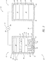
添付の図面中では、同一参照番号は類似の要素又は作用を示す。添付の図中の要素のサイズ及び相対位置は、必ずしもスケール通りには描かれていない。例えば種々の要素の形状及び角度はスケール通りには描かれていないし、これらの要素のいくつかは、添付の図面を見やすくするために随意に拡大され、配置される。さらに、図示される要素の特定の形状は、特定の要素の実際の形状に関する何らの情報を伝えることも意図されず、専ら図面中での認識を容易にするために選択されている。 In the accompanying drawings, identical reference numbers indicate similar elements or acts. The sizes and relative positions of elements in the attached figures are not necessarily drawn to scale. For example, the shapes and angles of the various elements are not drawn to scale, and some of these elements are arbitrarily enlarged and arranged to make the accompanying drawings easier to see. Further, the particular shape of the illustrated element is not intended to convey any information regarding the actual shape of the particular element and is selected solely to facilitate recognition in the drawings.
本明細書中に記載されるイオントフォレーシス装置は、貯蔵中の活性物質の安定性を取り扱う。特にこの装置は、希釈剤区画、活性物質区画及びその間に配置されるポリマー複合体層を含む区画化内部活性物質貯留槽を有している。ポリマー複合体層は、2つの区画間の仕切りとして作用する。活性物質は、希釈剤から離れて、安定溶液形態又は乾燥形態で、活性物質区画中に貯留され得る。イオントフォレーシス中、ポリマー複合体層は電流に応じて崩壊し、それにより生体界面への適用直前に活性物質を希釈剤と混合させる。この装置は、典型的には溶液相中で不安定であるか、又は特定溶媒中で安定であっても、貯蔵中、長時間、薬学的に許容可能な希釈剤と配合禁忌である活性物質を貯留し、投与するために特に適している。 The iontophoresis device described herein deals with the stability of the active substance during storage. In particular, the device has a compartmented internal active agent reservoir that includes a diluent compartment, an active agent compartment, and a polymer composite layer disposed therebetween. The polymer composite layer acts as a partition between the two compartments. The active substance can be stored in the active substance compartment in a stable solution form or in a dry form away from the diluent. During iontophoresis, the polymer composite layer collapses in response to current, thereby mixing the active agent with the diluent just prior to application to the biological interface. This device is typically unstable in solution phase, or active in active ingredients that are incompatible with pharmaceutically acceptable diluents for extended periods of time during storage, even if stable in a particular solvent Is particularly suitable for storing and administering.
下記において、或る種の特定の詳細は、種々の開示実施形態の十分な理解を提供するために説明される。しかしながら、実施形態は1つ又は複数のこれらの特定の詳細なしに、或いは他の方法、構成要素、材料等を用いて実行され得ると当業者は認識するだろう。その他の場合、制御装置に関連した既知の構造物、例えば電圧及び/又は電流調整器(これらに限定されない)は、当該実施形態の不必要に曖昧な記述を避けるために詳細に示されても記載されてもいない。 In the following description, certain specific details are set forth in order to provide a thorough understanding of various disclosed embodiments. However, one of ordinary skill in the art will recognize that the embodiments may be practiced without one or more of these specific details or using other methods, components, materials, and the like. In other cases, known structures associated with the controller, such as, but not limited to, voltage and / or current regulators may be shown in detail to avoid an unnecessarily ambiguous description of the embodiment. It is not described.
文脈から他の解釈が必要である場合を除いて、以下の明細書及び添付の特許請求の範囲全体を通して、「含む」という語及びその変形、例えば「含む(comprises)」及び「含む(comprising)」は、非限定で包括的な意味で、「包含するが、限定されない」と解釈されるべきである。 Unless the context requires otherwise, throughout the following specification and the appended claims, the word “comprising” and variations thereof, such as “comprises” and “comprising” "Is to be interpreted in a non-limiting and inclusive sense as" including but not limited to ".
本明細書全体を通して、「一実施形態」又は「1つの実施形態」という言及は、実施形態に関連して記載される特定の特徴、構造又は特質が少なくとも1つの実施形態に包含されるということを意味する。したがって本明細書全体を通して種々の箇所における「一実施形態における」又は「1つの実施形態における」という語句の出現は、必ずしもすべてが同一実施形態を指すわけではない。さらに、特定の特徴、構造物又は特質は、1つ又は複数の実施形態において任意の好適な様式で組合せられ得る。 Throughout this specification, reference to “one embodiment” or “one embodiment” means that a particular feature, structure, or characteristic described in connection with the embodiment is included in at least one embodiment. Means. Thus, the appearances of the phrases “in one embodiment” or “in one embodiment” in various places throughout this specification are not necessarily all referring to the same embodiment. Furthermore, the particular features, structures or characteristics may be combined in any suitable manner in one or more embodiments.
概して、イオントフォレーシス中は、荷電種又は非荷電種(例えば活性物質)は、透過性生体界面を通って下にある生物組織中に移動し得る。典型的には、イオントフォレーシス装置は、電気反発力及び電気浸透力の両方を生じる。荷電種に関しては、移動は主に、逆荷電作用側電極と荷電種との間の電気反発により駆動される。電気反発力のほかに、液体(例えば溶媒又は希釈液)の電気浸透流は、荷電種の輸送にも関与し得る。或る種の実施形態では、電気浸透溶媒流は、荷電種の移動を増強し得る第二の力である。非荷電種又は中性種に関しては、移動は主に、溶媒の電気浸透流により駆動される。 In general, during iontophoresis, charged or uncharged species (eg, active substances) can migrate through the permeable biological interface into the underlying biological tissue. Typically, iontophoresis devices produce both electrorepulsive and electroosmotic forces. With respect to charged species, the movement is driven primarily by electrical repulsion between the reverse charge working side electrode and the charged species. In addition to electrorepulsive forces, electroosmotic flow of liquids (eg, solvents or diluents) can also be involved in transporting charged species. In certain embodiments, electroosmotic solvent flow is a second force that can enhance the migration of charged species. For uncharged or neutral species, migration is driven primarily by the electroosmotic flow of the solvent.
本明細書中及び添付の特許請求の範囲で用いる場合、「ポリマー複合体」という用語は、一方のポリマーの電子欠損基と他方のポリマーの富電子基との間の集合水素結合のため、2つの親水性ポリマーにより形成される安定複合体を意味する。以下で詳細に考察される或る種の条件下では、複合体形成は熱力学的に好都合であり、多数の水素結合によって複合体に安定性を付与する。ポリマー構成成分の各々と異なり、複合体は水溶性ではない。 As used herein and in the appended claims, the term “polymer complex” refers to an assembled hydrogen bond between the electron deficient group of one polymer and the electron-rich group of the other polymer. It means a stable complex formed by two hydrophilic polymers. Under certain conditions, which are discussed in detail below, complex formation is thermodynamically favorable and imparts stability to the complex through multiple hydrogen bonds. Unlike each of the polymer components, the complex is not water soluble.
一実施形態では、ポリマー複合体を形成するための第一のポリマー構成成分は、各反復単位中に電子欠損基を含む。ポリマー複合体を形成するための第二のポリマー構成成分は、各反復単位中に富電子基を含む。水素結合により安定化されるポリマー複合体の例としては、ポリ((メタ)アクリル酸)及びポリ(アクリルアミド)の複合体、ポリ((メタ)アクリル酸)及びポリ(ビニルアルコール)の複合体、ポリ((メタ)アクリル酸)及びポリ(エチレングリコール)の複合体、ポリ((メタ)アクリル酸)及びポリ(N-ビニルピロリドン)の複合体並びにポリ((メタ)アクリル酸)及びポリ(エチルオキサゾリン)の複合体が挙げられるが、これらに限定されない。ポリ((メタ)アクリル酸)は当該技術分野で承認された表現であり、ポリ(アクリル酸)及びポリ(メタクリル酸)の両方を指す。 In one embodiment, the first polymer component for forming the polymer conjugate includes an electron deficient group in each repeating unit. The second polymer component for forming the polymer composite includes an electron rich group in each repeating unit. Examples of polymer composites stabilized by hydrogen bonding include poly ((meth) acrylic acid) and poly (acrylamide) composites, poly ((meth) acrylic acid) and poly (vinyl alcohol) composites, Poly ((meth) acrylic acid) and poly (ethylene glycol) composites, poly ((meth) acrylic acid) and poly (N-vinylpyrrolidone) composites, and poly ((meth) acrylic acid) and poly (ethyl) Oxazoline) complexes, but not limited thereto. Poly ((meth) acrylic acid) is an expression approved in the art and refers to both poly (acrylic acid) and poly (methacrylic acid).
一実施形態では、各ポリマー構成成分は、少なくとも5000の分子量を有する。別の実施形態では、各ポリマー構成成分は、少なくとも10000の分子量を有する。別の実施形態では、各ポリマー構成成分は、少なくとも50000の分子量を有する。 In one embodiment, each polymer component has a molecular weight of at least 5000. In another embodiment, each polymer component has a molecular weight of at least 10,000. In another embodiment, each polymer component has a molecular weight of at least 50000.
ポリマー複合体は、典型的には、第一のポリマー構成成分及び第二のポリマー構成成分から1:1比のそれぞれの反復単位で構成される。複合体は一般に、溶媒組成、pH及びイオン強度の狭い範囲内で水性媒質中で形成される。典型的には、複合体は、水素結合並びに疎水性相互作用の協同性により安定化され、即ち疎水性ポリマー主鎖は水からのそれらの集合的反発作用のために凝集する傾向がある。 The polymer composite is typically composed of a 1: 1 ratio of each repeating unit from the first polymer component and the second polymer component. The complex is generally formed in an aqueous medium within a narrow range of solvent composition, pH and ionic strength. Typically, the complexes are stabilized by hydrogen bonds as well as the cooperativity of hydrophobic interactions, i.e. the hydrophobic polymer backbones tend to aggregate due to their collective repulsion from water.
上記のように、複合体形成は、水性媒質のpH値により誘発され得る。典型的には、第二のポリマー構成成分の富電子基はpH変動に対して感受性であり、そして低pHでプロトン化され、高pHで脱プロトン化される。プロトン化形態は、第一のポリマー構成成分の電子欠損基と水素結合を形成して、安定化ポリマー複合体を提供する傾向がある。 As noted above, complex formation can be induced by the pH value of the aqueous medium. Typically, the electron-rich groups of the second polymer component are sensitive to pH fluctuations and are protonated at low pH and deprotonated at high pH. The protonated form tends to form a hydrogen bond with the electron deficient group of the first polymer component to provide a stabilized polymer complex.
複合体形成プロセスは、可逆的である。高pHでは、富電子基は脱プロトン化される。このプロセスは、水素結合を弱めるか又は排除する。水素結合の非存在下では、2つのポリマー構成成分は互いに解離するようになり、そして複合体は崩壊する。本明細書中で用いる場合、「臨界pH」とは、ポリマー複合体が不安定になるpH値又は範囲を指す。 The complex formation process is reversible. At high pH, electron-rich groups are deprotonated. This process weakens or eliminates hydrogen bonding. In the absence of hydrogen bonds, the two polymer components become dissociated from each other and the complex collapses. As used herein, “critical pH” refers to the pH value or range at which the polymer complex becomes unstable.
例えば1:1比の反復単位を有するポリ(アクリル酸)及びポリ(エチルオキサゾリン)は、pH5で水不溶性複合体を形成する。複合体は、同じpHで1ヶ月間安定なままである。複合体は、5.4より高いpHで直ちに溶解する。このプロセス及びそのメカニズムは、薬剤の制御放出のための電気浸食性ポリマーゲル(Electrically Erodible Polymer Gel For Controlled Release of Drugs), Kown, I.C., et al., Nature, Vol. 354, 291, 1991(この記載内容は参照によりその全体において本明細書中で援用される)に詳細に記載されている。 For example, poly (acrylic acid) and poly (ethyloxazoline) having a 1: 1 ratio of repeating units form a water-insoluble complex at pH 5. The complex remains stable for 1 month at the same pH. The complex dissolves immediately at a pH higher than 5.4. This process and its mechanism are described in Electrically Erodible Polymer Gels for Controlled Release of Drugs, Kown, IC, et al., Nature, Vol. 354, 291, 1991 (this The contents of the description are described in detail in the specification, which is incorporated herein by reference in its entirety.
有意には、ポリマー複合体の崩壊は、電場により誘発及び制御することができる。電場下では、水酸化物イオン(OH−)は水の電気分解により生成され、その間、水は水素ガス及び水酸化物に還元される。水酸化物イオンは、電解質中にも存在し得る。いずれにしても、水酸化物イオンの電気的な誘導による移動はポリマー複合体の局所pH環境を変えて、その崩壊をもたらす。 Significantly, the collapse of the polymer complex can be induced and controlled by an electric field. Under an electric field, hydroxide ions (OH − ) are generated by electrolysis of water, while water is reduced to hydrogen gas and hydroxide. Hydroxide ions can also be present in the electrolyte. In any case, the electrically induced migration of hydroxide ions changes the local pH environment of the polymer complex and causes its collapse.
本発明の装置のポリマー複合体層は、固体形態(例えば固体ディスク)又は予備膨潤ゲル形態をとり得る。それは、希釈剤区画から活性物質区画を分離するための仕切りとして役立つ。イオントフォレーシス中、水酸化物イオン(電気化学的に生成されるか又は電解質溶液中に存在する)は、ポリマー複合体層に移動して、その崩壊を生じる。ポリマー複合体仕切りが一旦排除されると、活性物質及び希釈剤は拡散して、生体界面を通って輸送される前に内部活性物質貯留槽内に過渡的溶液又は分散液を形成する。 The polymer composite layer of the device of the present invention can take a solid form (eg, a solid disk) or a pre-swelled gel form. It serves as a partition for separating the active substance compartment from the diluent compartment. During iontophoresis, hydroxide ions (electrochemically generated or present in the electrolyte solution) migrate to the polymer composite layer and cause its collapse. Once the polymer composite partition is removed, the active agent and diluent diffuse to form a transient solution or dispersion in the internal active agent reservoir before being transported through the biological interface.
「希釈剤」とは、本明細書中及び添付の特許請求の範囲で用いる場合、送達されるべき活性物質と相溶性である任意の溶媒又は溶媒系を指す。希釈剤自体は不活性であるが、生体界面を通して輸送する前に活性物質を調製するために必要なものである。例えば一実施形態では、活性物質は安定固体形態で貯留され、投与直前にのみ希釈剤と混和可能とされ得る。別の実施形態では、活性物質の安定前駆体は長期貯蔵に適した安定分散液中に懸濁され得る。前駆体は、希釈剤と混合されると、遊離活性物質を放出し得る。これは、活性物質が不安定であるか又は短寿命であり、投与直前に生成されなければならない場合に特に有用である。 “Diluent” as used herein and in the appended claims refers to any solvent or solvent system that is compatible with the active agent to be delivered. The diluent itself is inert, but is necessary to prepare the active substance prior to transport through the biological interface. For example, in one embodiment, the active agent may be stored in a stable solid form and only miscible with the diluent just prior to administration. In another embodiment, the stable precursor of the active substance can be suspended in a stable dispersion suitable for long-term storage. The precursor may release free active substance when mixed with a diluent. This is particularly useful when the active substance is unstable or short-lived and must be produced just prior to administration.
或る種の実施形態では、活性物質は、正味電荷を得るために希釈剤中に溶解され、さらに重要なことに、イオン化され得る。荷電活性物質は主に、イオントフォレーシス中に電気反発作用により駆動され得る。他の実施形態では、中性活性物質は、希釈剤の存在下においても中性のままである。中性活性物質は、本明細書中でさらに詳細に記載されるように、希釈剤の電気浸透流を介して輸送され得る。 In certain embodiments, the active agent can be dissolved in a diluent to obtain a net charge and, more importantly, can be ionized. Charged active materials can be driven primarily by electrical repulsion during iontophoresis. In other embodiments, the neutral active substance remains neutral in the presence of a diluent. Neutral actives can be transported via an electroosmotic flow of diluent, as described in further detail herein.
典型的には、希釈剤は水性である。希釈剤はさらに、生理学的適合性イオン、例えばナトリウム、カリウム、塩化物及びリン酸塩を含み得る。希釈剤は、水溶性有機溶媒、例えばエタノール及びアセトンも含み得る。 Typically, the diluent is aqueous. Diluents can further include physiologically compatible ions such as sodium, potassium, chloride and phosphate. Diluents can also include water-soluble organic solvents such as ethanol and acetone.
「活性物質(active agent)」という用語は、任意の宿主、動物、脊椎動物又は無脊椎動物、例えば魚類、哺乳類、両生類、爬虫類、鳥類及びヒトからの生物学的応答を引き出す化合物、分子又は治療物質を指す。活性物質の例としては、治療用物質、薬学的物質、調合薬(例えば薬剤、治療用化合物、薬学的塩等)、非調合薬(例えば化粧用物質等)、ワクチン、免疫学的作用物質、局所麻酔薬又は全身麻酔薬又は鎮痛剤、抗原又はタンパク質又はペプチド、例えばインスリン、化学療法薬、抗腫瘍薬が挙げられる。 The term “active agent” refers to a compound, molecule or therapy that elicits a biological response from any host, animal, vertebrate or invertebrate, such as fish, mammals, amphibians, reptiles, birds and humans. Refers to a substance. Examples of active substances include therapeutic substances, pharmaceutical substances, pharmaceutical preparations (eg drugs, therapeutic compounds, pharmaceutical salts etc.), non-preparation medicines (eg cosmetic substances etc.), vaccines, immunologically active substances, Local anesthetics or general anesthetics or analgesics, antigens or proteins or peptides such as insulin, chemotherapeutic drugs, antitumor drugs.
いくつかの実施形態では、「活性物質」という用語はさらに、活性物質、並びにその薬理学的活性塩、薬学的に許容可能な塩、プロドラッグ、代謝産物、類似体等を指す。いくつかのさらなる実施形態では、活性物質としては、少なくとも1つのイオン性、陽イオン性、陰イオン性、イオン化可能及び/又は中性の治療薬及び/又はその薬学的に許容可能な塩が挙げられる。 In some embodiments, the term “active agent” further refers to the active agent, as well as pharmacologically active salts, pharmaceutically acceptable salts, prodrugs, metabolites, analogs, and the like thereof. In some further embodiments, the active agent includes at least one ionic, cationic, anionic, ionizable and / or neutral therapeutic agent and / or a pharmaceutically acceptable salt thereof. It is done.
いくつかの実施形態では、活性物質は、正に荷電され、及び/又は水性媒質中で正電荷を生じ得る1つ又は複数の「陽イオン性活性物質」を含み得る。例えば多数の生物学的活性物質は、陽性イオンに容易に転化可能であるか又は水性媒質中で正荷電イオン及び対イオンに解離し得る官能基を有する。その他の活性物質は、分極されるか又は分極可能であり、即ち別の部分に比べてある部分で極性を示す。例えばアミン基を有する活性物質は、典型的には、適切なpHにおいてプロトン化アミンとも呼ばれる4級アンモニウム陽イオン(−NR3H+)の形態を取る。以下に述べるように、大半の「陽イオン」タイプの鎮痛剤および麻酔薬を含む多くの活性物質はアミン基を有する。これらのアミン基はイオントフォレーシス装置においてプロトン化された形態で存在し得る。 In some embodiments, the active agent can include one or more “cationic active agents” that are positively charged and / or can generate a positive charge in an aqueous medium. For example, many biologically active substances have functional groups that can be easily converted to positive ions or dissociated into positively charged and counter ions in aqueous media. Other active substances are polarized or polarizable, i.e. exhibit polarity in one part compared to another part. For example, an active substance having an amine group typically takes the form of a quaternary ammonium cation (—NR 3 H + ), also referred to as a protonated amine, at a suitable pH. As described below, many active substances, including most “cationic” type analgesics and anesthetics, have amine groups. These amine groups can be present in protonated form in an iontophoresis device.
他の実施形態では、活性物質は、水性媒体中で容易に負電荷を有するように変化し、又は、負荷電のイオン及び対イオンに解離することができる官能基を有し得る。負に荷電した活性物質は、「陰イオン活性物質」とも呼ばれる。例えば、カルボン酸基を有する活性物質は、固体状態では典型的には−COOHの形態を取り、適切なpHの水性媒体中でCOO−に解離する。 In other embodiments, the active agent can be easily modified to have a negative charge in an aqueous medium or have a functional group that can dissociate into negatively charged ions and counterions. Negatively charged active substances are also referred to as “anionic active substances”. For example, the active substance having a carboxylic acid group, in the solid state, typically take the form of -COOH, COO in an aqueous medium suitable pH - dissociated into.
他の活性物質は、分極化され、或いは、分極化可能であり得、従って、或る部分が他の部分に比較して極性を示し得る。 Other active substances may be polarized or polarizable, and thus some parts may exhibit polarity compared to other parts.
「活性物質」という用語は、電気浸透圧流により送達され得る電気的に中性な作用物質、分子又は化合物も指す。電気的に中性な作用物質は、典型的には、例えば電気泳動中の溶媒の流れにより運ばれる。したがって適切な活性物質の選択は、当業者の知識内である。 The term “active agent” also refers to an electrically neutral agent, molecule or compound that can be delivered by electroosmotic flow. The electrically neutral agent is typically carried by a solvent stream, for example during electrophoresis. The selection of the appropriate active substance is therefore within the knowledge of the person skilled in the art.
いくつかの実施形態において、1つ又は複数の活性物質は、鎮痛薬、麻酔薬、麻酔薬ワクチン、抗生剤、アジュバント、免疫学的アジュバント、免疫原、寛容原、アレルゲン、トル様受容体アゴニスト、トル様受容体アンタゴニスト、免疫アジュバント、免疫調節物質、免疫応答物質、免疫刺激物質、特異的免疫刺激物質、非特異的免疫刺激物質、及び免疫抑制物質、又はこれらの組合せから選択されてもよい。 In some embodiments, the one or more active agents are an analgesic, anesthetic, anesthetic vaccine, antibiotic, adjuvant, immunological adjuvant, immunogen, tolerogen, allergen, toll-like receptor agonist, Toll-like receptor antagonists, immunoadjuvants, immunomodulators, immune responders, immunostimulators, specific immunostimulators, non-specific immunostimulators, and immunosuppressants, or combinations thereof may be selected.
このような活性物質の非限定的な例としては、リドカイン、アルチカイン及び−カイン群の他のもの、モルヒネ、ヒドロモルホン、フェンタニル、オキシコドン、ヒドロコドン、ブプレノルフィン、メタドン及び同様のオピオイドアゴニスト、コハク酸スマトリプタン、ゾルミトリプタン、ナラトリプタンHCl、安息香酸リザトリプタン、リンゴ酸アルモトリプタン、コハク酸フロバトリプタン及び他の5−ヒドロキシトリプタミン1受容体サブタイプアゴニスト、レシキモド(resiquimod)、イミキモド(imiquidmod)並びに同様のTLR7及びTLR8のアゴニスト及びアンタゴニスト、ドンペリドン、塩酸グラニセトロン、オンダンセトロン及びこのような鎮吐剤、酒石酸ゾルピデム及び同様の睡眠剤、L−ドーパ及び他の抗パーキンソン病薬、アリピプラゾール、オランザピン、クエチアピン、リスペリドン、クロザピン及びジプラシドン並びに他の精神安定剤、エクセナチド等の糖尿病薬、並びに肥満及び他の疾患の治療用のペプチド及びタンパク質が挙げられる。 Non-limiting examples of such active agents include those of the lidocaine, articaine and -caine groups, morphine, hydromorphone, fentanyl, oxycodone, hydrocodone, buprenorphine, methadone and similar opioid agonists, sumatriptan succinate, Zolmitriptan, naratriptan HCl, rizatriptan benzoate, almotriptan malate, frovatriptan succinate and other 5-hydroxytryptamine 1 receptor subtype agonists, resiquimod, imiquimod, and similar TLR7 And agonists and antagonists of TLR8, domperidone, granisetron hydrochloride, ondansetron and such antiemetics, zolpidem tartrate and similar sleeping agents, L-dopa and other antiparkinson Drugs, aripiprazole, olanzapine, quetiapine, risperidone, clozapine and ziprasidone as well as other tranquilizers, diabetes mellitus drugs such as exenatide, as well as peptides and proteins for treatment of obesity and other diseases.
麻酔性活性物質又は鎮痛剤のさらなる非限定例としては、アンブカイン、アメトカイン、p−アミノ安息香酸イソブチル、アモラノン、アモキセカイン、アミロカイン、アプトカイン、アザカイン、ベンカイン、ベノキシネート、ベンゾカイン、N,N-ジメチルアラニルベンゾカイン、N,N-ジメチルグリシルベンゾカイン、グリシルベンゾカイン、β−アドレナリン受容体アンタゴニストベトキシカイン、ブメカイン、ブピバカイン(bupivicaine)、レボブピバカイン(levobupivicaine)、ブタカイン、ブタンベン、ブタニリカイン、ブテタミン、ブトキシカイン、メタブトキシカイン、カルビゾカイン(carbizocaine)、カルチカイン、セントブクリジン(centbucridine)、セパカイン(cepacaine)、セタカイン(cetacaine)、クロロプロカイン、コカエチレン、コカイン、プソイドコカイン、シクロメチカイン、ジブカイン、ジメチソキン、ジメトカイン、ジペロドン、ジクロニン、エコグニン(ecognine)、エコゴニジン(ecogonidine)、アミノ安息香酸エチル、エチドカイン、ユープロシン、フェナルコミン、フォモカイン、ヘプタカイン、ヘキサカイン、ヘキソカイン、ヘキシルカイン、ケトカイン、ロイシノカイン、レボキサドロール、リグノカイン、ロツカイン、マーカイン、メピバカイン、メタカイン、塩化メチル、ミルテカイン、ネパイン、オクタカイン、オルトカイン、オキセタゼイン、パレントキシカイン(parenthoxycaine)、ペンタカイン、フェナシン、フェノール、ピペロカイン、ピリドカイン、ポリドカノール、ポリカイン、プリロカイン、プラモキシン、プロカイン(ノボカイン(登録商標))、ヒドロキシプロカイン、プロパノカイン、プロパラカイン、プロピポカイン、プロポキシカイン、ピロカイン、カタカイン、リノカイン、リソカイン、ロドカイン、ロピバカイン、サリチルアルコール、テトラカイン、ヒドロキシテトラカイン、トリカイン(tolycaine)、トラペンカイン、トリカイン(tricaine)、トリメカイン、トロパコカイン、ゾラミン、これらの薬学的に許容可能な塩、及びこれらの混合物が挙げられる。 Further non-limiting examples of anesthetic active substances or analgesics include ambucaine, amethocaine, isobutyl p-aminobenzoate, amoranone, amoxecaine, amylocaine, aptocaine, azacaine, bencaine, benoxinate, benzocaine, N, N-dimethylalanylbenzocaine , N, N-dimethylglycylbenzocaine, glycylbenzocaine, β-adrenergic receptor antagonist betoxycaine, bumecaine, bupivicaine, levobupivicaine, butacaine, butaneben, butanilicaine, butetamine, butoxycaine, metabutoxy Cain, carbizocaine, carticaine, centbucridine, cepacaine, cetacaine, chloroprocaine, cocache Len, cocaine, pseudococaine, cyclomethicaine, dibucaine, dimethoquine, dimethokine, diperodon, dichronin, ecognine, ecogonidine, ethyl aminobenzoate, etidocaine, euprocine, phenalkamine, fomocainecaine, heptacaine , Hexylcaine, Ketocaine, Leucinocaine, Levoxadrol, Lignocaine, Rotocaine, Markine, Mepivacaine, Metacaine, Methyl chloride, Miltecaine, Nepain, Octacaine, Orthocaine, Oxetazeine, Parenthoxycaine, Pentaine, Pyrenecaine, Phenocaine, Penocaine, Poldocanol, polycaine, prilocaine, pramoxine, procaine (Novokai) (Registered trademark), hydroxyprocaine, propanocaine, propalacaine, propipocaine, propoxycaine, pilocaine, katakane, linocaine, lysocaine, rhodocaine, ropivacaine, salicyl alcohol, tetracaine, hydroxytetracaine, tricaine (tolycaine), trapecaine, tricaine tricaine), trimecaine, tropopacaine, zolamine, pharmaceutically acceptable salts thereof, and mixtures thereof.
上記のように、本明細書中に記載される装置は、それらが任意の長時間、溶液相中に保持される場合、そうでなければ不安定である活性物質の送達に特に適している。一実施形態によれば、このような活性物質は、固体形態で貯留され、そしてポリマー複合体層又は仕切りにより希釈剤から分離され得る。電場に応じて、ポリマー複合体仕切りは崩壊し、活性物質を希釈剤と混合させて、起電力及び/又は電流下で輸送可能な活性物質を提供する。 As mentioned above, the devices described herein are particularly suitable for delivery of active substances that are otherwise unstable if they are held in solution phase for any length of time. According to one embodiment, such active agents can be stored in solid form and separated from the diluent by a polymer composite layer or partition. Depending on the electric field, the polymer composite partition collapses and the active substance is mixed with the diluent to provide an active substance that can be transported under electromotive force and / or current.
本明細書中及び添付の特許請求の範囲で用いる場合、「膜」という用語は、透過性である場合も、透過性でない場合もある層、障壁、又は物質を意味する。別記しない限り、膜は、固体、液体又はゲルの形態をとり得るし、そして異なる格子又は架橋構造を有しても、有しなくてもよい。 As used herein and in the appended claims, the term “membrane” means a layer, barrier, or substance that may or may not be permeable. Unless stated otherwise, the membrane may take the form of a solid, liquid or gel and may or may not have a different lattice or cross-linked structure.
本明細書中及び添付の特許請求の範囲で用いる場合、「イオン選択膜」という用語は、イオンに対して実質的に選択性であり、或る種のイオンを通すが、他のイオンの通過を遮断する膜を意味する。イオン選択膜は、例えば電荷選択膜の形態をとり得るか、或いは半透性膜の形態をとり得る。 As used herein and in the appended claims, the term “ion-selective membrane” is substantially selective to ions and allows passage of certain ions but passage of other ions. Means a membrane that blocks The ion selective membrane can take the form of a charge selective membrane, for example, or it can take the form of a semi-permeable membrane.
本明細書中及び添付の特許請求の範囲で用いる場合、「イオン選択膜」又は「電荷選択膜」という用語は、主にイオンにより担持される極性又は電荷に基づいて、イオンを実質的に通過及び/又は実質的に遮断する膜を意味する。電荷選択膜は典型的にはイオン交換膜を指し、そしてこれらの用語は、本明細書中で並びに添付の特許請求の範囲において互換的に用いられる。電荷選択膜又はイオン交換膜は、陽イオン交換膜、陰イオン交換膜及び/又は両極性膜の形態をとり得る。陽イオン交換膜は、陽イオンの通過のみを可能にし、そして陰イオンを実質的に遮断する。市販の陽イオン交換膜の例としては、NEOSEPTA、CM-1、CM-2、CMX、CMS及びCMB(株式会社トクヤマ)の呼称で入手可能なものが挙げられる。逆に陰イオン交換膜は、陰イオンの通過のみを可能にし、そして陽イオンを実質的に遮断する。市販の陰イオン交換膜の例としては、NEOSEPTA、AM-1、AM-3、AMX、AHA、ACH及びACS(同じく株式会社トクヤマ)の呼称で入手可能なものが挙げられる。 As used herein and in the appended claims, the terms “ion-selective membrane” or “charge-selective membrane” refer to substantially passing ions based primarily on the polarity or charge carried by the ions. And / or a membrane that substantially blocks. Charge selective membranes typically refer to ion exchange membranes, and these terms are used interchangeably herein and in the appended claims. The charge selective membrane or ion exchange membrane may take the form of a cation exchange membrane, an anion exchange membrane and / or a bipolar membrane. The cation exchange membrane allows only the passage of cations and substantially blocks anions. Examples of commercially available cation exchange membranes include those available under the names NEOSEPTTA, CM-1, CM-2, CMX, CMS and CMB (Tokuyama Corporation). Conversely, an anion exchange membrane allows only the passage of anions and substantially blocks cations. Examples of commercially available anion exchange membranes include those available under the names NEOSEPTA, AM-1, AM-3, AMX, AHA, ACH and ACS (also Tokuyama Corporation).
本明細書及び添付の特許請求の範囲で用いる場合、「両極性膜」という用語は、2つの異なる電荷又は極性に対して選択的である膜を意味する。別記しない限り、両極性膜は、一体膜構造又は多重膜構造の形態をとり得る。一体膜構造は、陽イオン交換物質又は基を含む第一の部分、並びに陰イオン交換物質又は基を含む第一の部分と向き合った第二の部分を包含し得る。多重膜構造(例えば二重皮膜構造)は、陰イオン交換膜に付着か又は結合される陽イオン交換膜により形成され得る。陽イオン交換膜及び陰イオン交換膜は最初に異なる構造物として出発し、そしてその結果生じる両極性膜の構造中でそれらの弁別性を保持し得るか、又は保持し得ない。 As used herein and in the appended claims, the term “ambipolar membrane” means a membrane that is selective for two different charges or polarities. Unless stated otherwise, the bipolar membrane may take the form of a monolithic membrane structure or a multi-membrane structure. The monolithic membrane structure can include a first portion that includes a cation exchange material or group, and a second portion that faces the first portion that includes an anion exchange material or group. Multi-membrane structures (eg, double membrane structures) can be formed by cation exchange membranes that are attached to or bound to an anion exchange membrane. Cation and anion exchange membranes initially start as different structures and may or may not retain their discrimination in the resulting bipolar membrane structure.
本明細書及び添付の特許請求の範囲で用いる場合、「半透性膜」という用語は、イオンのサイズ又は分子量に基づいて実質的に選択的である膜を意味する。したがって半透性膜は、第一の分子量又はサイズのイオンを実質的に通す一方で、第一の分子量又はサイズより大きい第二の分子量又はサイズのイオンの通過を実質的に遮断する。 As used herein and in the appended claims, the term “semipermeable membrane” means a membrane that is substantially selective based on the size or molecular weight of the ions. Thus, the semipermeable membrane substantially passes ions of a first molecular weight or size while substantially blocking the passage of ions of a second molecular weight or size that is larger than the first molecular weight or size.
本明細書及び添付の特許請求の範囲で用いる場合、「多孔性膜」という用語は、問題のイオンに関して実質的に選択的ではない膜を意味する。例えば多孔性膜は、極性に基づいて実質的に選択的でなく、且つ対象の要素又は化合物の分子量又はサイズに基づいて実質的に選択的でないものである。 As used herein and in the appended claims, the term “porous membrane” means a membrane that is not substantially selective with respect to the ions in question. For example, a porous membrane is one that is not substantially selective based on polarity and not substantially selective based on the molecular weight or size of the element or compound of interest.
本明細書及び添付の特許請求の範囲で用いる場合、「貯留槽」という用語は、液体状態、固体状態、気体状態、混合状態及び/又は遷移状態で、要素又は化合物を担持するための任意の形態のメカニズムを意味する。例えば別記しない限り、貯留槽は、一構造物により形成される1つ又は複数のキャビティを含み得るし、そしてこのようなものが少なくとも一時的に要素又は化合物を担持し得る場合には、1つ又は複数のイオン交換膜、半透性膜、多孔性膜及び/又はゲルを含み得る。典型的には、貯留槽は、生体界面への起電力及び/又は電流によるこのような作用物質の放出の前に、複数の活性物質を担持するのに役立つ。上記のように、本明細書中に記載される装置は、区画化される内部活性物質貯留槽を包含する。貯留槽は、電解質溶液も担持し得る。 As used herein and in the appended claims, the term “reservoir” refers to any element for carrying an element or compound in a liquid state, a solid state, a gas state, a mixed state and / or a transition state. Means the mechanism of form. For example, unless otherwise indicated, a reservoir may include one or more cavities formed by a structure, and one such if such can at least temporarily carry an element or compound. Or it may comprise a plurality of ion exchange membranes, semipermeable membranes, porous membranes and / or gels. Typically, the reservoir serves to carry a plurality of active substances prior to the release of such agents by electromotive force and / or current to the biological interface. As noted above, the devices described herein include compartmentalized internal active substance reservoirs. The reservoir can also carry an electrolyte solution.
本明細書中で提示される見出しは、便宜上に過ぎず、当該実施形態の範囲又は意味を説明するものではない。 The headings presented herein are for convenience only and do not explain the scope or meaning of the embodiments.
図1〜図4は、それぞれ作用側電極構造体12及び対向電極構造体14を含むイオントフォレーシス装置10を示す。それらは、一例示的実施形態によりイオントフォレーシスを介して、生体界面18(図3及び図4)、例えば皮膚又は粘膜の一部に作用側電極構造体12中に含有される活性物質を供給するように動作可能な電源16に電気的に接続される。
1 to 4 show an
図1に例示される実施形態では、作用側電極構造体12は、作用側電極構造体12の内部20から外部22に、作用側電極要素24、電解質28を貯留する任意の電解質貯留槽26、任意の内部イオン選択膜30、希釈剤59を有する第一の区画53、活性物質36を収容する第二の区画57及び第一の区画と第二の区画との間に配置されるポリマー複合体層55を有する内部活性物質貯留槽34、付加的活性物質40を任意に貯蔵する任意の最外部イオン選択膜38、最外部イオン選択膜38の外表面44により担持される任意のさらなる活性物質42、並びに外部リリースライナー46を含む。上記の要素又は構造の各々を、以下で詳細に考察する。
In the embodiment illustrated in FIG. 1, the working
作用側電極要素24は、電源16の第一の電極16aと接続され、そして作用側電極構造体12に配置されて、起電力又は電流を印加して、作用側電極構造体12の種々の他の構成成分を介して活性物質36、40、42を輸送する。図1において、作用側電極要素は陰極(cathode)であり、そして活性物質36、40及び42は負に荷電される。
The working
作用側電極要素24は、種々の形態をとり得る。一実施形態では、この装置は、有益には、炭素ベースの作用側電極要素24を用い得る。このようなものは、例えば多重層、例えば炭素を含むポリマーマトリクス及び炭素繊維又は炭素繊維紙を含む導電性シートを含み、例えば同一出願人による係属中特願2004/317317号公報(2004年10月29日提出)に記載されている。炭素ベースの電極は、それら自体が電気化学反応を受けないか又はそれに関与しないという意味の不活性電極である。したがって不活性電極は、腐蝕又は枯渇されることなく電流を分配し、そして水の電気分解により電流を伝導する、即ち、水の還元又は酸化によりイオンを生成する。不活性電極の付加的例としては、ステンレススチール(steal)、金、白金又は黒鉛が挙げられる。
The working
電解質貯留槽26は、種々の形態、例えば電解質28を保持し得る任意の構造をとり、そしていくつかの実施形態では、例えば電解質28がゲル、半固体又は固体形態である場合、電解質28自体でさえあり得る。例えば電解質貯留槽26は、特に電解質28が液体である場合、パウチ又はその他の容器、孔、キャビティ又は隙間を有する膜の形態をとり得る。
The
一実施形態では、電解質28は、イオン性構成成分又はイオン化可能構成成分を水性媒質中に含み、これは、作用側電極要素に向けて、又はそれから離れて電流を伝達し得る。適切な電解質としては、例えば塩の水溶液が挙げられる。好ましくは電解質28は、生理学的イオン、例えばナトリウム、カリウム、クロリド及びホスフェートの塩を含む。
In one embodiment, the
上記のように、電解質28は、貯留槽26内に収容される水溶液の形態をとるか、或いは相当量の水を保持し得るヒドロゲル又は親水性ポリマー中の分散液の形態であり得る。例えば適切な電解質は、0.5Mフマル酸二ナトリウム:0.5Mポリ(アクリル酸)の溶液の形態をとり得る。
As described above, the
内部イオン選択膜30は一般に、このような膜が用いられるべきである場合、電解質28及び内部活性物質貯留槽34を分離するように配置される。内部イオン選択膜30は、電荷選択膜の形態をとり得る。例えば活性物質36、40、42が負荷電活性物質を含むため、内部イオン選択膜30は、陽イオンを実質的に通し、そして陰イオン性活性物質を実質的に遮断するように選択的である陽イオン交換膜の形態をとり得る。内部イオン選択膜30は、有益には、電解質28と内部活性物質貯留槽34との間の望ましくない要素又は化合物の移動を防止し得る。例えば内部イオン選択膜30は、電解質28からの塩化物(Cl−)イオンの移動を防止又は阻害し、それによりイオントフォレーシス装置10の移動速度及び/又は生物学的適合性を増大し得る。
The internal ion
内部活性物質貯留槽34は一般に、内部イオン選択膜30と最外部イオン選択膜38との間に配置される。内部活性物質貯留槽34は、種々の形態、例えば活性物質36を一時的に保持し得る任意の構造をとり得る。例えば内部活性物質貯留槽34は、特に活性物質36が液体である場合、パウチ又はその他の容器、孔、キャビティ又は隙間を有する膜の形態をとり得る。内部活性物質貯留槽34はさらに、希釈剤59を有する第一の区画53、複数の活性物質36を有する第二の区画57、並びに第一の区画53と第二の区画57との間に配置されるポリマー複合体層55を包含する。ポリマー複合体層55は、第一の区画及び第二の区画を分離する仕切り又は境界を形成する。層55の崩壊時に、第一の区画及び第二の区画のそれぞれの内容物、即ち希釈剤59及び活性物質36は混合される。
The internal
希釈剤は貯蔵中、ポリマー複合体が不安定になり得る臨界pHより低いpHに緩衝溶液により保持され得る。一実施形態では、希釈剤は水を含む。電場の印加下で、希釈剤区画53中の水は電気分解され、そして作用側電極構造体12(陰極)中の水の還元の電気化学的産物として、水酸化物イオンが生成される。水酸化物イオンは、電気反発作用のため、陰極12から離れて移動する。それらはさらに、ポリマー複合体層55の局所的環境中のpHの増大を生じる。ポリマー複合体の水素結合は弱められ、層55は崩壊する。その結果、活性物質36及び希釈剤59は混合され、そして活性物質36は電気反発力及び/又は電気浸透力下で生体界面に向けて移動する。
The diluent can be held by the buffer solution during storage at a pH below the critical pH at which the polymer complex can become unstable. In one embodiment, the diluent includes water. Under the application of an electric field, the water in
任意に、最外部イオン選択膜38は、作用側電極貯留槽24から作用側電極構造体12を通って一般的に向かい合って配置され得る。最外部膜38は、図1〜図4に図示した実施形態のように、イオン交換膜の形態をとることができ、当該イオン選択膜38の孔48(図を分かりやすくするために図1及び図2では1つだけが示されている)はイオン交換物質又は基50(図を分かりやすくするために図1〜図4では3つだけが示されている)を有している。電気浸透力又は電流の影響下では、イオン交換物質又は基50は選択的に、活性物質36、40と同じ極性を有するイオンを実質的に通す一方で、反対極性を有するイオンを実質的に遮断する。したがって最外部イオン交換膜38は、電荷選択的である。活性物質36、40、42が陰イオンである場合、最外部イオン選択膜38は陰イオン交換膜の形態をとり、したがって陰イオン性活性物質の通過を許容する一方で、生体界面、例えば皮膚に存在する陽イオンの逆流を遮断する。
Optionally, the outermost ion
最外部イオン選択膜38は、任意に活性物質40を貯蔵し得る。特に、イオン交換基又は物質50は、起電力又は電流の非存在下で活性物質の極性と同じ極性を有するイオンを一時的に保持し、そして起電力又は電流の影響下で同様の極性又は電荷を有する代用イオンと置き換えられる場合、それらのイオンを実質的に放出する。
The outermost ion
代替的には、最外部イオン選択膜38は、サイズにより選択的である半透性膜又は微小孔膜の形態をとり得る。いくつかの実施形態では、このような半透性膜は有益には、例えば外部リリースライナー46が使用前に除去されるまで、活性物質40を担持するために除去的に取り外し可能な外部リリースライナー46を用いることにより、活性物質40を貯蔵し得る。
Alternatively, the outermost ion
最外部イオン選択膜38は、付加的活性物質40、例えばイオン化した又はイオン化可能な薬剤又は治療薬、及び/又は、分極化された又は分極化可能な薬剤又は治療薬を任意に予備装荷され得る。最外部イオン選択膜38がイオン交換膜である場合、相当量の活性物質40が最外部イオン選択膜38の孔(又はキャビティ、隙間)48中のイオン交換基50と結合し得る。
The outermost ion
物質50のイオン交換基と結合できない活性物質42は、さらなる活性物質42として最外部イオン選択膜38の外表面44に付着し得る。代替的には又は付加的には、さらなる活性物質42は、例えば噴霧、フラッディング、コーティングにより、静電的に、蒸着により、及び/又は別のやり方で、最外部イオン選択膜38の外表面44の少なくとも一部の上に積極的に堆積される及び/又はそれに付着され得る。いくつかの実施形態では、さらなる活性物質42は、異なる層52を形成するために外表面44を十分に被覆し及び/又は十分な厚みを有し得る。他の実施形態では、さらなる活性物質42は、このような用語の慣用的意味で層を構成することについては、容積、厚み又は被覆面積において十分であるというわけではない。
The
活性物質42は、種々の高濃縮形態、例えば固体形態、ほぼ飽和した溶液形態又はゲル形態で堆積され得る。固体形態である場合、水和の供給源が提供され、作用側電極構造体12に組込まれるか、又は使用直前にその外部から適用され得る。
The
いくつかの実施形態では、活性物質36、付加的活性物質40及び/又はさらなる活性物質42は、同一又は類似の組成物又は要素であり得る。他の実施形態では、活性物質36、付加的活性物質40、及び/又はさらなる活性物質42は、互いに異なる組成物又は要素であり得る。したがって第一の型の活性物質が内部活性物質貯留槽34中に保存され得る一方で、第二の型の活性物質は最外部イオン選択膜38中に貯蔵され得る。このような実施形態では、第一の型又は第二の型の活性物質のいずれかが、さらなる活性物質42として最外部イオン選択膜38の外表面44上に堆積され得る。代替的には、第一の型及び第二の型の活性物質の混合物がさらなる活性物質42として最外部イオン選択膜38の外表面44上に堆積され得る。さらにそれに代わるものとして、第三の型の活性物質の組成物又は要素が、さらなる活性物質42として最外部イオン選択膜38の外表面44上に堆積され得る。別の実施形態では、第一の型の活性物質が活性物質36として内部活性物質貯留槽34中に保存され、そして付加的活性物質40として最外部イオン選択膜38中に貯蔵され得る一方で、第二の型の活性物質はさらなる活性物質42として最外部イオン選択膜38の外表面44上に堆積され得る。典型的には、1つ又は複数の異なる活性物質が用いられる実施形態では、活性物質36、40、42はすべて、共通の極性を有し、活性物質36、40、42が互いに競合しないようにする。他の組合せも可能である。
In some embodiments,
外部リリースライナーは一般に、最外部イオン選択膜38の外表面44により保有されるさらなる活性物質42の上に重なるか又はそれを覆って配置され得る。外部リリースライナー46は、起電力又は電流の印加前に、貯蔵中、さらなる活性物質42及び/又は最外部イオン選択膜38を保護し得る。外部リリースライナー46は、耐水性物質製の選択的に取り外し可能なライナー、例えば感圧性接着剤に一般的に関連するリリースライナーであり得る。図1、2では内部リリースライナーが示され、図3、4では除去されていることに留意されたい。
The outer release liner can generally be placed over or over a further
界面結合媒質(示されていない)は、電極構造体と生体界面18との間に用いられ得る。界面結合媒質は、例えば接着剤及び/又はゲルの形態をとり得る。ゲルは、例えば水和ゲルの形態をとり得る。適切な生体接着性ゲルの選択は、当業者の知識内である。
An interface coupling medium (not shown) can be used between the electrode structure and the
図2に示される実施形態では、作用側電極要素24は陽極(anode)である。この実施形態では、希釈剤区画53と活性物質区画57はポリマー複合体槽55に対する相対位置が切り替えられる。電場下において、希釈剤区画53に存在する水酸化物イオンは陽極に引き寄せられ、これによりポリマー複合体層55の近傍のpHの増加が引き起こされる。この実施形態では、活性物質は、希釈剤と混合した後に好ましくは陽イオンとなる。
In the embodiment shown in FIG. 2, the working
図3、4に示される実施形態では、生体界面38が最外部イオン選択膜38の外表面44と接触した状態で示されている。
In the embodiment shown in FIGS. 3 and 4, the
図3及び図4は更に対向電極構造体を示しており、当該対向電極構造体は、対向電極構造体14の内部64から外部66に向けて順に、対向電極要素68、電解質72を保存する電解質貯留槽70、内部イオン選択膜74、緩衝物質78を保存する任意の緩衝物質貯留槽76、任意の最外部イオン選択膜80、及び任意の外部リリースライナー82を有する。
FIGS. 3 and 4 further show a counter electrode structure. The counter electrode structure stores an
対向電極要素68は、電源16の第二の電極16bと電気的に結合され、第二の電極16bは第一の電極16aと逆の極性を有する。従って、対向電極要素68は、図1の装置では陰極であり、図2の装置では陽極である。一実施形態では、対向電極要素68は不活性電極である。例えば対向電極要素68は、上記の炭素ベースの電極要素であり得る。
The
電解質貯留槽70は、種々の形態、例えば電解質72を保持し得る任意の構造をとり、そしていくつかの実施形態では、例えば電解質72がゲル形態、半固体形態又は固体形態である場合、電解質72自体でさえあり得る。例えば電解質貯留槽70は、特に電解質72が液体である場合、パウチ又はその他の容器、或いは孔、キャビティ又は隙間を有する膜の形態をとり得る。
The
電解質72は一般に、対向電極要素68と、対向電極要素68に隣接した最外部イオン選択膜80との間に配置される。上記のように、電解質72は、イオンを提供するか又は電荷を供与して、対向電極要素68上の気泡(電極の極性によって、例えば水素又は酸素)の形成を防止又は阻害し、そして酸又は塩基の形成を防止又は阻害するか、或いはそれを中和し、これにより効率が高められ、及び/又は、生体界面18における刺激発生の可能性が低減され得る。
The
内部イオン選択膜74は、電解質72と緩衝物質78との間に、及び/又は電解質72を緩衝物質78から分離するよう配置される。内部イオン選択膜74は、電荷選択膜、例えば第一の極性又は電荷を有するイオンの通過を実質的に可能にするが一方で、第二の反対極性を有するイオン又は電荷の通過を実質的に遮断する図示したイオン交換膜の形態をとり得る。内部イオン選択膜74は典型的には、最外部イオン選択膜80を通るイオンと逆の極性又は電荷を有するイオンを通す一方で、同様の極性又は電荷を有するイオンを実質的に遮断する。代替的には、内部イオン選択膜74は、サイズに基づいて選択的である半透性膜又は微小孔膜の形態をとり得る。
The internal ion
内部イオン選択膜74は、緩衝物質78への望ましくない要素又は化合物の移動を防止し得る。例えば内部イオン選択膜74は、電解質72から緩衝物質78中へのヒドロキシ(OH−)イオン又は塩化物(Cl−)イオンの移動を防止又は阻害し得る。
The internal ion
任意の緩衝物質貯留槽76は一般に、電解質貯留槽と最外部イオン選択膜80との間に配置される。緩衝物質貯留槽76は、緩衝物質78を一時的に保有し得る種々の形態をとり得る。例えば緩衝物質貯留槽76は、キャビティ、多孔性膜又はゲルの形態をとり得る。
The optional
緩衝物質78は、最外部イオン選択膜42を通して生体界面18への移動のためのイオンを供給し得る。その結果として、緩衝物質78は、例えば塩(例えばNaCl)を含み得る。
The
対向電極構造体14の最外部イオン選択膜80は、種々の形態をとり得る。例えば最外部イオン選択膜80は、電荷選択性イオン交換膜の形態をとり得る。典型的には対向電極構造体14の最外部イオン選択膜80は、作用側電極構造体12の最外部イオン選択膜38のイオンと逆の電荷又は極性を有するイオンに対して選択的である。したがって最外部イオン選択膜80は、陰イオン交換膜であり、これは実質的に陰イオンを通し、そして陽イオンを遮断し、それにより生体界面からの陽イオンの逆流を防止する。適切なイオン交換膜の例としては、上記の膜が挙げられる。
The outermost ion
代替的には、最外部イオン選択膜80は、イオンのサイズ又は分子量に基づいて、イオンを実質的に通す及び/又は遮断する半透性膜の形態をとり得る。
Alternatively, the outermost ion
外部リリースライナー82は一般に、最外部イオン選択膜80の外表面84の上に重なるか又はそれを覆って配置され得る。図1では内部リリースライナーが示され、図2では除去されていることに留意されたい。外部リリースライナー82は、起電力又は電流の印加前に、貯蔵中、最外部イオン選択膜80を保護し得る。外部リリースライナー82は、耐水性物質製の選択的に取り外し可能なライナー、例えば感圧性接着剤に一般的に関連するリリースライナーであり得る。いくつかの実施形態では、外部リリースライナー82は、作用側電極構造体12の外部リリースライナー82と同一の広がりを有し得る。
The
イオントフォレーシス装置10は、作用側電極構造体12及び対向電極構造体14を形成する種々の他の構造の露出側面に隣接する不活性成形物質86をさらに含む。成形物質86は、有益には、作用側電極構造体12及び対向電極構造体14の種々の構造に対する環境保護を提供し得る。
The
図3、図4で最も良く分かるように、作用側電極構造体12及び対向電極構造体14は、生体界面18上に配置される。生体界面上の配置は、回路を閉じて、起電力を印加させ、及び/又は作用側電極構造体、生体界面18及び対向電極構造体14を介して、電流を電源16の一方の極16aから他方の極16bに流させ得る。
As best seen in FIGS. 3 and 4, the working
起電力及び/又は電流の存在下で、希釈剤区画中の希釈剤の電気分解により生成される水酸化物イオンは、ポリマー複合体層55に向けて移動し、そして局所pHを増大する。ポリマー複合体層55は崩壊し、そして活性物質貯留槽34内での希釈剤59及び活性物質36の混合を可能にする。任意に、付加的活性物質40は同じ電荷又は極性(例えば活性物質36)のイオンの置換によりイオン交換基又は物質50により放出され、生体界面18に向けて輸送される。活性物質36のいくつかは付加的活性物質40に置換し得る一方で、活性物質36のいくつかは最外部イオン選択膜38を通して生体界面18中に移され得る。最外部イオン選択膜38の外表面44により担持されるさらなる任意の活性物質42も生体界面18に移される。
In the presence of electromotive force and / or current, hydroxide ions generated by the electrolysis of the diluent in the diluent compartment migrate towards the
使用に際して、最外部作用側電極イオン選択膜38は、生体界面18と直接接触して配置され得る。代替的には、界面結合媒質(示されていない)が、最外部作用側電極イオン選択膜22と生体界面18との間で用いられ得る。界面結合媒質は、例えば付着剤及び/又はゲルの形態をとり得る。ゲルは、例えば水和ゲル又はヒドロゲルの形態をとり得る。使用される場合、界面結合媒質は、活性物質36により透過される必要がある。
In use, the outermost working electrode ion
電源16は、1つ又は複数の化学電池、スーパーキャパシタ又はウルトラ−キャパシタ、若しくは燃料電池の形態をとり得る。電源16は、例えば12.8V DCの電圧を、0.8V DCの許容量及び0.3mAの電流とともに提供し得る。電源16は、選択的に、制御回路を介して、例えば炭素繊維リボンを介して、作用側電極構造体12及び対向電極構造体14と電気的に結合され得る。イオントフォレーシス装置10aは、電極構造体12、14に送達される電圧、電流及び/又は電力を制御するために、別個の回路要素及び/又は集積回路要素を包含し得る。例えばイオントフォレーシス装置10は、電極要素20、40に定電流を提供するためのダイオードを包含し得る。
The
他の実施形態は、イオントフォレーシスによる活性物質の経皮投与のための方法であって、対象の生体界面上にイオントフォレーシス装置の作用側電極構造体及び対向電極構造体を配置するステップであって、前記作用側電極構造体がさらに、電位を提供するように動作可能な作用側電極要素と、希釈剤を有する第一の区画、活性物質を有する第二の区画、及び、前記第一の区画と前記第二の区画との間に配置されるポリマー複合体層であって、水素結合を介して第一の親水性ポリマー及び第二の親水性ポリマーにより形成されるポリマー複合体を含む内部活性物質貯留槽とを含む当該ステップと、前記希釈剤及び前記活性物質が混合されるように前記ポリマー複合体層を崩壊させ、限られた時間に渡って、前記対象において治療的有効量の該活性物質を投与するのに十分な量の電流を印加するステップとを包含する方法を記載する。 Another embodiment is a method for transdermal administration of an active substance by iontophoresis, wherein a working electrode structure and a counter electrode structure of an iontophoresis device are disposed on a biological interface of a subject. A working electrode element operable to provide an electric potential, a first compartment having a diluent, a second compartment having an active agent, and A polymer composite layer disposed between a first compartment and the second compartment, the polymer composite formed by a first hydrophilic polymer and a second hydrophilic polymer through hydrogen bonding An internal active substance reservoir containing, and disintegrating the polymer composite layer so that the diluent and the active substance are mixed, and therapeutically effective in the subject for a limited time Quantity It describes a method comprising the steps of applying a sufficient amount of current to administer the active substance.
或る種の実施形態では、電流の印加は水酸化物イオンの形成を生じさせる。例えば作用側電極要素が陰極である場合、水酸化物イオンは作用側電極構造体で電気化学的に生成される。水酸化物イオンは、陰極からポリマー複合体層に向けて移動させられる。その結果、ポリマー複合体層周辺の局所pHが増大し、これが次に、水素結合を弱めるか又は排除させる。 In certain embodiments, the application of current results in the formation of hydroxide ions. For example, if the working electrode element is a cathode, hydroxide ions are generated electrochemically at the working electrode structure. Hydroxide ions are moved from the cathode toward the polymer composite layer. As a result, the local pH around the polymer composite layer increases, which in turn weakens or eliminates hydrogen bonds.
要約に記載されたものを含めて上記の例証的実施形態についての記載は、網羅的であるように意図されないし、添付の特許請求の範囲を開示された精確な形態に限定するものでもない。例示の目的で特定の実施形態及び実施例を本明細書に記載しているが、本発明の精神及び範囲を逸脱しない限り、そして当業者に理解されるように、種々の等価の改変がなされ得る。本明細書中に提供される本発明の教示は、他の物質送達システム及び装置に適用可能であり、必ずしも一般的に上記した例示的なイオントフォレーシス活性物質システム及びイオントフォレーシス活性物質装置であるというわけではない。例えばいくつかの実施形態は、付加的構造を包含し得る。例えばいくつかの実施形態は、作用側電極要素20及び対向電極要素40に印加される電圧、電流又は電力を制御するための制御回路又はサブシステムを包含し得る。さらにまた例えばいくつかの実施形態は、最外部作用側電極イオン選択膜38と生体界面18との間に介在される界面層を包含し得る。いくつかの実施形態は、付加的なイオン選択膜、イオン交換膜、半透性膜及び/又は多孔性膜、並びに電解質及び/又は緩衝剤のための付加的貯留槽を含み得る。いくつかの実施形態は、1又は複数の貯留槽、膜及び/又は他の構造を省略し得る。
The description of the exemplary embodiments, including those set forth in the Summary, is not intended to be exhaustive and is not intended to limit the scope of the appended claims to the precise form disclosed. While specific embodiments and examples have been described herein for purposes of illustration, various equivalent modifications may be made without departing from the spirit and scope of the invention and as will be appreciated by those skilled in the art. obtain. The teachings of the invention provided herein are applicable to other substance delivery systems and devices, and are not necessarily the exemplary iontophoretic active substance systems and iontophoretic active substances generally described above. It is not a device. For example, some embodiments may include additional structures. For example, some embodiments may include a control circuit or subsystem for controlling the voltage, current or power applied to the working
種々の導電性ヒドロゲルが既知であり、対象の皮膚に又は対象への電気刺激を接続するための装置内に電気的界面を提供するために医療分野で用いられてきた。ヒドロゲルは皮膚を水和し、したがってヒドロゲルにより電気刺激のための炎症に対して保護する一方で、皮膚を膨潤し、活性構成成分のより効率的な移動を可能にする。このようなヒドロゲルの例は、米国特許第6,803,420号、同第6,576,712号、同第6,908,681号、同第6,596,401号、同第6,329,488号、同第6,197,324号、同第5,290,585号、同第6,797,276号、同第5,800,685号、同第5,660,178号、同第5,573,668号、同第5,536,768号、同第5,489,624号、同第5,362,420号、同第5,338,490号及び同第5,240,995号(これらの記載内容は参照により本明細書中でその全体において援用される)に開示されている。このようなヒドロゲルのさらなる例は、米国特許出願第2004/166147号、同第2004/105834号及び同第2004/247655号(これらの記載内容は参照により本明細書中でその全体において援用される)に開示されている。種々のヒドロゲル及びヒドロゲルシートの製品商標名としては、Corplex(商標)(Corium)、Tegagel(商標)(3M)、PuraMatrix(商標)(BD)、Vigilon(商標)(Bard)、ClearSite(商標)(Conmed Corporation)、FlexiGel(商標)(Smith & Nephew)、Derma-Gel(商標)(Medline)、NU-Gel(商標)(Johnson & Johnson)及びCuragel(商標)(Kendall)又はアクリルヒドロゲル・フィルム(Sun Contact Lens Co., Ltd.から入手可能)が挙げられる。 Various conductive hydrogels are known and have been used in the medical field to provide an electrical interface in a device for connecting electrical stimulation to or to a subject's skin. The hydrogel hydrates the skin and thus protects against inflammation due to electrical stimulation by the hydrogel, while swelling the skin and allowing more efficient transfer of the active component. Examples of such hydrogels are US Pat. Nos. 6,803,420, 6,576,712, 6,908,681, 6,596,401, 6,329. 488, 6,197,324, 5,290,585, 6,797,276, 5,800,685, 5,660,178, 5,573,668, 5,536,768, 5,489,624, 5,362,420, 5,338,490 and 5,240, No. 995, the contents of which are hereby incorporated by reference in their entirety. Additional examples of such hydrogels are described in U.S. Patent Application Nos. 2004/166147, 2004/105834, and 2004/247655, the contents of which are hereby incorporated by reference in their entirety. ). Product brand names for various hydrogels and hydrogel sheets include: Corplex ™ (Corium), Tegagel ™ (3M), PuraMatrix ™ (BD), Vigilon ™ (Bard), ClearSite ™ ( Conmed Corporation), FlexiGel ™ (Smith & Nephew), Derma-Gel ™ (Medline), NU-Gel ™ (Johnson & Johnson) and Curagel ™ (Kendall) or acrylic hydrogel film (Sun Available from Contact Lens Co., Ltd.).
上記のイオントフォレーシス装置は有益には、他の微細構造、例えばマイクロニードルと組合され得る。マイクロニードル及びマイクロニードルアレイ、それらの製造並びに使用が記載される。マイクロニードルは、独立して又はアレイで、中空、固体及び透過性、固体及び半透性、又は固体及び非透過性であり得る。固体、非透過性マイクロニードルはさらに、それらの外表面に添った溝を含み得る。複数のマイクロニードルを含むマイクロニードルアレイは、種々の立体配置で、例えば長方形又は円形で配列され得る。マイクロニードル及びマイクロニードルアレイは、種々の材料、例えばケイ素、二酸化ケイ素、成形プラスチック材料、例えば生分解性ポリマー又は非生分解性ポリマー、セラミック並びに金属から製造され得る。マイクロニードル(独立して、又はアレイのいずれかで)は、中空アパーチャを介して、固体透過性材料又は半透性材料を介して、若しくは外部溝を介して、流体を分配又はサンプリングするために用いられ得る。マイクロニードル装置は、例えば種々の化合物及び組成物を生きている身体に、生体界面、例えば皮膚又は粘膜を介して送達するために用いられる。或る種の実施形態では、化合物及び薬剤は、生体界面に又はそれを通して送達され得る。例えば皮膚を介した化合物又は組成物の送達に際しては、マイクロニードル(単数又は複数)(独立して、又はアレイのいずれかで)の長さ、及び/又は挿入深度は、化合物又は組成物が表皮中だけ、表皮を通して真皮へ、若しくは皮下に投与されるかに関わらず、制御するために用いられ得る。或る種の実施形態では、マイクロニードル装置は、高分子量化合物及び薬剤、例えばタンパク質、ペプチド及び/又は核酸を含むもの並びに対応するその組成物を送達するために有用であり得る。例えば流体がイオン性溶液である、或る種の実施形態では、マイクロニードル(単数又は複数)又はマイクロニードルアレイ(単数又は複数)は、電源とマイクロニードル(単数又は複数)の先端との間の電気的連続性を提供し得る。マイクロニードル(単数又は複数)又はマイクロニードルアレイ(単数又は複数)は有益には、本明細書中に開示されるようなイオントフォレーシス方法により化合物又は組成物を送達又はサンプリングするために用いられ得る。 The iontophoresis device described above can be beneficially combined with other microstructures, such as microneedles. Microneedles and microneedle arrays, their manufacture and use are described. The microneedles can be hollow, solid and permeable, solid and semi-permeable, or solid and non-permeable, independently or in an array. Solid, non-permeable microneedles can further include grooves along their outer surface. Microneedle arrays including a plurality of microneedles can be arranged in various configurations, for example, rectangular or circular. Microneedles and microneedle arrays can be made from a variety of materials such as silicon, silicon dioxide, molded plastic materials such as biodegradable or non-biodegradable polymers, ceramics and metals. Microneedles (either independently or in an array) are used to dispense or sample fluids through hollow apertures, through solid or semi-permeable materials, or through external grooves Can be used. Microneedle devices are used, for example, to deliver various compounds and compositions to a living body via a biological interface, such as the skin or mucous membrane. In certain embodiments, the compounds and agents can be delivered to or through the biological interface. For example, upon delivery of a compound or composition through the skin, the length of the microneedle (s) (either independently or in an array) and / or the depth of insertion is determined by whether the compound or composition is epidermis. It can be used to control whether it is administered only through the epidermis, into the dermis or subcutaneously. In certain embodiments, the microneedle device may be useful for delivering high molecular weight compounds and agents, such as those comprising proteins, peptides and / or nucleic acids, and corresponding compositions thereof. In certain embodiments, for example where the fluid is an ionic solution, the microneedle (s) or microneedle array (s) is between the power source and the tip of the microneedle (s). Electrical continuity can be provided. The microneedle (s) or microneedle array (s) are beneficially used to deliver or sample a compound or composition by iontophoresis methods as disclosed herein. obtain.
したがって或る種の実施形態では、例えば複数のマイクロニードル(アレイでの)は有益には、イオントフォレーシス装置の外表面と接触する最外部生体界面上に形成され得る。このような装置により送達又はサンプリングされる(sample)活性物質は、例えば高分子量分子又は薬剤、例えばタンパク質、ペプチド及び/又は核酸を含み得る。 Thus, in certain embodiments, for example, a plurality of microneedles (in an array) can be beneficially formed on the outermost biological interface that contacts the outer surface of the iontophoresis device. The active substance delivered or sampled by such a device may comprise, for example, high molecular weight molecules or drugs, such as proteins, peptides and / or nucleic acids.
或る種の実施形態では、化合物又は組成物は、生体界面に、その中に又はそれを介して活性物質を送達するために、電源に電気的に結合された作用側電極構造体及び対向電極構造体を含むイオントフォレーシス装置により送達され得る。作用側電極構造体は、電源の正電極に接続される第一の電極部材、第一の電極部材と接触し、第一の電極部材を介して電圧を印加される薬剤溶液を有する活性物質貯留槽、生体界面接触部材(これはマイクロニードルアレイであり得るし、活性物質貯留槽の前面に対面して配置される)、及びこれらの部材を収容する第一の被膜又は容器を包含する。対向電極構造体は、電源の負電極に接続される第二の電極部材、第二の電極部材と接触し、第二の電極部材を介して電圧が印加される電解質を担持する第二の電解質保持部分、及びこれらの部材を収容する第二の被膜又は容器を包含する。 In certain embodiments, the compound or composition comprises a working electrode structure and a counter electrode that are electrically coupled to a power source to deliver an active agent into, through or through the biological interface. It can be delivered by an iontophoresis device that includes the structure. The working electrode structure is a first electrode member connected to a positive electrode of a power source, an active substance reservoir having a drug solution that is in contact with the first electrode member and to which a voltage is applied via the first electrode member. Includes a bath, a biointerface contact member (which can be a microneedle array and is placed facing the front of the active agent reservoir), and a first coating or container that houses these members. The counter electrode structure is a second electrode member connected to the negative electrode of the power source, a second electrolyte that contacts the second electrode member and carries an electrolyte to which a voltage is applied via the second electrode member A holding portion and a second coating or container containing these members are included.
或る種の他の実施形態では、化合物又は組成物は、生体界面に、その中に又はそれを介して活性物質を送達するために、電源に電気的に結合された作用側電極構造体及び対向電極構造体を含むイオントフォレーシス装置により送達され得る。作用側電極構造体は、電源の正電極に接続される第一の電極部材、第一の電極部材と接触し、第一の電極部材を介して電圧を印加される電解質を有する第一の電解質保持部分、第一の電解質保持部分の前面に配置される第一の陰イオン交換膜、第一の陰イオン交換膜の前面に対して配置される活性物質貯留槽、生体界面接触部材(これはマイクロニードルアレイであり得るし、活性物質貯留槽の前面に対面して配置される)、及びこれらの部材を収容する第一の被膜又は容器を包含する。対向電極構造体は、電源の負電極に接続される第二の電極部材、第二の電極部材と接触し、第二の電極部材を介して電圧を印加される電解質を担持する第二の電解質保持部分、第二の電解質保持部分の前面に配置される陽イオン交換膜、陽イオン交換膜の前面に対して配置され、第二の電解質保持部分及び陽イオン交換膜を介して第二の電極部材から電圧が印加される電解質を担持する第三の電解質保持部分、第三の電解質保持部分の前面に対して配置される第二の陰イオン交換膜、並びにこれらの部材を収容する第二の被膜又は容器を包含する。 In certain other embodiments, the compound or composition comprises a working electrode structure electrically coupled to a power source for delivering an active agent into, through or through the biological interface, and It can be delivered by an iontophoresis device comprising a counter electrode structure. The working electrode structure includes a first electrode member connected to a positive electrode of a power source, a first electrolyte having an electrolyte that is in contact with the first electrode member and to which a voltage is applied via the first electrode member. A holding portion, a first anion exchange membrane disposed on the front surface of the first electrolyte holding portion, an active substance reservoir disposed on the front surface of the first anion exchange membrane, a biological interface contact member (this is And can be a microneedle array and is disposed facing the front of the active agent reservoir), and a first coating or container containing these members. The counter electrode structure is a second electrode member connected to the negative electrode of the power source, a second electrolyte that contacts the second electrode member and carries an electrolyte to which a voltage is applied via the second electrode member The holding electrode, the cation exchange membrane disposed on the front surface of the second electrolyte holding portion, and the second electrode disposed on the front surface of the cation exchange membrane via the second electrolyte holding portion and the cation exchange membrane A third electrolyte holding portion for supporting an electrolyte to which a voltage is applied from the member; a second anion exchange membrane disposed with respect to the front surface of the third electrolyte holding portion; and a second containing the members. Includes a coating or container.
マイクロニードル装置、それらの使用及び製造についての或る程度の詳細は、米国特許第6,256,533号、同第6,312,612号、同第6,334,856号、同第6,379,324号、同第6,451,240号、同第6,471,903号、同第6,503,231号、同第6,511,463号、同第6,533,949号、同第6,565,532号、同第6,603,987号、同第6,611,707号、同第6,663,820号、同第6,767,341号、同第6,790,372号、同第6,815,360号、同第6,881,203号、同第6,908,453号及び同第6,939,311号(これらの記載内容はすべて、参照により本明細書中で援用される)に開示されている。その中の教示のいくつか又はすべてが、マイクロニードル装置、それらの製造、並びにイオントフォレーシス用途におけるそれらの使用に適用され得る。 Some details on the microneedle devices, their use and manufacture are described in US Pat. Nos. 6,256,533, 6,312,612, 6,334,856, 379,324, 6,451,240, 6,471,903, 6,503,231, 6,511,463, 6,533,949, 6,565,532, 6,603,987, 6,611,707, 6,663,820, 6,767,341, 6,790 No. 372, No. 6,815,360, No. 6,881,203, No. 6,908,453 and No. 6,939,311 (all of which are incorporated herein by reference) (Incorporated in the specification). Some or all of the teachings therein can be applied to microneedle devices, their manufacture, and their use in iontophoresis applications.
種々の実施形態の態様は、必要な場合、本明細書中で同定されるそれらの特許及び出願を含めてさらなる実施形態を提供するために種々の特許、出願及び出版物の系、回路及び概念を用いるよう修正され得る。いくつかの実施形態は、上記の膜、貯留槽及びその他の構造のすべてを包含し得る一方で、他の実施形態は、膜、貯留槽又は他の構造のいくつかを省略し得る。さらなる他の実施形態は、一般的に上記した膜、貯留槽及び構造の付加的なものを用い得る。さらなる実施形態は、一般的に上記した膜、貯留槽及び構造の付加的なものを用いながら、上記の膜、貯留槽及び構造のいくつかを省略し得る。 Aspects of the various embodiments, if necessary, are various patent, application and publication systems, circuits, and concepts to provide further embodiments, including those patents and applications identified herein. Can be modified to use Some embodiments may include all of the membranes, reservoirs, and other structures described above, while other embodiments may omit some of the membranes, reservoirs, or other structures. Still other embodiments may use additional ones of the membranes, reservoirs and structures generally described above. Further embodiments may omit some of the membranes, reservoirs and structures described above, while generally using additional ones of the membranes, reservoirs and structures described above.
上記の様々な実施形態を組合せて、さらなる実施形態を提供することができる。本明細書で言及され、且つ/又は出願データシートに列挙されるすべての米国特許、米国特許出願公開、米国特許出願、外国特許、外国特許出願及び非特許出版物は、下記に列記のものを非限定的に含めて、その全体が参照により本明細書に組み込まれる。
特許第3040517号として2000年3月3日に発行され、特開平04−297277号公報を有する1991年3月27日に出願された特願平03−86002号公報、
特開2000−229128号公報を有する1999年2月10日に出願された特願平11−033076号公報、特開2000−229129号公報を有する1999年2月12日に出願された特願平11−033765号公報、特開2000−237326号公報を有する1999年2月19日に出願された特願平11−041415号公報、特開2000−237327号公報を有する1999年2月19日に出願された特願平11−041416号公報、特開2000−237328号公報を有する1999年2月22日に出願された特願平11−042752号公報、特開2000−237329号公報を有する1999年2月22日に出願された特願平11−042753号公報、特開2000−288098号公報を有する1999年4月6日に出願された特願平11−099008号公報、特開2000−288097号公報を有する1999年4月6日に出願された特願平11−099009号公報、PCT公開番号WO03037425を有する2002年5月15日に出願されたPCT特許出願WO2002JP4696、2004年3月9日に出願された米国特許出願第10/488970号、2004年10月29日に出願された特願2004/317317号公報、2004年10月30日に出願された米国仮特許出願第60/722,790号、2004年11月16日に出願された米国仮特許出願第60/627,952号、2004年11月30日に出願された特願2004−347814号公報、2004年12月9日に出願された特願2004−357313号公報、2005年2月3日に出願された特願2005−027748号公報、2005年3月22日に出願された特願2005−081220号公報。
The various embodiments described above can be combined to provide further embodiments. All U.S. patents, U.S. patent application publications, U.S. patent applications, foreign patents, foreign patent applications and non-patent publications referred to herein and / or listed in the application data sheet are listed below. Incorporated herein by reference in its entirety, including without limitation.
Japanese Patent Application No. 03-86002, which was issued on March 3, 2000 as Japanese Patent No. 3040517 and was filed on March 27, 1991 having Japanese Patent Application Laid-Open No. 04-297277,
Japanese Patent Application No. 11-033076 filed on Feb. 10, 1999 having JP-A 2000-229128, Japanese Patent Application No. 11-033076 filed on Feb. 12, 1999 having JP-A 2000-229129 No. 11-033765, Japanese Patent Application No. 11-041415 filed on Feb. 19, 1999 having Japanese Patent Application Laid-Open No. 2000-237326, and February 19, 1999 having Japanese Patent Application No. 2000-237327. Japanese Patent Application No. 11-041416, Japanese Patent Application No. 11-042752, and Japanese Patent Application No. 2000-237329, filed on February 22, 1999, having Japanese Patent Application No. 2000-237328. 1 having Japanese Patent Application No. 11-042753 and Japanese Patent Application Laid-Open No. 2000-288098 filed on February 22, Japanese Patent Application No. 11-090908 filed on April 6, 1999, Japanese Patent Application No. 11-090909 filed on April 6, 1999, which has Japanese Patent Application Laid-Open No. 2000-288097, PCT Publication Number PCT patent application WO2002JP4696 filed on May 15, 2002 with WO03037425, US patent application No. 10/488970 filed on March 9, 2004, Japanese Patent Application 2004 filed on October 29, 2004 No./317317, U.S. Provisional Patent Application No. 60 / 722,790 filed on Oct. 30, 2004, U.S. Provisional Patent Application No. 60 / 627,952 filed on Nov. 16, 2004, 2004. Japanese Patent Application No. 2004-347814 filed on November 30, 2004, Japanese Patent Application No. 20 filed on December 9, 2004 4-357313, JP-filed Japanese Patent Application No. 2005-027748 discloses on February 3, 2005, Japanese Patent Application No. 2005-081220 filed on March 22, 2005.
種々の実施形態の態様は、必要な場合、さらなる実施形態を提供するために種々の特許、出願及び出版物のシステム、回路及び概念を用いるように変形され得る。 Aspects of the various embodiments can be modified to use various patent, application and publication systems, circuits and concepts to provide further embodiments, if necessary.
上記の詳細な記載にかんがみて、様々な変更が為され得る。概して、添付の特許請求の範囲においては、用いられる用語は、本明細書及び添付の特許請求の範囲に開示される特定の実施形態に限定するように解釈されるべきでなく、添付の特許請求の範囲に従って動作するすべてのシステム、装置及び/又は方法を含むように解釈されるべきである。したがって本発明は本開示により限定されなるものでなく、その範囲は添付の特許請求の範囲により専ら確定されるべきものである。 Various modifications can be made in light of the above detailed description. In general, in the appended claims, the terms used should not be construed as limited to the specific embodiments disclosed in the specification and the appended claims, but the appended claims. Should be construed to include all systems, devices, and / or methods operating in accordance with the scope of: Accordingly, the invention is not to be limited by the disclosure, the scope of which is to be determined solely by the appended claims.
Claims (24)
電位を提供するように動作可能な作用側電極要素と、
希釈剤を有する第一の区画、活性物質を有する第二の区画、及び、前記第一の区画と前記第二の区画との間に配置されるポリマー複合体層であって、水素結合を介して第一の親水性ポリマー及び第二の親水性ポリマーにより形成されるポリマー複合体を含む内部活性物質貯留槽と、
を包含する生体界面に活性物質を送達するためのイオントフォレーシス装置。 An iontophoresis device for delivering an active substance to a biological interface comprising a working electrode structure and a counter electrode structure, the working electrode structure further comprising:
A working electrode element operable to provide a potential;
A first compartment having a diluent, a second compartment having an active substance, and a polymer composite layer disposed between said first compartment and said second compartment, via hydrogen bonding An internal active substance reservoir comprising a polymer complex formed by the first hydrophilic polymer and the second hydrophilic polymer;
An iontophoresis device for delivering an active substance to a biological interface comprising
対象の生体界面上にイオントフォレーシス装置の作用側電極構造体及び対向電極構造体を配置するステップであって、前記作用側電極構造体がさらに、
電位を提供するように動作可能な作用側電極要素と、
希釈剤を有する第一の区画、活性物質を有する第二の区画、及び、前記第一の区画と前記第二の区画との間に配置されるポリマー複合体層であって、水素結合を介して第一の親水性ポリマー及び第二の親水性ポリマーにより形成されるポリマー複合体を含む内部活性物質貯留槽とを含む当該ステップと、
前記希釈剤及び前記活性物質が混合されるように前記ポリマー複合体層を崩壊させ、限られた時間に渡って、前記対象において治療的有効量の該活性物質を投与するのに十分な量の電流を印加するステップと、
を包含するイオントフォレーシスによる活性物質の経皮投与のための方法。 A method for transdermal administration of an active substance by iontophoresis comprising:
Disposing a working electrode structure and a counter electrode structure of an iontophoresis device on a target biological interface, the working electrode structure further comprising:
A working electrode element operable to provide a potential;
A first compartment having a diluent, a second compartment having an active substance, and a polymer composite layer disposed between said first compartment and said second compartment, via hydrogen bonding And an internal active substance reservoir comprising a polymer complex formed by the first hydrophilic polymer and the second hydrophilic polymer;
Disintegrating the polymer composite layer such that the diluent and the active agent are mixed together and in an amount sufficient to administer a therapeutically effective amount of the active agent in the subject over a limited period of time. Applying a current;
A method for transdermal administration of an active substance by iontophoresis.
Applications Claiming Priority (2)
| Application Number | Priority Date | Filing Date | Title |
|---|---|---|---|
| US72279005P | 2005-09-30 | 2005-09-30 | |
| PCT/US2006/037564 WO2007041118A1 (en) | 2005-09-30 | 2006-09-27 | Iontophoretic device and method of delivery of active agents to biological interface |
Publications (1)
| Publication Number | Publication Date |
|---|---|
| JP2009509657A true JP2009509657A (en) | 2009-03-12 |
Family
ID=37714585
Family Applications (1)
| Application Number | Title | Priority Date | Filing Date |
|---|---|---|---|
| JP2008533542A Pending JP2009509657A (en) | 2005-09-30 | 2006-09-27 | Iontophoresis device and method for delivery of active agents to biological interfaces |
Country Status (4)
| Country | Link |
|---|---|
| US (1) | US7574256B2 (en) |
| JP (1) | JP2009509657A (en) |
| CA (1) | CA2664589A1 (en) |
| WO (1) | WO2007041118A1 (en) |
Families Citing this family (23)
| Publication number | Priority date | Publication date | Assignee | Title |
|---|---|---|---|---|
| JP2006296511A (en) * | 2005-04-15 | 2006-11-02 | Transcutaneous Technologies Inc | External preparation, method for applying external preparation, iontophoresis device, and transdermal patch |
| WO2007010900A1 (en) * | 2005-07-15 | 2007-01-25 | Transcu Ltd. | Percutaneous absorption patch with application position indicating function, and iontophoresis device |
| JPWO2007026672A1 (en) * | 2005-08-29 | 2009-03-05 | Tti・エルビュー株式会社 | Versatile electrolyte composition for iontophoresis |
| KR20080066712A (en) * | 2005-09-30 | 2008-07-16 | 티티아이 엘뷰 가부시키가이샤 | Functionalized Microneedle Transdermal Drug Delivery System, Apparatus and Method |
| JP2009509659A (en) * | 2005-09-30 | 2009-03-12 | Tti・エルビュー株式会社 | Iontophoresis device and method for delivery of active agents to biological interfaces |
| US20070083186A1 (en) * | 2005-09-30 | 2007-04-12 | Darrick Carter | Transdermal drug delivery systems, devices, and methods employing novel pharmaceutical vehicles |
| WO2007079116A1 (en) * | 2005-12-28 | 2007-07-12 | Tti Ellebeau, Inc. | Electroosmotic pump apparatus and method to deliver active agents to biological interfaces |
| US7848801B2 (en) * | 2005-12-30 | 2010-12-07 | Tti Ellebeau, Inc. | Iontophoretic systems, devices, and methods of delivery of active agents to biological interface |
| US9339641B2 (en) | 2006-01-17 | 2016-05-17 | Emkinetics, Inc. | Method and apparatus for transdermal stimulation over the palmar and plantar surfaces |
| US9610459B2 (en) | 2009-07-24 | 2017-04-04 | Emkinetics, Inc. | Cooling systems and methods for conductive coils |
| WO2007123707A1 (en) * | 2006-03-30 | 2007-11-01 | Tti Ellebeau, Inc. | Controlled release membrane and methods of use |
| US11224742B2 (en) | 2006-10-02 | 2022-01-18 | Emkinetics, Inc. | Methods and devices for performing electrical stimulation to treat various conditions |
| US10786669B2 (en) | 2006-10-02 | 2020-09-29 | Emkinetics, Inc. | Method and apparatus for transdermal stimulation over the palmar and plantar surfaces |
| US9005102B2 (en) | 2006-10-02 | 2015-04-14 | Emkinetics, Inc. | Method and apparatus for electrical stimulation therapy |
| EP2069013A2 (en) | 2006-10-02 | 2009-06-17 | Emkinetics, Inc. | Method and apparatus for magnetic induction therapy |
| US20080234629A1 (en) * | 2007-03-22 | 2008-09-25 | John Petersen | Water electrolysis to facilitate drug delivery by iontophoresis |
| JP5489988B2 (en) * | 2007-05-18 | 2014-05-14 | Tti・エルビュー株式会社 | Transdermal delivery device ensuring improved release of active ingredients to the biological interface |
| JP2010187707A (en) * | 2007-06-12 | 2010-09-02 | Hokkaido Univ | Liposome preparation for iontophoresis comprising insulin encapsulated therein |
| AU2010313487A1 (en) | 2009-10-26 | 2012-05-24 | Emkinetics, Inc. | Method and apparatus for electromagnetic stimulation of nerve, muscle, and body tissues |
| US8588884B2 (en) | 2010-05-28 | 2013-11-19 | Emkinetics, Inc. | Microneedle electrode |
| FI125075B (en) * | 2012-08-13 | 2015-05-29 | Novagent Oy | Iontophoretic device for administration of an active substance |
| CN107405483A (en) * | 2015-03-09 | 2017-11-28 | 皇家飞利浦有限公司 | The unit and method of iontophoresis |
| EP3400985A4 (en) * | 2016-01-05 | 2019-07-31 | Biosensor Laboratories Inc. | IONTOPHORESIS DEVICE FOR ADMINISTRATION OF A MEDICINAL PRODUCT AND METHOD FOR PRODUCING THE SAME |
Citations (2)
| Publication number | Priority date | Publication date | Assignee | Title |
|---|---|---|---|---|
| JP2001070459A (en) * | 1999-09-01 | 2001-03-21 | Hisamitsu Pharmaceut Co Inc | Composition for iontophoresis and device structure |
| WO2005079204A2 (en) * | 2003-11-13 | 2005-09-01 | The Board Of Trustees Of The Leland Stanford Junior University | Artificial synapse chip |
Family Cites Families (173)
| Publication number | Priority date | Publication date | Assignee | Title |
|---|---|---|---|---|
| US539510A (en) | 1895-05-21 | Automatic fan attachment for chairs | ||
| DE2626294C3 (en) * | 1976-06-11 | 1980-01-10 | Siemens Ag, 1000 Berlin Und 8000 Muenchen | Implantable dosing device |
| WO1984002030A1 (en) * | 1982-11-17 | 1984-05-24 | Chevron Res | Electroactive polymers |
| JPS58100485A (en) | 1981-12-10 | 1983-06-15 | 株式会社 オ−ク製作所 | Method of producing printed board |
| JPS59124873U (en) | 1983-02-12 | 1984-08-22 | 株式会社クロセ | spiral heat exchanger |
| US4856188A (en) | 1984-10-12 | 1989-08-15 | Drug Delivery Systems Inc. | Method for making disposable and/or replenishable transdermal drug applicators |
| US5135477A (en) | 1984-10-29 | 1992-08-04 | Medtronic, Inc. | Iontophoretic drug delivery |
| US4747819A (en) * | 1984-10-29 | 1988-05-31 | Medtronic, Inc. | Iontophoretic drug delivery |
| US4744787A (en) * | 1984-10-29 | 1988-05-17 | Medtronic, Inc. | Iontophoresis apparatus and methods of producing same |
| US4722726A (en) * | 1986-02-12 | 1988-02-02 | Key Pharmaceuticals, Inc. | Method and apparatus for iontophoretic drug delivery |
| US4752285B1 (en) | 1986-03-19 | 1995-08-22 | Univ Utah Res Found | Methods and apparatus for iontophoresis application of medicaments |
| US6110488A (en) * | 1986-08-28 | 2000-08-29 | Lts Lohmann Therapie-Systeme Gmbh & Co. Kg | Transdermal therapeutic system, its use and production process |
| US4731049A (en) * | 1987-01-30 | 1988-03-15 | Ionics, Incorporated | Cell for electrically controlled transdermal drug delivery |
| US4940456A (en) * | 1987-02-10 | 1990-07-10 | Dan Sibalis | Electrolytic transdermal delivery of proteins |
| US5080646A (en) | 1988-10-03 | 1992-01-14 | Alza Corporation | Membrane for electrotransport transdermal drug delivery |
| US4931046A (en) * | 1987-05-15 | 1990-06-05 | Newman Martin H | Iontophoresis drug delivery system |
| US5147296A (en) | 1988-10-03 | 1992-09-15 | Alza Corporation | Membrane for electrotransport transdermal drug delivery |
| US5496266A (en) | 1990-04-30 | 1996-03-05 | Alza Corporation | Device and method of iontophoretic drug delivery |
| US4927408A (en) * | 1988-10-03 | 1990-05-22 | Alza Corporation | Electrotransport transdermal system |
| CA2001444C (en) * | 1988-10-28 | 2000-07-25 | Darrel F. Untereker | Iontophoresis electrode |
| US5057072A (en) | 1988-10-28 | 1991-10-15 | Medtronic, Inc. | Iontophoresis electrode |
| JP2792661B2 (en) | 1989-02-06 | 1998-09-03 | 久光製薬株式会社 | Interface for iontophoresis |
| US5240995A (en) * | 1989-02-09 | 1993-08-31 | Alza Corporation | Electrotransport adhesive |
| US5374241A (en) | 1989-07-21 | 1994-12-20 | Iomed, Inc. | Electrodes for iontophoresis |
| US5084008A (en) * | 1989-12-22 | 1992-01-28 | Medtronic, Inc. | Iontophoresis electrode |
| US5162043A (en) | 1990-03-30 | 1992-11-10 | Alza Corporation | Iontophoretic delivery device |
| US5084006A (en) * | 1990-03-30 | 1992-01-28 | Alza Corporation | Iontopheretic delivery device |
| US6004309A (en) | 1990-03-30 | 1999-12-21 | Alza Corporation | Method and apparatus for controlled environment electrotransport |
| DK0521988T3 (en) * | 1990-03-30 | 1996-04-29 | Alza Corp | Device for iontophoretic drug delivery |
| PT99344A (en) | 1990-10-29 | 1993-12-31 | Alza Corp | DEVICE FOR IONTOFORETIC APPLICATION AND METHOD FOR HYDRATING |
| US5158537A (en) * | 1990-10-29 | 1992-10-27 | Alza Corporation | Iontophoretic delivery device and method of hydrating same |
| US5443727A (en) | 1990-10-30 | 1995-08-22 | Minnesota Mining And Manufacturing Company | Articles having a polymeric shell and method for preparing same |
| US5224927A (en) * | 1990-11-01 | 1993-07-06 | Robert Tapper | Iontophoretic treatment system |
| US5160790A (en) | 1990-11-01 | 1992-11-03 | C. R. Bard, Inc. | Lubricious hydrogel coatings |
| ES2065181T3 (en) | 1991-03-11 | 1995-02-01 | Alza Corp | IONTOPHORETICAL SUPPLY DEVICE AND PROCEDURE FOR ITS MANUFACTURE. |
| JP3040517B2 (en) | 1991-03-27 | 2000-05-15 | アール アンド アール ベンチャーズ株式会社 | Electrophoretic drug permeation device |
| US5405317A (en) * | 1991-05-03 | 1995-04-11 | Alza Corporation | Iontophoretic delivery device |
| US5203768A (en) * | 1991-07-24 | 1993-04-20 | Alza Corporation | Transdermal delivery device |
| JP3457308B2 (en) * | 1991-11-15 | 2003-10-14 | ミネソタ マイニング アンド マニュファクチャリング カンパニー | Biomedical electrodes with two-phase composite conductive pressure-sensitive adhesive |
| DE4238263A1 (en) | 1991-11-15 | 1993-05-19 | Minnesota Mining & Mfg | Adhesive comprising hydrogel and crosslinked polyvinyl:lactam - is used in electrodes for biomedical application providing low impedance and good mechanical properties when water and/or moisture is absorbed from skin |
| GB2265088B (en) * | 1992-03-10 | 1996-02-07 | Kyosti Eero Antero Kontturi | Electrochemical device for drug delivery |
| US5310404A (en) | 1992-06-01 | 1994-05-10 | Alza Corporation | Iontophoretic delivery device and method of hydrating same |
| DK0643600T3 (en) * | 1992-06-02 | 1998-06-02 | Alza Corp | Iontophoretic drug delivery apparatus |
| US5489624A (en) | 1992-12-01 | 1996-02-06 | Minnesota Mining And Manufacturing Company | Hydrophilic pressure sensitive adhesives |
| US5298017A (en) * | 1992-12-29 | 1994-03-29 | Alza Corporation | Layered electrotransport drug delivery system |
| US5380272A (en) | 1993-01-28 | 1995-01-10 | Scientific Innovations Ltd. | Transcutaneous drug delivery applicator |
| US5423737A (en) * | 1993-05-27 | 1995-06-13 | New Dimensions In Medicine, Inc. | Transparent hydrogel wound dressing with release tab |
| US5415866A (en) * | 1993-07-12 | 1995-05-16 | Zook; Gerald P. | Topical drug delivery system |
| FR2709423B1 (en) * | 1993-08-30 | 1995-11-17 | Lhd Lab Hygiene Dietetique | Reservoir impregnable with a solution of active principle, for an iontophoretic device for transdermal administration of medicaments, and method of manufacturing such a reservoir. |
| US6377847B1 (en) * | 1993-09-30 | 2002-04-23 | Vyteris, Inc. | Iontophoretic drug delivery device and reservoir and method of making same |
| US5503632A (en) | 1994-04-08 | 1996-04-02 | Alza Corporation | Electrotransport device having improved cathodic electrode assembly |
| US5871460A (en) * | 1994-04-08 | 1999-02-16 | Alza Corporation | Electrotransport system with ion exchange material providing enhanced drug delivery |
| DE69532503T2 (en) | 1994-06-17 | 2004-11-04 | Hisamitsu Pharmaceutical Co., Inc., Tosu | ELECTRODE FOR IONTOPHORESIS AND DEVICE THEREFOR |
| WO1996002232A1 (en) | 1994-07-13 | 1996-02-01 | Alza Corporation | Composition and method for enhancing transdermal electrotransport agent delivery |
| JPH0852224A (en) | 1994-08-12 | 1996-02-27 | Hisamitsu Pharmaceut Co Inc | Device for iontophoresis |
| US5540654A (en) | 1994-09-02 | 1996-07-30 | North Carolina State University | Iontophoretic electrode |
| US5894021A (en) * | 1994-09-30 | 1999-04-13 | Kabushiki Kaisya Advance | Iontophoretic transdermal drug-delivery interface and skin treatment agent and treatment method using the same |
| US5795321A (en) | 1994-09-30 | 1998-08-18 | Becton Dickinson And Company | Iontophoretic drug delivery system, including removable controller |
| JP2909483B2 (en) | 1994-12-15 | 1999-06-23 | 株式会社アドバンス | Skin treatment for iontophoresis |
| FR2729574B1 (en) * | 1995-01-24 | 1997-07-04 | Sanofi Sa | IONOPHORESIS DEVICE FOR THE TRANSCUTANEOUS ADMINISTRATION OF AN ANIONIC OLIGOSACCHARIDE ACTIVE PRINCIPLE |
| US5837281A (en) | 1995-03-17 | 1998-11-17 | Takeda Chemical Industries, Ltd. | Stabilized interface for iontophoresis |
| JPH08317996A (en) | 1995-03-17 | 1996-12-03 | Takeda Chem Ind Ltd | Iontophoresis interface |
| US6032073A (en) | 1995-04-07 | 2000-02-29 | Novartis Ag | Iontophoretic transdermal system for the administration of at least two substances |
| US5990179A (en) | 1995-04-28 | 1999-11-23 | Alza Corporation | Composition and method of enhancing electrotransport agent delivery |
| US6425892B2 (en) * | 1995-06-05 | 2002-07-30 | Alza Corporation | Device for transdermal electrotransport delivery of fentanyl and sufentanil |
| US5840056A (en) | 1995-06-15 | 1998-11-24 | Empi, Inc. | Iontophoresis electrode |
| US5788666A (en) | 1995-06-15 | 1998-08-04 | Empi, Inc. | Iontophoresis electrode |
| US5770627A (en) | 1995-08-16 | 1998-06-23 | University Of Washington | Hydrophobically-modified bioadhesive polyelectrolytes and methods relating thereto |
| US6167301A (en) * | 1995-08-29 | 2000-12-26 | Flower; Ronald J. | Iontophoretic drug delivery device having high-efficiency DC-to-DC energy conversion circuit |
| US5891581A (en) * | 1995-09-07 | 1999-04-06 | The United States Of America As Represented By The Administrator Of The National Aeronautics And Space Administration | Thermally stable, piezoelectric and pyroelectric polymeric substrates |
| EP1762268A1 (en) * | 1995-09-29 | 2007-03-14 | Vyteris, Inc. | Low-cost electrodes for an iontophoretic device |
| US5645527A (en) | 1996-02-09 | 1997-07-08 | Iomed, Inc. | Hydration assembly for hydrating a bioelectrode element |
| JP3459724B2 (en) | 1996-03-17 | 2003-10-27 | 久光製薬株式会社 | Electrode device for iontophoresis |
| WO1997047355A1 (en) | 1996-06-12 | 1997-12-18 | Alza Corporation | Reduction of skin sensitization in electrotransport drug delivery |
| AU3404197A (en) | 1996-06-19 | 1998-01-07 | Becton Dickinson & Company | Iontophoretic delivery of cell adhesion inhibitors |
| US5941843A (en) * | 1996-07-12 | 1999-08-24 | Empi, Inc. | Iontophoresis electrode |
| US6094594A (en) | 1996-08-14 | 2000-07-25 | Tapper; Robert | Hair removal system |
| US5738647A (en) * | 1996-09-27 | 1998-04-14 | Becton Dickinson And Company | User activated iontophoretic device and method for activating same |
| US6350259B1 (en) * | 1996-09-30 | 2002-02-26 | Vyteris, Inc. | Selected drug delivery profiles using competing ions |
| US5800685A (en) | 1996-10-28 | 1998-09-01 | Cardiotronics Systems, Inc. | Electrically conductive adhesive hydrogels |
| FR2755372B1 (en) * | 1996-11-07 | 1998-12-24 | Elf Aquitaine | IONOPHORESIS DEVICE COMPRISING AT LEAST ONE MEMBRANE ELECTRODE ASSEMBLY FOR THE TRANSCUTANEOUS ADMINISTRATION OF ACTIVE PRINCIPLES TO A SUBJECT |
| US6797276B1 (en) | 1996-11-14 | 2004-09-28 | The United States Of America As Represented By The Secretary Of The Army | Use of penetration enhancers and barrier disruption agents to enhance the transcutaneous immune response |
| US5991655A (en) | 1997-03-03 | 1999-11-23 | Drug Delivery Systems, Inc. | Iontophoretic drug delivery device and method of manufacturing the same |
| US6119036A (en) | 1997-03-26 | 2000-09-12 | The Board Of Regents Of The University Of Oklahoma | Iontophoretic transdermal delivery device |
| JPH1176428A (en) | 1997-09-10 | 1999-03-23 | Kyowa Hakko Kogyo Co Ltd | Equipment for iontophoresis |
| US5882677A (en) * | 1997-09-30 | 1999-03-16 | Becton Dickinson And Company | Iontophoretic patch with hydrogel reservoir |
| US6775569B2 (en) | 1997-11-05 | 2004-08-10 | Hisamitsu Pharmaceutical Co., Inc. | Electroporation device for in vivo delivery of therapeutic agents |
| US6918901B1 (en) * | 1997-12-10 | 2005-07-19 | Felix Theeuwes | Device and method for enhancing transdermal agent flux |
| US6197324B1 (en) | 1997-12-18 | 2001-03-06 | C. R. Bard, Inc. | System and methods for local delivery of an agent |
| US6374136B1 (en) * | 1997-12-22 | 2002-04-16 | Alza Corporation | Anhydrous drug reservoir for electrolytic transdermal delivery device |
| JPH11239621A (en) | 1998-02-25 | 1999-09-07 | Hisamitsu Pharmaceut Co Inc | Iontophoresis device |
| JP4099852B2 (en) | 1998-03-25 | 2008-06-11 | ソニー株式会社 | Porous sheet for forming gelled solid electrolyte and gelled solid electrolyte sheet using the same |
| US6503231B1 (en) * | 1998-06-10 | 2003-01-07 | Georgia Tech Research Corporation | Microneedle device for transport of molecules across tissue |
| GB9815820D0 (en) | 1998-07-22 | 1998-09-16 | Secr Defence | Improvements relating to micro-machining |
| DE69921489T2 (en) * | 1998-08-31 | 2005-10-27 | Johnson & Johnson Consumer Companies, Inc. | ELECTRIC TRANSPORT DEVICE WITH BLADE |
| US6858018B1 (en) * | 1998-09-28 | 2005-02-22 | Vyteris, Inc. | Iontophoretic devices |
| US6596401B1 (en) * | 1998-11-10 | 2003-07-22 | C. R. Bard Inc. | Silane copolymer compositions containing active agents |
| US6329488B1 (en) * | 1998-11-10 | 2001-12-11 | C. R. Bard, Inc. | Silane copolymer coatings |
| US6275728B1 (en) * | 1998-12-22 | 2001-08-14 | Alza Corporation | Thin polymer film drug reservoirs |
| EP1150741A1 (en) | 1999-02-10 | 2001-11-07 | GMP Drug Delivery, Inc. | Iontophoresis, electroporation and combination patches for local drug delivery |
| JP4361153B2 (en) | 1999-02-10 | 2009-11-11 | Tti・エルビュー株式会社 | Iontophoresis device |
| JP2000229129A (en) | 1999-02-12 | 2000-08-22 | R & R Ventures Kk | Method for administering ionic drug by iontophoresis |
| JP4361155B2 (en) | 1999-02-19 | 2009-11-11 | Tti・エルビュー株式会社 | Iontophoresis device |
| JP2000237327A (en) | 1999-02-19 | 2000-09-05 | R & R Ventures Kk | Administration method of ionic medicine by iontophoresis |
| JP2000237329A (en) | 1999-02-22 | 2000-09-05 | R & R Ventures Kk | Administration method of ionic medicine by iontophoresis |
| JP2000237328A (en) * | 1999-02-22 | 2000-09-05 | R & R Ventures Kk | Iontophoresis apparatus |
| JP2000288098A (en) | 1999-04-06 | 2000-10-17 | R & R Ventures Kk | Iontophorese apparatus |
| JP2000288097A (en) | 1999-04-06 | 2000-10-17 | R & R Ventures Kk | Iontophorese apparatus |
| CA2370349C (en) * | 1999-04-16 | 2013-01-29 | Johnson & Johnson Consumer Companies, Inc. | Electrotransport delivery system comprising internal sensors |
| AU4238900A (en) | 1999-04-16 | 2000-11-02 | Johnson & Johnson Consumer Companies, Inc. | Drug delivery device comprising a dual chamber reservoir |
| US6385488B1 (en) * | 1999-05-20 | 2002-05-07 | Vyteris, Inc. | Circuits for increasing the reliability of an iontophoretic system |
| US6611707B1 (en) | 1999-06-04 | 2003-08-26 | Georgia Tech Research Corporation | Microneedle drug delivery device |
| ATE324922T1 (en) * | 1999-06-08 | 2006-06-15 | Altea Therapeutics Corp | DEVICE FOR MICROPORATION OF A BIOLOGICAL TISSUE USING A FILM TISSUE INTERFACE DEVICE AND METHOD |
| US6312612B1 (en) | 1999-06-09 | 2001-11-06 | The Procter & Gamble Company | Apparatus and method for manufacturing an intracutaneous microneedle array |
| US6256533B1 (en) * | 1999-06-09 | 2001-07-03 | The Procter & Gamble Company | Apparatus and method for using an intracutaneous microneedle array |
| US6379324B1 (en) * | 1999-06-09 | 2002-04-30 | The Procter & Gamble Company | Intracutaneous microneedle array apparatus |
| US6375963B1 (en) * | 1999-06-16 | 2002-04-23 | Michael A. Repka | Bioadhesive hot-melt extruded film for topical and mucosal adhesion applications and drug delivery and process for preparation thereof |
| US6377848B1 (en) * | 1999-08-25 | 2002-04-23 | Vyteris, Inc. | Devices activating an iontophoretic delivery device |
| US6394994B1 (en) | 1999-08-27 | 2002-05-28 | Vyteris, Inc. | Method for testing the ability of an iontophoretic reservoir-electrode to deliver a medicament |
| US6511463B1 (en) * | 1999-11-18 | 2003-01-28 | Jds Uniphase Corporation | Methods of fabricating microneedle arrays using sacrificial molds |
| DE60027458T2 (en) * | 1999-12-10 | 2007-07-05 | Massachusetts Institute Of Technology, Cambridge | MICROCHIP DRUG DISABLING SYSTEMS AND MANUFACTURING METHOD |
| US6565532B1 (en) * | 2000-07-12 | 2003-05-20 | The Procter & Gamble Company | Microneedle apparatus used for marking skin and for dispensing semi-permanent subcutaneous makeup |
| US6496727B1 (en) | 2000-05-31 | 2002-12-17 | Becton, Dickinson And Company | Medicament-loaded transdermal reservoir and method for its formation |
| US6629968B1 (en) | 2000-06-30 | 2003-10-07 | Vyteris, Inc. | Shelf storage stable iontophoresis reservoir-electrode and iontophoretic system incorporating the reservoir-electrode |
| JP4323797B2 (en) * | 2000-07-07 | 2009-09-02 | エイ.ブイ.トップチーブ インスティテュート オブ ペトロケミカル シンセシス | Preparation of hydrophilic pressure sensitive adhesives with optimized adhesive properties |
| US6603987B2 (en) * | 2000-07-11 | 2003-08-05 | Bayer Corporation | Hollow microneedle patch |
| AU2001283359A1 (en) * | 2000-08-14 | 2002-02-25 | Pharmacia Corporation | Drug release (delivery system) |
| EP1311310A4 (en) | 2000-08-21 | 2004-11-24 | Cleveland Clinic Foundation | Microneedle array module and method of fabricating the same |
| US6533949B1 (en) * | 2000-08-28 | 2003-03-18 | Nanopass Ltd. | Microneedle structure and production method therefor |
| US6553255B1 (en) * | 2000-10-27 | 2003-04-22 | Aciont Inc. | Use of background electrolytes to minimize flux variability during iontophoresis |
| US6731977B2 (en) * | 2001-01-22 | 2004-05-04 | Iomed, Inc. | Iontophoretic electrode with improved current distribution |
| US6663820B2 (en) | 2001-03-14 | 2003-12-16 | The Procter & Gamble Company | Method of manufacturing microneedle structures using soft lithography and photolithography |
| DE60227938D1 (en) * | 2001-04-04 | 2008-09-11 | Alza Corp | TRANSDERMAL ADMINISTRATION DEVICE THROUGH ELECTROTRANSPORT WITH A COMPATIBLE ANTIMICROBIAL RESERVOIR SOLUTION |
| US8206738B2 (en) * | 2001-05-01 | 2012-06-26 | Corium International, Inc. | Hydrogel compositions with an erodible backing member |
| AU2002316053A1 (en) | 2001-05-01 | 2002-11-11 | A.V. Topchiev Institute Of Petrochemical Synthesis | Two-phase, water-absorbent bioadhesive composition |
| US6767341B2 (en) * | 2001-06-13 | 2004-07-27 | Abbott Laboratories | Microneedles for minimally invasive drug delivery |
| US20030065285A1 (en) * | 2001-07-23 | 2003-04-03 | Higuchi William I. | Method and apparatus for increasing flux during reverse iontophoresis |
| US6881203B2 (en) * | 2001-09-05 | 2005-04-19 | 3M Innovative Properties Company | Microneedle arrays and methods of manufacturing the same |
| HUP0500882A2 (en) * | 2001-10-31 | 2005-12-28 | Transcutaneous Technologies Inc. | Iontophoresis device |
| US6908453B2 (en) * | 2002-01-15 | 2005-06-21 | 3M Innovative Properties Company | Microneedle devices and methods of manufacture |
| CA2478822C (en) * | 2002-03-11 | 2016-07-12 | Passport Technologies, Inc. | Transdermal drug delivery patch system, method of making same and method of using same |
| JP4033382B2 (en) | 2002-04-08 | 2008-01-16 | 久光製薬株式会社 | Insulin administration device |
| US6975902B2 (en) | 2002-06-28 | 2005-12-13 | Alza Corporation | Reservoir and a series of related reservoirs for use in an electrotransport drug delivery device and devices comprised thereof |
| US20060009730A2 (en) * | 2002-07-29 | 2006-01-12 | Eemso, Inc. | Iontophoretic Transdermal Delivery of One or More Therapeutic Agents |
| US7150975B2 (en) * | 2002-08-19 | 2006-12-19 | Animas Technologies, Llc | Hydrogel composition for measuring glucose flux |
| US7734339B2 (en) | 2002-11-27 | 2010-06-08 | Tokuyama Corporation | Iontophoresis apparatus |
| JP2004188188A (en) | 2002-11-27 | 2004-07-08 | Tokuyama Corp | Equipment for iontophoresis |
| CA2453013C (en) | 2002-12-13 | 2011-02-15 | Gary W. Cleary | Dermal, transdermal, mucosal or transmucosal ingredient delivery devices |
| DE10305831B4 (en) | 2003-02-12 | 2007-01-04 | Siemens Ag | diagnostic device |
| US20040167459A1 (en) | 2003-02-21 | 2004-08-26 | Higuchi William I. | Methods and systems for controlling and/or increasing iontophoretic flux |
| JP4241157B2 (en) | 2003-04-16 | 2009-03-18 | 株式会社アドバンテスト | Test equipment |
| US9278155B2 (en) | 2003-06-05 | 2016-03-08 | 3M Innovative Properties Company | Adhesive compositions, articles incorporating same and methods of manufacture |
| US8734421B2 (en) * | 2003-06-30 | 2014-05-27 | Johnson & Johnson Consumer Companies, Inc. | Methods of treating pores on the skin with electricity |
| EP1765455A2 (en) | 2004-06-01 | 2007-03-28 | Microchips, Inc. | Devices and methods for measuring and enhancing drug or analyte transport to/from medical implant |
| JP3979403B2 (en) | 2004-06-28 | 2007-09-19 | ソニー株式会社 | Image information processing apparatus and image information processing method |
| US20060095001A1 (en) * | 2004-10-29 | 2006-05-04 | Transcutaneous Technologies Inc. | Electrode and iontophoresis device |
| US20060135906A1 (en) * | 2004-11-16 | 2006-06-22 | Akihiko Matsumura | Iontophoretic device and method for administering immune response-enhancing agents and compositions |
| JP4728631B2 (en) | 2004-11-30 | 2011-07-20 | Tti・エルビュー株式会社 | Iontophoresis device |
| JP4731931B2 (en) | 2005-02-03 | 2011-07-27 | Tti・エルビュー株式会社 | Iontophoresis device |
| JP4793806B2 (en) | 2005-03-22 | 2011-10-12 | Tti・エルビュー株式会社 | Iontophoresis device |
| JP2006296511A (en) | 2005-04-15 | 2006-11-02 | Transcutaneous Technologies Inc | External preparation, method for applying external preparation, iontophoresis device, and transdermal patch |
| US20070088332A1 (en) * | 2005-08-22 | 2007-04-19 | Transcutaneous Technologies Inc. | Iontophoresis device |
| JPWO2007026672A1 (en) * | 2005-08-29 | 2009-03-05 | Tti・エルビュー株式会社 | Versatile electrolyte composition for iontophoresis |
| JP2009509659A (en) * | 2005-09-30 | 2009-03-12 | Tti・エルビュー株式会社 | Iontophoresis device and method for delivery of active agents to biological interfaces |
| CA2622777A1 (en) * | 2005-09-30 | 2007-04-12 | Tti Ellebeau, Inc. | Iontophoresis device to deliver multiple active agents to biological interfaces |
| KR20080066712A (en) * | 2005-09-30 | 2008-07-16 | 티티아이 엘뷰 가부시키가이샤 | Functionalized Microneedle Transdermal Drug Delivery System, Apparatus and Method |
| US20070083186A1 (en) * | 2005-09-30 | 2007-04-12 | Darrick Carter | Transdermal drug delivery systems, devices, and methods employing novel pharmaceutical vehicles |
| WO2007079116A1 (en) * | 2005-12-28 | 2007-07-12 | Tti Ellebeau, Inc. | Electroosmotic pump apparatus and method to deliver active agents to biological interfaces |
| US7848801B2 (en) * | 2005-12-30 | 2010-12-07 | Tti Ellebeau, Inc. | Iontophoretic systems, devices, and methods of delivery of active agents to biological interface |
| US20070225632A1 (en) | 2006-03-21 | 2007-09-27 | David Rauser | Hydratable polymeric ester matrix for drug electrotransport |
| WO2007123707A1 (en) * | 2006-03-30 | 2007-11-01 | Tti Ellebeau, Inc. | Controlled release membrane and methods of use |
| BRPI0713327A2 (en) * | 2006-07-05 | 2012-03-13 | Tti Ellebeau, Inc. | RELEASE DEVICE HAVING SELF-MOTING DENDRITIC POLYMERS AND METHOD OF USE OF THIS |
| EP2063863A2 (en) | 2006-08-29 | 2009-06-03 | Alza Corporation | Drug electrotransport with hydration measurement of hydratable reservoir |
-
2006
- 2006-09-27 JP JP2008533542A patent/JP2009509657A/en active Pending
- 2006-09-27 US US11/535,717 patent/US7574256B2/en not_active Expired - Fee Related
- 2006-09-27 WO PCT/US2006/037564 patent/WO2007041118A1/en not_active Ceased
- 2006-09-27 CA CA002664589A patent/CA2664589A1/en not_active Abandoned
Patent Citations (2)
| Publication number | Priority date | Publication date | Assignee | Title |
|---|---|---|---|---|
| JP2001070459A (en) * | 1999-09-01 | 2001-03-21 | Hisamitsu Pharmaceut Co Inc | Composition for iontophoresis and device structure |
| WO2005079204A2 (en) * | 2003-11-13 | 2005-09-01 | The Board Of Trustees Of The Leland Stanford Junior University | Artificial synapse chip |
Also Published As
| Publication number | Publication date |
|---|---|
| WO2007041118A1 (en) | 2007-04-12 |
| CA2664589A1 (en) | 2007-04-12 |
| US7574256B2 (en) | 2009-08-11 |
| US20070088243A1 (en) | 2007-04-19 |
Similar Documents
| Publication | Publication Date | Title |
|---|---|---|
| US7848801B2 (en) | Iontophoretic systems, devices, and methods of delivery of active agents to biological interface | |
| JP2009509657A (en) | Iontophoresis device and method for delivery of active agents to biological interfaces | |
| US20070110810A1 (en) | Transdermal drug delivery systems, devices, and methods employing hydrogels | |
| US20070093787A1 (en) | Iontophoresis device to deliver multiple active agents to biological interfaces | |
| US20070093789A1 (en) | Iontophoresis apparatus and method for delivery of angiogenic factors to enhance healing of injured tissue | |
| JP2009509659A (en) | Iontophoresis device and method for delivery of active agents to biological interfaces | |
| JP2009542685A (en) | Delivery device having self-organizing resinous polymer and method of use thereof | |
| JP2009509676A (en) | Iontophoretic delivery of active substances conjugated to nanoparticles | |
| US20070093788A1 (en) | Iontophoresis method and apparatus for systemic delivery of active agents | |
| JP2009509634A (en) | Functionalized microneedle transdermal drug delivery system, apparatus and method | |
| JP2010502293A (en) | Transdermal drug delivery system, apparatus and method using inductive power supply | |
| CN101316623A (en) | Iontophoresis method and apparatus for systemically delivering active agents | |
| HK1125875A (en) | Iontophoresis method and apparatus for systemic delivery of active agents | |
| MX2008004224A (en) | Iontophoresis method and apparatus for systemic delivery of active agents | |
| HK1133211A (en) | Delivery device having self-assembling dendritic polymers and method of use thereof |
Legal Events
| Date | Code | Title | Description |
|---|---|---|---|
| A621 | Written request for application examination |
Free format text: JAPANESE INTERMEDIATE CODE: A621 Effective date: 20090918 |
|
| A521 | Request for written amendment filed |
Free format text: JAPANESE INTERMEDIATE CODE: A523 Effective date: 20101101 |
|
| A131 | Notification of reasons for refusal |
Free format text: JAPANESE INTERMEDIATE CODE: A131 Effective date: 20111220 |
|
| A02 | Decision of refusal |
Free format text: JAPANESE INTERMEDIATE CODE: A02 Effective date: 20120717 |