JP2010010221A - Device and method for processing substrate - Google Patents
Device and method for processing substrate Download PDFInfo
- Publication number
- JP2010010221A JP2010010221A JP2008164876A JP2008164876A JP2010010221A JP 2010010221 A JP2010010221 A JP 2010010221A JP 2008164876 A JP2008164876 A JP 2008164876A JP 2008164876 A JP2008164876 A JP 2008164876A JP 2010010221 A JP2010010221 A JP 2010010221A
- Authority
- JP
- Japan
- Prior art keywords
- rotary table
- substrate
- balance weight
- centrifugal force
- turntable
- Prior art date
- Legal status (The legal status is an assumption and is not a legal conclusion. Google has not performed a legal analysis and makes no representation as to the accuracy of the status listed.)
- Granted
Links
Images




Landscapes
- Container, Conveyance, Adherence, Positioning, Of Wafer (AREA)
- Cleaning Or Drying Semiconductors (AREA)
Abstract
【課題】この発明は回転テーブルを高速回転させて基板を処理するとき、基板が回転テーブルの係合ピンから外れないようにした処理装置を提供することにある。
【解決手段】基板を回転させながら処理する処理装置であって、回転テーブル11と、回転テーブルを回転駆動するモータ8と、回転テーブルの上面に設けられた基板の下面を支持する支持ピン19及び基板の外面に係合する係合ピン20と、回転テーブルの下面に径方向に沿って位置決め可能に設けられ回転テーブルの回転速度が増大するにつれて径方向の外方に位置決めされて係合ピンの遠心力によって生じる回転テーブルの周辺部を下方へ撓ませる力を打ち消す力を発生するバランスウエイト24を具備する。
【選択図】 図1An object of the present invention is to provide a processing apparatus that prevents a substrate from being disengaged from an engagement pin of the rotary table when the substrate is processed by rotating the rotary table at a high speed.
A processing apparatus for processing a substrate while rotating the substrate, the rotary table 11, a motor 8 for rotating the rotary table, a support pin 19 for supporting the lower surface of the substrate provided on the upper surface of the rotary table, and An engagement pin 20 that engages with the outer surface of the substrate, and a lower surface of the turntable that can be positioned along the radial direction. As the rotation speed of the turntable increases, the engagement pin 20 is positioned outward in the radial direction. A balance weight 24 is provided that generates a force that counteracts a force that deflects the periphery of the rotary table generated by centrifugal force downward.
[Selection] Figure 1
Description
この発明は基板を回転させながら洗浄処理や乾燥処理を行なう処理装置及び処理方法に関する。 The present invention relates to a processing apparatus and a processing method for performing a cleaning process and a drying process while rotating a substrate.
たとえば、液晶表示パネルの製造工程においては、ガラス製の矩形状の基板に回路パターンを形成するための成膜プロセスやフォトプロセスがある。これらのプロセスでは上記基板の処理と洗浄とが繰り返して行なわれる。 For example, in the manufacturing process of a liquid crystal display panel, there are a film forming process and a photo process for forming a circuit pattern on a rectangular substrate made of glass. In these processes, the processing and cleaning of the substrate are repeated.
洗浄処理された基板を乾燥処理する場合、上記基板を回転テーブルに保持して高速度で回転させ、それによって生じる遠心力を利用して上記基板の上面に付着残留した洗浄液を飛散させて除去するようにしている。 When drying a substrate that has been cleaned, the substrate is held on a rotary table and rotated at a high speed, and the cleaning liquid adhering to the upper surface of the substrate is scattered and removed using the centrifugal force generated thereby. I am doing so.
回転テーブルに矩形状の上記基板を保持するためには、回転テーブルの上面に、基板の四隅部の下面を支持する支持ピンを設けるととともに、支持ピンによって支持された基板の角部の隣り合う一対の外面に係合する一対の係合部材としての係合ピンを設けるようにしている。それによって、回転テーブルを高速回転させても、上記係合ピンと基板の四隅部の外面との係合によって基板を回転テーブルと一体的に回転させることができるようになっている。 In order to hold the rectangular substrate on the turntable, support pins for supporting the lower surfaces of the four corners of the substrate are provided on the upper surface of the turntable and adjacent to the corners of the substrate supported by the support pins. An engagement pin as a pair of engagement members that engage with the pair of outer surfaces is provided. Thus, even when the rotary table is rotated at a high speed, the substrate can be rotated integrally with the rotary table by the engagement between the engagement pins and the outer surfaces of the four corners of the substrate.
最近では液晶表示パネルの大型化によって基板が大型化する傾向にある。基板が大型化すれば、その基板を保持する回転テーブルも大径化することになる。そのため、回転テーブルに基板を保持して回転させる場合、この回転テーブルの外面に係合した係合ピンに発生する遠心力も大きくなり、その遠心力は回転テーブルの周辺部を下方へ撓ませる力となって作用する。 Recently, the size of the substrate tends to increase due to the increase in size of the liquid crystal display panel. If the substrate is enlarged, the diameter of the rotary table that holds the substrate is also increased. Therefore, when the substrate is rotated by holding the substrate on the rotary table, the centrifugal force generated in the engaging pin engaged with the outer surface of the rotary table also increases, and the centrifugal force is a force that bends the periphery of the rotary table downward. Acts.
回転テーブルの周辺部が下方へ撓むと、係合ピンが基板に対して下方へ変位することになる。それによって、係合ピンと基板の外面との係合が外れて基板が回転テーブルから飛散して損傷するということがある。 When the periphery of the rotary table bends downward, the engagement pin is displaced downward with respect to the substrate. As a result, the engagement pin is disengaged from the outer surface of the substrate, and the substrate may be scattered from the rotary table and damaged.
そこで、回転テーブルの回転によって係合ピンに生じる遠心力で、回転テーブルの周辺部が下方へ撓むのを防止するため、上記回転テーブルの周辺部の下面の、上記係合ピンと対応する部位にバランスウエイトを設けるということが行われている。 Therefore, in order to prevent the peripheral portion of the rotary table from bending downward due to the centrifugal force generated in the engagement pin by the rotation of the rotary table, the portion corresponding to the engagement pin on the lower surface of the peripheral portion of the rotary table is provided. A balance weight is provided.
それによって、回転テーブルを回転させたとき、バランスウエイトによって係合ピンに生じる遠心力と同等の遠心力を発生させ、その遠心力で回転テーブルの周辺部を上方へ撓ませる力を発生する。その結果、係合ピンの遠心力によって生じる回転テーブルの周辺部を下方へ撓ませる力が打ち消されるから、回転テーブルの周辺部が下方へ撓むのを防止することができる。そのような先行技術は特許文献1に示されている。
回転テーブルの周辺部の下面にバランスウエイトを設ければ、上述したように回転テーブルを回転させることで、係合ピンに遠心力が発生しても、その遠心力で回転テーブルの周辺部が下方へ撓むのを防止することが可能となる。 If a balance weight is provided on the lower surface of the peripheral part of the rotary table, even if centrifugal force is generated on the engaging pin by rotating the rotary table as described above, the peripheral part of the rotary table is lowered by the centrifugal force. It is possible to prevent bending.
ところで、基板を高速回転させて乾燥処理する場合、基板の大きさや乾燥速度などの種々の処理条件によって基板の回転速度、つまり回転テーブルの回転速度を変えることがある。回転テーブルの回転速度を変えると、係合ピンに作用する遠心力の大きさも異なってくる。 By the way, when a drying process is performed by rotating the substrate at a high speed, the rotation speed of the substrate, that is, the rotation speed of the rotary table may be changed depending on various processing conditions such as the size of the substrate and the drying speed. When the rotation speed of the rotary table is changed, the magnitude of the centrifugal force acting on the engagement pin also differs.
一般に、係合ピンに発生する遠心力をF、その質量をm、回転テーブルの回転中心から係合ピンまでの回転半径をr、回転テーブルの回転速度をωとすると、
F=m・r・ω2
によって与えられる。
In general, if the centrifugal force generated in the engagement pin is F, the mass is m, the rotation radius from the rotation center of the rotation table to the engagement pin is r, and the rotation speed of the rotation table is ω,
F = m · r · ω 2
Given by.
特許文献1に示されたバランスウエイトは回転テーブルの下面の係合ピンと対応する、径方向の所定の位置に固定されていた。そのため、係合ピンとバランスウエイトに重量差があったり、取付け位置にずれがあったりすると、係合ピンとバランスウエイトに生じる遠心力に差が発生することになる。 The balance weight shown in Patent Document 1 is fixed at a predetermined radial position corresponding to the engagement pin on the lower surface of the rotary table. Therefore, if there is a weight difference between the engagement pin and the balance weight, or there is a shift in the mounting position, a difference occurs in the centrifugal force generated between the engagement pin and the balance weight.
係合ピンとバランスウエイトに生じる遠心力が異なると、その差によって回転テーブルに撓みが発生するということがある。とくに、基板の処理条件の変更などによって回転テーブルの回転速度を高速化させた場合、係合ピンとバランスウエイトに生じる遠心力にわずかな差があっても、その遠心力は上記式より明らかなように回転速度の二乗に比例するため、回転テーブルに生じる撓みが大きくなる。 If the centrifugal force generated between the engaging pin and the balance weight is different, the difference may cause the turntable to bend. In particular, when the rotational speed of the turntable is increased by changing the processing conditions of the substrate, even if there is a slight difference in the centrifugal force generated between the engagement pin and the balance weight, the centrifugal force is apparent from the above formula. Is proportional to the square of the rotational speed.
そして、係合ピンに発生する遠心力がバランスウエイトに発生する遠心力よりも大きくなって回転テーブルの周辺部が下方へ撓むと、基板が係合ピンから外れて回転テーブルから飛散し、破損させてしまうということがある。 When the centrifugal force generated on the engagement pin is larger than the centrifugal force generated on the balance weight and the periphery of the rotary table bends downward, the substrate is released from the engagement pin and scattered from the rotary table, causing damage. There are times when it ends up.
この発明は、回転テーブルを回転させたとき、その回転速度を増大させるにつれて係合部材とバランスウエイトに発生する遠心力のうち、バランスウエイトに発生する遠心力が係合部材に発生する遠心力よりも大きくなるようにすることで、回転テーブルの周辺部が下方へ撓んで基板が飛散することがないようにした基板の処理装置及び処理方法を提供することにある。 According to the present invention, when the rotation table is rotated, the centrifugal force generated in the balance weight among the centrifugal force generated in the engagement member and the balance weight as the rotation speed is increased is greater than the centrifugal force generated in the engagement member. It is also intended to provide a substrate processing apparatus and a processing method in which the peripheral portion of the rotary table is bent downward so that the substrate is not scattered.
また、バランスウエイトを径方向に移動させることにより、回転テーブルの加減速時に発生する慣性力が低下し、駆動源の回転トルクや制動力を低減させることができる。それにより、駆動源の小型化や加減速時間の短縮、或いは回転テーブルの剛性を低くして軽量化を図るなどのことができる。 Further, by moving the balance weight in the radial direction, the inertial force generated during acceleration / deceleration of the rotary table is reduced, and the rotational torque and braking force of the drive source can be reduced. As a result, it is possible to reduce the size of the drive source, shorten the acceleration / deceleration time, or reduce the rigidity of the rotary table to reduce the weight.
この発明は、基板を回転させながら処理する処理装置であって、
回転テーブルと、
この回転テーブルを回転駆動する駆動源と、
上記回転テーブルの上面に設けられた上記基板の下面を支持する支持部材及び上記基板の外面に係合する係合部材と、
上記回転テーブルの下面に径方向に沿って位置決め可能に設けられ上記回転テーブルの回転速度が増大するにつれて径方向の外方に位置決めされて上記係合部材の遠心力によって生じる上記回転テーブルの周辺部を下方へ撓ませる力を打ち消す力を発生するバランスウエイトと
を具備したことを特徴とする基板の処理装置にある。
The present invention is a processing apparatus for processing while rotating a substrate,
A rotating table,
A drive source for rotationally driving the rotary table;
A support member that supports the lower surface of the substrate provided on the upper surface of the turntable, and an engagement member that engages with the outer surface of the substrate;
A peripheral portion of the rotary table that is provided on the lower surface of the rotary table so as to be positioned along the radial direction and is positioned outward in the radial direction as the rotational speed of the rotary table increases and is generated by the centrifugal force of the engaging member. And a balance weight that generates a force that counteracts the force that bends the substrate downward.
上記回転テーブルの下面に設けられ上記バランスウエイトを径方向に沿って移動可能に支持したリニアガイドと、
上記バランスウエイトを上記回転テーブルの径方向に沿って弾性的に移動可能に保持し上記回転テーブルが回転して上記バランスウエイトに遠心力が生じたときにその遠心力によって弾性変形して上記バランスウエイトを上記リニアガイドに沿って上記回転テーブルの径方向の外方へ移動させる弾性保持手段と
を具備したことが好ましい。
A linear guide provided on the lower surface of the rotary table and supporting the balance weight movably along the radial direction;
The balance weight is held elastically movable along the radial direction of the rotary table, and when the rotary table rotates and a centrifugal force is generated in the balance weight, the balance weight is elastically deformed by the centrifugal force. It is preferable to comprise elastic holding means for moving the rotary table radially outward of the rotary table along the linear guide.
上記回転テーブルの下面に径方向に沿って設けられ上記バランスウエイトが移動可能に支持されるリニアガイドと、
上記回転テーブルの回転速度に応じて上記バランスウエイトを上記リニアガイドに沿って駆動して上記回転テーブルの径方向に沿う所定の位置に位置決めする駆動手段と
を具備したことが好ましい。
A linear guide provided along the radial direction on the lower surface of the rotary table and supported by the balance weight so as to be movable;
It is preferable that the balance weight is driven along the linear guide in accordance with the rotation speed of the rotary table to position the balance weight at a predetermined position along the radial direction of the rotary table.
上記回転テーブルは上記駆動源に連結される基部と、この基部に基端を連結して放射状に延出された複数のアーム体によって構成されていて、
各アーム体の上面には上記支持部材と上記係合部材が設けられ、上記アーム体の下面には上記バランスウエイトが上記回転テーブルの回転速度に応じて径方向の所定の位置に位置決めされるよう設けられていることが好ましい。
The rotary table includes a base portion connected to the drive source, and a plurality of arm bodies extending radially by connecting a base end to the base portion,
The support member and the engagement member are provided on the upper surface of each arm body, and the balance weight is positioned on the lower surface of the arm body at a predetermined radial position according to the rotation speed of the rotary table. It is preferable to be provided.
この発明は、基板を回転させながら処理する処理方法であって、
基板の下面を支持する支持部材及び外面に係合する係合部材が設けられた回転テーブルに上記基板を保持して回転させる工程と、
上記回転テーブルの下面に設けられたバランスウエイトを回転テーブルの回転速度の増加に応じて径方向の外方に移動させ、上記回転テーブルの回転によって上記係合部材に発生する上記回転テーブルの周辺部を下方へ撓ませる遠心力を打ち消す遠心力を上記バランスウエイトによって生じさせる工程と
を具備したことを特徴とする基板の処理方法にある。
The present invention is a processing method for processing while rotating a substrate,
Holding and rotating the substrate on a turntable provided with a support member that supports the lower surface of the substrate and an engagement member that engages with the outer surface; and
The balance weight provided on the lower surface of the turntable is moved radially outward in response to an increase in the rotation speed of the turntable, and the periphery of the turntable generated in the engaging member by the rotation of the turntable And a step of generating, by the balance weight, a centrifugal force that counteracts the centrifugal force that bends the substrate downward.
この発明によれば、回転テーブルの回転速度が増大するにつれてバランスウエイトが回転テーブルの径方向外方に位置決めされる。そのため、回転テーブルの回転速度を高速化した場合、バランスウエイトに発生する遠心力が係合部材に発生する遠心力よりも増大する割合が大きくなるから、回転テーブルの周辺部が下方へ撓んで基板が係合部材から外れて飛散するのを確実に防止することができる。 According to this invention, the balance weight is positioned radially outward of the rotary table as the rotational speed of the rotary table increases. Therefore, when the rotational speed of the rotary table is increased, the rate at which the centrifugal force generated in the balance weight increases more than the centrifugal force generated in the engaging member, so the peripheral portion of the rotary table bends downward and the substrate Can be reliably prevented from coming off the engaging member and scattering.
以下、この発明の実施の形態を図面を参照しながら説明する。
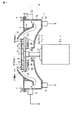
図1乃至図4はこの発明の第1の実施の形態を示し、図1に示す処理装置はカップ体1を備えている。このカップ体1は下カップ1aと上カップ1bを有する。この下カップ1aは上面が開放したお椀状に形成され、その底部中心部には通孔2が形成されていて、上端縁には受けフランジ3が設けられている。
Embodiments of the present invention will be described below with reference to the drawings.
1 to 4 show a first embodiment of the present invention, and the processing apparatus shown in FIG. The cup body 1 has a lower cup 1a and an
上記上カップ1bは外周面が凸曲面のリング状に形成されていて、その外周面には取付け部材4を介して連結フランジ5が設けられている。そして、上カップ1bは連結フランジ5を上記受けフランジ3にパッキング6を介して重合させ、それらが複数のねじ7によって連結固定されている。
The
上記下カップ1aに形成された通孔2からカップ体1の内部には駆動源であるモータ8の駆動軸9が挿通されている。この駆動軸9の上端には回転テーブル11が取付けられている。それによって、回転テーブル11は上記モータ8によって回転駆動されるようになっている。なお、上記モータ8は図示しない制御装置によって駆動が制御される。それによって、回転テーブル11の回転速度を変えることができるようになっている。
A
上記回転テーブル11には前工程である洗浄工程で洗浄された、たとえば液晶表示装置に用いられる矩形状の基板13が供給されて後述するように保持される。したがって、上記回転テーブル11とともに上記基板13が回転駆動されると、この基板13に付着した洗浄液が遠心力によって除去されるようになっている。つまり、基板13は乾燥処理される。
For example, a
上記下カップ1aの底壁には複数の排水口体14が設けられ、この排水口体14は図示しない排液ポンプに接続されている。さらに、下カップ1aの周壁には複数の排気口体15が接続されている。これら排気口体15は図示しない排気ポンプに接続されている。
A plurality of
上記排水口体14は基板13から飛散して下カップ1aに溜まる洗浄液を排出する。上記排気口体15に発生する吸引力はカップ体1内に図1に矢印で示すように、回転テーブル11に保持された基板13の上面から上記排気口体15に向かう円滑な空気流を発生させる。
The
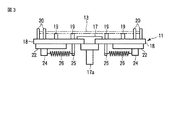
図2と図3に示すように、上記回転テーブル11は円盤状の基部17を有する。この基部17の下面には軸部17aが設けられ、この軸部17aが上記モータ8の駆動軸9に形成された図示しない嵌合孔に連結されている。
As shown in FIGS. 2 and 3, the rotary table 11 has a disk-shaped
上記基部17からは基端部を連結し先端部がT字状に形成された4本のアーム体18が放射状に延出されている。各アーム体18の上面の中途部にはそれぞれ2本の支持部材としての支持ピン19が長手方向に所定間隔で設けられ、先端部には2本の係合部材としての係合ピン20が回転テーブル11の回転方向に所定間隔で離間して設けられている。
From the
上記回転テーブル11に供給される上記基板13は、対角線方向に沿う下面中途部が上記支持ピン19によって支持され、4つの角部の外面に各一対の係合ピン20が係合する。それによって、上記回転テーブル11がモータ8によって回転駆動されると、この回転テーブル11と一体的に回転するようになっている。
The
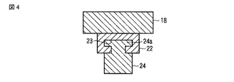
上記回転テーブル11の各アーム体18の下面の先端部にはリニアガイド22がアーム体18の長手方向、つまり回転テーブル11の径方向に沿って設けられている。図4に示すように、このリニアガイド22には断面形状がT字状のガイド溝23が長手方向に沿って形成され、このガイド溝23にはバランスウエイト24の上面に設けられた上記ガイド溝23に対応する形状の係合部24aが移動可能に係合している。
A
図3に示すように、上記アーム体18の下面の、上記リニアガイド22よりも回転テーブル11の径方向中心寄りには連結部材25が設けられている。この連結部材25と上記バランスウエイト24の間には弾性保持手段としてのばね26が張設されている。このばね26は上記バランスウエイト24を回転テーブル11の径方向に対して弾性的に保持している。
As shown in FIG. 3, a connecting
つまり、上記回転テーブル11が回転駆動されて上記バランスウエイト24に遠心力が発生すると、その遠心力によって上記バランスウエイト24は上記ばね26を弾性的に引き伸ばしながらリニアガイド22に沿って回転テーブル11の径方向外方へ移動する。
That is, when the rotary table 11 is rotationally driven and a centrifugal force is generated in the
上記バランスウエイト24が回転テーブル11の径方向外方へ移動する距離は、回転テーブル11の回転数が増大するにつれて大きくなる。バランスウエイト24の移動距離が大きくなれば、その移動距離に応じてバランスウエイト24に発生する遠心力も大きくなる。それによって、バランスウエイト24が回転テーブル11のアーム体18の先端部を上方へ撓ませる力が増大することになる。
The distance that the
上記バランスウエイト24は、少なくとも上記アーム体18の先端部、つまり係合ピン20と対応する位置まで上記リニアガイド22に沿って移動できるようになっている。さらに、バランスウエイト24の重量は一対の係合ピン20と同等以上に設定されている。
The
上記ばね26は、上記回転テーブル11を所定以上の回転数で回転させたとき、その回転によって生じる遠心力で上記バランスウエイト24が回転テーブル11の回転中心から径方向の所定の位置まで移動する。
When the rotary table 11 is rotated at a predetermined rotation speed or more, the
そして、上記バランスウエイト24が径方向の所定の位置まで移動したとき、このバランスウエイト24に生じる遠心力が上記一対の係合ピン20に生じる遠心力と同等以上になるよう、上記バランスウエイト24の重量が設定されている。
Then, when the
つまり、回転テーブル11が所定の回転数以上で回転駆動されて、一対の係合ピン20に生じる遠心力でアーム体18の先端部を下方へ撓ませる力が発生したとき、上記バランスウエイト24には一対の係合ピン20に生じる遠心力よりも大きな遠心力が発生するよう、その重量に応じて径方向外方の所定の位置まで移動する。
That is, when the rotary table 11 is rotationally driven at a predetermined rotational speed or more and a force that causes the distal end portion of the
それによって、回転テーブル11が所定以上の回転数で回転駆動されたとき、アーム体18の先端部は下方へ撓むことなく、上方へ撓むことになるから、係合ピン20が基板13から外れるのを確実に防止することができる。
Accordingly, when the rotary table 11 is driven to rotate at a predetermined number of rotations or more, the distal end portion of the
なお、回転テーブル11が所定以上の回転数で回転駆動されたとき、アーム体18の先端部が下方及び上方の両方に撓むことがないよう、バランスウエイト24のばね26を引き伸ばしての移動距離、つまりばね26の強さやバランスウエイト24の重量を設定するようにしてもよい。
When the rotary table 11 is driven to rotate at a predetermined number of rotations or more, the distance traveled by extending the
このような構成の処理装置によれば、たとえば前工程で洗浄処理された基板13を乾燥処理する場合、回転テーブル11に基板13を保持して、この回転テーブル11を高速回転させる。それによって、基板13に付着残留する洗浄液は基板13の回転によって生じる遠心力で飛散除去されるから、基板13が乾燥処理されることになる。
According to the processing apparatus having such a configuration, for example, when the
回転テーブル11を高速回転させると、回転テーブル11の各アーム体18の先端部の上面に設けられた一対の係合ピン20に遠心力が発生し、その遠心力がアーム体18を下方へ撓ませる力となる。
When the rotary table 11 is rotated at a high speed, a centrifugal force is generated at the pair of engaging
一方、各アーム体18の先端部の下面にはバランスウエイト24がリニアガイド22に沿って移動可能に設けられている。バランスウエイト24はばね26によって弾性的に保持され、回転テーブル11の回転に応じて生じる遠心力で上記ばね26を引き伸ばして回転テーブル11の径方向外方へ移動する。
On the other hand, a
すなわち、バランスウエイト24は回転テーブル11を高速回転させると、その回転速度に応じて径方向外方へ移動する。バランスウエイト24が径方向外方へ移動すれば、その移動距離の二乗に比例してバランスウエイト24に発生する遠心力が増大する。
That is, when the rotary table 11 is rotated at a high speed, the
そのため、回転テーブル11を高速回転させることで、その回転速度に応じて係合ピン20に発生する遠心力が増大しても、バランスウエイト24に発生する遠心力は回転速度に応じて増大するだけでなく、回転テーブル11の回転中心からの半径距離が大きくなることによっても増大する。つまり、係合ピン20に発生する遠心力よりもバランスウエイト24に発生する遠心力の方が大きく増大する。
Therefore, by rotating the rotary table 11 at a high speed, even if the centrifugal force generated in the
それによって、アーム体18先端部が係合ピン20の遠心力によって受ける下方へ撓まされる力よりも、バランスウエイト24の遠心力によって受ける上方へ撓まされる力の方が大きく増大することになるから、上記アーム体18が下方へ撓んで係合ピン20が基板13から外れるのを確実に防止することができる。
Thereby, the force deflected upward by the centrifugal force of the
図5乃至図8はそれぞれこの発明の他の実施の形態を示す。
図5はこの発明の第2の実施の形態を示し、この実施の形態はアーム体18の先端に連結部材25を設け、この連結部材25とバランスウエイト24との間に、回転テーブル11の回転によってバランスウエイト24に生じる遠心力でこのバランスウエイト24が回転テーブル11の径方向外方へ移動したときに圧縮されるばね26aを設けるようにした。
5 to 8 show other embodiments of the present invention.
FIG. 5 shows a second embodiment of the present invention. In this embodiment, a connecting
このような構成によれば、回転テーブル11の回転によってバランスウエイト24に遠心力が発生すれば、バランスウエイト24がばね26aを圧縮させながら径方向外方へ移動する。それによって、第1の実施の形態と同様、回転テーブル11の回転によって係合ピン20に発生する遠心力の増大よりもバランスウエイト24に発生する遠心力の増大の方が大きくなるから、回転テーブル11のアーム体18が下方へ撓むのを防止することができる。
According to such a configuration, when centrifugal force is generated in the
図6はこの発明の第3の実施の形態を示し、この実施の形態はアーム体18の下面にリニアガイド22を設けず、アーム体18にバランスウエイト24の係合部24aが移動可能に係合する係合溝27を形成するようにした。
FIG. 6 shows a third embodiment of the present invention. In this embodiment, the
この第3の実施の形態において、バランスウエイト24を係合溝27に弾性的に保持するには、第1の実施の形態のようにバランスウエイト24が径方向外方へ移動したときに引張られるばね26を設けてもよく、或いは第2の実施の形態のように圧縮されるばね26aを設けてもよい。
In the third embodiment, in order to elastically hold the
図7はこの発明の第4の実施の形態を示し、この実施の形態はバランスウエイト24にアーム体18に移動可能に係合する断面形状がほぼU字状の係合部24bを設けるようにしたもので、この場合も回転テーブル11の回転によってバランスウエイト24を弾性的に保持するばねはバランスウエイト24が径方向外方へ移動したときに第1の実施の形態に示されるように引張られるばね26或いは第2の実施の形態のように圧縮されるばね26aのいずれを用いてもよい。
FIG. 7 shows a fourth embodiment of the present invention. In this embodiment, the
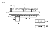
図8と図9はこの発明の第5の実施の形態で、この実施の形態はアーム体18の下面にリニアガイド22を設け、このリニアガイド22のガイド溝23にバランスウエイト24の係合部24aを移動可能に係合させるという点では第1の実施の形態と同じであるが、リニアガイド22のガイド溝23或いはバランスウエイト24の係合部24aのどちらか一方、この実施の形態ではリニアガイド22のガイド溝23にコイル30を設けて電磁石で形成し、バランスウエイト24の少なくとも上記コイル30に対向する係合部24aを永久磁石によって形成する。それによって、上記コイル30と永久磁石とで駆動手段としてのリニアモータを構成する。
FIGS. 8 and 9 show a fifth embodiment of the present invention. In this embodiment, a
そして、図8に示すように、リニアガイド22に設けられたコイル30に給電用の電源28を接続し、この電源28による上記コイル30への給電を制御装置29によって制御する。つまり、回転テーブル11を高速回転させるときには電磁石を構成するコイル30に通電し、上記バランスウエイト24をリニアガイド22に沿って移動させ、回転テーブル11の径方向の所定の位置、つまり回転テーブル11の回転数の増加に応じて径方向の外方に位置決めする。
Then, as shown in FIG. 8, a
このような構成によれば、回転テーブル11の回転数に応じたバランスウエイト24の位置決めを正確に行なうことが可能となるから、回転テーブル11を高速回転させたときにアーム体18に発生する撓みを精度よく制御することが可能となる。
According to such a configuration, the
なお、電源28からリニアガイド22への給電は、図示しないが、たとえばモータ8の駆動軸9に導電リングを設け、この導電リングに接触するブラシを介して行うようにすればよい。
Although power supply from the
上記バランスウエイトを回転テーブルの回転数の増加に応じて径方向外方へ移動させる手段としては上記各実施の形態に限られず、たとえばガスプリングを用いてもよい。つまり、ガススプリングは回転テーブルが高速回転してバランスウエイトに遠心力が生じると、その遠心力でシリンダ内に充填されたガスが圧縮される構成となっている。 The means for moving the balance weight outward in the radial direction in accordance with the increase in the number of rotations of the rotary table is not limited to the above-described embodiments, and, for example, a gas spring may be used. That is, the gas spring is configured such that when the rotary table rotates at a high speed and a centrifugal force is generated in the balance weight, the gas filled in the cylinder is compressed by the centrifugal force.
したがって、上記ガススプリングのロッドに上記バランスウエイトを連結すれば、回転テーブルの回転数が増大するにつれてこのバランスウエイトを回転テーブルの径方向外方へ移動させることが可能となる。 Therefore, if the balance weight is connected to the rod of the gas spring, the balance weight can be moved outward in the radial direction of the rotary table as the rotational speed of the rotary table increases.
また、バランスウエイトを径方向に移動させることにより、回転テーブルの加減速時に発生する慣性力が低下し、駆動源の回転トルクや制動力を低減させることができる。それにより、駆動源の小型化や加減速時間の短縮、或いは回転テーブルの剛性を低くして軽量化を図るなどのことができる。 Further, by moving the balance weight in the radial direction, the inertial force generated during acceleration / deceleration of the rotary table is reduced, and the rotational torque and braking force of the drive source can be reduced. As a result, it is possible to reduce the size of the drive source, shorten the acceleration / deceleration time, or reduce the rigidity of the rotary table to reduce the weight.
上記各実施の形態では回転テーブルが基部に複数のアーム体が放射状に設けられた形状である場合について説明したが、回転テーブルは円盤状や矩形状などであってもよく、要は基板の下面を支持する支持ピン及び角部外面に係合する係合ピンを有する構造であれば、この発明を適用することが可能とである。 In each of the above-described embodiments, the case where the rotary table has a shape in which a plurality of arm bodies are provided radially at the base has been described. However, the rotary table may be a disk shape, a rectangular shape, or the like. The present invention can be applied to any structure having a support pin that supports the engagement pin and an engagement pin that engages with the outer surface of the corner.
11…回転テーブル、8…モータ(駆動源)、13…基板、18…アーム体、19…支持ピン(支持部材)、20…係合ピン(係合部材)、22…リニアガイド、23…ガイド溝、24…バランスウエイト、26,26a…ばね(弾性保持手段)。
DESCRIPTION OF
Claims (5)
回転テーブルと、
この回転テーブルを回転駆動する駆動源と、
上記回転テーブルの上面に設けられた上記基板の下面を支持する支持部材及び上記基板の外面に係合する係合部材と、
上記回転テーブルの下面に径方向に沿って位置決め可能に設けられ上記回転テーブルの回転速度が増大するにつれて径方向の外方に位置決めされて上記係合部材の遠心力によって生じる上記回転テーブルの周辺部を下方へ撓ませる力を打ち消す力を発生するバランスウエイトと
を具備したことを特徴とする基板の処理装置。 A processing apparatus for processing while rotating a substrate,
A rotating table,
A drive source for rotationally driving the rotary table;
A support member that supports the lower surface of the substrate provided on the upper surface of the turntable, and an engagement member that engages with the outer surface of the substrate;
A peripheral portion of the rotary table that is provided on the lower surface of the rotary table so as to be positioned along the radial direction and is positioned outward in the radial direction as the rotational speed of the rotary table increases and is generated by the centrifugal force of the engaging member. A substrate weight processing apparatus comprising: a balance weight that generates a force that counteracts a force that deflects the substrate downward.
上記バランスウエイトを上記回転テーブルの径方向に沿って弾性的に移動可能に保持し上記回転テーブルが回転して上記バランスウエイトに遠心力が生じたときにその遠心力によって弾性変形して上記バランスウエイトを上記リニアガイドに沿って上記回転テーブルの径方向の外方へ移動させる弾性保持手段と
を具備したことを特徴とする請求項1記載の基板の処理装置。 A linear guide provided on the lower surface of the rotary table and supporting the balance weight movably along the radial direction;
The balance weight is held elastically movable along the radial direction of the rotary table, and when the rotary table rotates and a centrifugal force is generated in the balance weight, the balance weight is elastically deformed by the centrifugal force. The substrate processing apparatus according to claim 1, further comprising: an elastic holding means that moves the rotary table outward in the radial direction of the rotary table along the linear guide.
上記回転テーブルの回転速度に応じて上記バランスウエイトを上記リニアガイドに沿って駆動して上記回転テーブルの径方向に沿う所定の位置に位置決めする駆動手段と
を具備したことを特徴とする請求項1記載の基板の処理装置。 A linear guide provided along the radial direction on the lower surface of the rotary table and supported by the balance weight so as to be movable;
2. A driving means for driving the balance weight along the linear guide in accordance with the rotation speed of the rotary table and positioning the balance weight at a predetermined position along the radial direction of the rotary table. The substrate processing apparatus as described.
各アーム体の上面には上記支持部材と上記係合部材が設けられ、上記アーム体の下面には上記バランスウエイトが上記回転テーブルの回転速度に応じて径方向の所定の位置に位置決めされるよう設けられていることを特徴とする請求項1記載の基板の処理装置。 The rotary table includes a base portion connected to the drive source, and a plurality of arm bodies extending radially by connecting a base end to the base portion,
The support member and the engagement member are provided on the upper surface of each arm body, and the balance weight is positioned on the lower surface of the arm body at a predetermined radial position according to the rotation speed of the rotary table. The substrate processing apparatus according to claim 1, wherein the substrate processing apparatus is provided.
基板の下面を支持する支持部材及び外面に係合する係合部材が設けられた回転テーブルに上記基板を保持して回転させる工程と、
上記回転テーブルの下面に設けられたバランスウエイトを回転テーブルの回転速度の増加に応じて径方向の外方に移動させ、上記回転テーブルの回転によって上記係合部材に発生する上記回転テーブルの周辺部を下方へ撓ませる遠心力を打ち消す遠心力を上記バランスウエイトによって生じさせる工程と
を具備したことを特徴とする基板の処理方法。 A processing method for processing while rotating a substrate,
Holding and rotating the substrate on a turntable provided with a support member that supports the lower surface of the substrate and an engagement member that engages with the outer surface; and
The balance weight provided on the lower surface of the turntable is moved radially outward in response to an increase in the rotation speed of the turntable, and the periphery of the turntable generated in the engaging member by the rotation of the turntable And a step of generating, by the balance weight, a centrifugal force that cancels the centrifugal force that bends the substrate downward.
Priority Applications (1)
| Application Number | Priority Date | Filing Date | Title |
|---|---|---|---|
| JP2008164876A JP5274911B2 (en) | 2008-06-24 | 2008-06-24 | Substrate processing equipment |
Applications Claiming Priority (1)
| Application Number | Priority Date | Filing Date | Title |
|---|---|---|---|
| JP2008164876A JP5274911B2 (en) | 2008-06-24 | 2008-06-24 | Substrate processing equipment |
Publications (2)
| Publication Number | Publication Date |
|---|---|
| JP2010010221A true JP2010010221A (en) | 2010-01-14 |
| JP5274911B2 JP5274911B2 (en) | 2013-08-28 |
Family
ID=41590393
Family Applications (1)
| Application Number | Title | Priority Date | Filing Date |
|---|---|---|---|
| JP2008164876A Expired - Fee Related JP5274911B2 (en) | 2008-06-24 | 2008-06-24 | Substrate processing equipment |
Country Status (1)
| Country | Link |
|---|---|
| JP (1) | JP5274911B2 (en) |
Cited By (2)
| Publication number | Priority date | Publication date | Assignee | Title |
|---|---|---|---|---|
| CN108091598A (en) * | 2016-11-21 | 2018-05-29 | 东京毅力科创株式会社 | Substrate board treatment |
| CN110323159A (en) * | 2018-03-30 | 2019-10-11 | 芝浦机械电子株式会社 | Substrate board treatment |
Citations (3)
| Publication number | Priority date | Publication date | Assignee | Title |
|---|---|---|---|---|
| JPS63203943A (en) * | 1987-02-18 | 1988-08-23 | Ricoh Co Ltd | Rotation unevenness reduction device for rotating bodies |
| JPH06244165A (en) * | 1993-02-16 | 1994-09-02 | Hitachi Ltd | Rotation processing device |
| JP2001221291A (en) * | 2000-02-04 | 2001-08-17 | Nippon Densan Corp | Rotation balance correction device |
-
2008
- 2008-06-24 JP JP2008164876A patent/JP5274911B2/en not_active Expired - Fee Related
Patent Citations (3)
| Publication number | Priority date | Publication date | Assignee | Title |
|---|---|---|---|---|
| JPS63203943A (en) * | 1987-02-18 | 1988-08-23 | Ricoh Co Ltd | Rotation unevenness reduction device for rotating bodies |
| JPH06244165A (en) * | 1993-02-16 | 1994-09-02 | Hitachi Ltd | Rotation processing device |
| JP2001221291A (en) * | 2000-02-04 | 2001-08-17 | Nippon Densan Corp | Rotation balance correction device |
Cited By (4)
| Publication number | Priority date | Publication date | Assignee | Title |
|---|---|---|---|---|
| CN108091598A (en) * | 2016-11-21 | 2018-05-29 | 东京毅力科创株式会社 | Substrate board treatment |
| CN108091598B (en) * | 2016-11-21 | 2023-03-28 | 东京毅力科创株式会社 | Substrate processing apparatus |
| CN110323159A (en) * | 2018-03-30 | 2019-10-11 | 芝浦机械电子株式会社 | Substrate board treatment |
| CN110323159B (en) * | 2018-03-30 | 2023-02-03 | 芝浦机械电子株式会社 | Substrate processing apparatus |
Also Published As
| Publication number | Publication date |
|---|---|
| JP5274911B2 (en) | 2013-08-28 |
Similar Documents
| Publication | Publication Date | Title |
|---|---|---|
| CN100517633C (en) | Spin head and substrate treating method using the same | |
| US10204818B2 (en) | Device for holding and rotating plate shaped article | |
| KR20180018341A (en) | Bonding apparatus and bonding system | |
| JPH06291030A (en) | Substrate rotating and holding device for rotary substrate treatment apparatus | |
| CN104701233A (en) | Holding device for disc-like object | |
| TW201631690A (en) | Substrate transfer device | |
| CN103762196B (en) | The clamping device of pan and the rotation platform of pan | |
| JP5274911B2 (en) | Substrate processing equipment | |
| JP4920643B2 (en) | Liquid processing apparatus and liquid processing method | |
| JP7160872B2 (en) | SUBSTRATE PROCESSING APPARATUS AND DRIVING METHOD THEREOF | |
| EP1233667B1 (en) | Electronic component mounting apparatus | |
| CN108231644B (en) | Substrate lifter for mask aligner | |
| CN118943067B (en) | Wafer positioning device for glue coating and developing machine | |
| JP2009206288A (en) | Thin substrate rotation processing equipment | |
| JP2004079637A (en) | Device for holding plate member, method for holding, and spin processing device | |
| JP3343012B2 (en) | Rotary substrate processing equipment | |
| JPH10135312A (en) | Substrate rotation holding apparatus and rotary substrate treating apparatus | |
| CN111015502A (en) | Positioning device | |
| KR100857233B1 (en) | Substrate spin device | |
| JPH1140655A (en) | Substrate rotation holding device and rotary substrate processing device | |
| JP2000223395A (en) | Device for spin-coating semiconductor products and method for spin-coating semiconductor products | |
| JPH11252875A (en) | Armature coil winding device and method | |
| JP2001185522A (en) | Processing equipment for rectangular substrates | |
| KR100855737B1 (en) | Wafer spin chuck | |
| JP2008141010A (en) | Substrate treatment apparatus |
Legal Events
| Date | Code | Title | Description |
|---|---|---|---|
| A621 | Written request for application examination |
Free format text: JAPANESE INTERMEDIATE CODE: A621 Effective date: 20110623 |
|
| A977 | Report on retrieval |
Free format text: JAPANESE INTERMEDIATE CODE: A971007 Effective date: 20121015 |
|
| A131 | Notification of reasons for refusal |
Free format text: JAPANESE INTERMEDIATE CODE: A131 Effective date: 20121023 |
|
| A521 | Written amendment |
Free format text: JAPANESE INTERMEDIATE CODE: A523 Effective date: 20121219 |
|
| TRDD | Decision of grant or rejection written | ||
| A01 | Written decision to grant a patent or to grant a registration (utility model) |
Free format text: JAPANESE INTERMEDIATE CODE: A01 Effective date: 20130507 |
|
| A61 | First payment of annual fees (during grant procedure) |
Free format text: JAPANESE INTERMEDIATE CODE: A61 Effective date: 20130515 |
|
| R150 | Certificate of patent or registration of utility model |
Free format text: JAPANESE INTERMEDIATE CODE: R150 Ref document number: 5274911 Country of ref document: JP Free format text: JAPANESE INTERMEDIATE CODE: R150 |
|
| LAPS | Cancellation because of no payment of annual fees |