JP2010064355A - Printing method and printing device using thermal head - Google Patents
Printing method and printing device using thermal head Download PDFInfo
- Publication number
- JP2010064355A JP2010064355A JP2008232634A JP2008232634A JP2010064355A JP 2010064355 A JP2010064355 A JP 2010064355A JP 2008232634 A JP2008232634 A JP 2008232634A JP 2008232634 A JP2008232634 A JP 2008232634A JP 2010064355 A JP2010064355 A JP 2010064355A
- Authority
- JP
- Japan
- Prior art keywords
- thermal head
- recording medium
- dots
- dot
- voltage
- Prior art date
- Legal status (The legal status is an assumption and is not a legal conclusion. Google has not performed a legal analysis and makes no representation as to the accuracy of the status listed.)
- Pending
Links
Images


Landscapes
- Electronic Switches (AREA)
Abstract
【課題】サーマルヘッドを用いて、インクリボン等の転写箔を用いず、樹脂等からなる記録媒体に直接印字パターンを形成する印字方法、また、サーマルヘッドを用いて、ホットスタンピング法と同等の印字パターンを形成する印字方法を提供する。
【解決手段】サーマルヘッド11の発熱体の発熱により、保護シート22を介して、記録媒体(装飾用リボン21)の表面状態を変化させ、記録媒体からなる発熱体の発熱に対応した前記各ドットを形成する。また、印字パターンの輪郭を構成するドットにはより多くの熱量を付与して輪郭線が明瞭な印字パターンを形成し、更に、隣接するドット同士が連結した印字パターンを形成する。
【選択図】図1A printing method for directly forming a printing pattern on a recording medium made of resin without using a transfer foil such as an ink ribbon using a thermal head, and a printing equivalent to a hot stamping method using a thermal head A printing method for forming a pattern is provided.
Each of the dots corresponding to the heat generation of the heating element made of the recording medium is changed by changing the surface state of the recording medium (decorative ribbon 21) through the protective sheet 22 by the heat generation of the heating element of the thermal head. Form. In addition, a larger amount of heat is applied to the dots constituting the outline of the print pattern to form a print pattern with a clear outline, and further, a print pattern in which adjacent dots are connected is formed.
[Selection] Figure 1
Description
本発明は、サーマルヘッドを用いた印字方法及び印字装置に関し、更に詳しくは、インクリボン等の転写箔を用いず、樹脂等からなる記録媒体に直接印字パターンを形成するサーマルヘッドを用いた印字方法及び印字装置に関する。また、他の本発明は、そのような記録媒体への直接印字パターン形成、金属転写箔を用いての印字パターン形成等を行う場合に好適なサーマルヘッドを用いた印字方法及び印字装置に関する。 The present invention relates to a printing method and a printing apparatus using a thermal head, and more specifically, a printing method using a thermal head that directly forms a printing pattern on a recording medium made of a resin without using a transfer foil such as an ink ribbon. And a printing apparatus. Another aspect of the present invention relates to a printing method and a printing apparatus using a thermal head suitable for performing such a direct printing pattern formation on a recording medium and a printing pattern formation using a metal transfer foil.
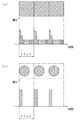
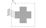
従来より、サーマルヘッドをインクリボン等の転写箔に押付け、加熱する熱転写プリンタを使用して転写箔から転写層を転写し、印刷する方法が知られている(例えば、特許文献1参照)。この熱転写プリンタはパーソナルコンピュータ等から送られてくる信号に基づいて発熱体を備えたサーマルヘッドによってインクリボンに塗布されたインクを加熱し、用紙などに転写するものである。このような印刷方法では、通常、図9に示すように、印字される印字パターンPがそれぞれが独立した点として形成された多数のドットDの集合体として形成される。そして、そのような各ドットの形成は、図7(b)に示すように、サーマルヘッドの発熱体に、1ドットあたり1回の電圧印加を行うことにより簡単に成し得るものである。
ところが、上述のような印字方法で転写層に金属層を備える転写箔(以下、金属転写箔という)を転写して形成された印字パターンは、各ドットが点として形成され、それらの集合体として印字パターンが形成されているため、金属光沢に乏しく、見栄えも悪い。これは、各ドット間に隙間が生じている、又は、各ドット間において、転写層と記録媒体との密着性が悪く、皺等が生じているためである。また、点の集合により構成された印字パターンは、その輪郭も不明瞭である。
2. Description of the Related Art Conventionally, a method is known in which a thermal layer is pressed from a transfer foil such as an ink ribbon, and a transfer layer is transferred from the transfer foil using a thermal transfer printer that heats the print (see, for example, Patent Document 1). This thermal transfer printer heats ink applied to an ink ribbon by a thermal head equipped with a heating element based on a signal sent from a personal computer or the like, and transfers the ink onto a sheet or the like. In such a printing method, as shown in FIG. 9, the printed pattern P to be printed is usually formed as an aggregate of a large number of dots D formed as independent points. Then, as shown in FIG. 7B, such dot formation can be easily achieved by applying a voltage once per dot to the heating element of the thermal head.
However, in a printing pattern formed by transferring a transfer foil (hereinafter referred to as a metal transfer foil) provided with a metal layer to a transfer layer by the printing method as described above, each dot is formed as a dot, Since the printed pattern is formed, the metallic luster is poor and the appearance is poor. This is because there is a gap between the dots, or between the dots, the adhesion between the transfer layer and the recording medium is poor and wrinkles or the like are generated. Moreover, the outline of the print pattern constituted by the set of points is also unclear.
一方、金属転写箔を転写して印字パターンを形成する方法としては、箔押などのホットスタンピング法が知られている(特許文献1参照)。具体的には、転写箔はフィルム等からなる基材に顔料や蒸着させた金属等からなる転写層を積層して形成されている。このような転写箔に対しては、箔押では、所定の印刷パターンを有する転写金型を転写箔側から押し付け、熱圧着することにより被転写材に印刷パターンを転写させている。また、ホットスタンプ印刷では、熱転写用インクで形成した転写箔を用いて熱板または熱ロールにより被転写材に転写させている。即ち、ホットスタンピング法で形成される印字パターンは、転写された転写層は、上述のような点の集合体として形成されるものではなく、転写金型や版等により圧着された転写層が、その形状のまま転写されて形成されるものである。これにより、圧着された転写層からなる印字パターンは、その全面が金属光沢を有する美しい印字パターンとなる。 On the other hand, a hot stamping method such as foil stamping is known as a method for forming a print pattern by transferring a metal transfer foil (see Patent Document 1). Specifically, the transfer foil is formed by laminating a transfer layer made of pigment, vapor deposited metal, or the like on a base material made of a film or the like. For such a transfer foil, in the foil stamping, a transfer mold having a predetermined print pattern is pressed from the transfer foil side, and the print pattern is transferred to the transfer material by thermocompression bonding. In hot stamp printing, a transfer foil formed of thermal transfer ink is used to transfer to a transfer material using a hot plate or a hot roll. That is, the print pattern formed by the hot stamping method is not formed as an aggregate of the points as described above, but the transfer layer pressed by a transfer mold, a plate, or the like is used. It is transferred and formed as it is. As a result, the print pattern composed of the pressure-transferred transfer layer becomes a beautiful print pattern whose entire surface has a metallic luster.
ところが、このホットスタンピング法は、被転写材毎に所望の印刷パターンを有する転写金型や版を個別に作成しなければならないから、コストがかかり高価なものとなっていた。また、印刷装置自体が大型なものとなっていた。そして、印刷パターンを一部修正する場合には、転写金型や版を修正したり、新たに作成し直さなければならなかった。 However, this hot stamping method is costly and expensive because a transfer mold or plate having a desired printing pattern must be individually created for each transfer material. In addition, the printing apparatus itself is large. In order to partially correct the printing pattern, it is necessary to correct the transfer mold or plate or newly create it again.
本発明は、サーマルヘッドを用いた印字方法及び印字装置であって、インクリボン等の転写箔を用いず、樹脂等からなる記録媒体に直接印字パターンを形成する印字方法及び印字装置の提供を課題とするものである。また、他の本発明は、そのような記録媒体への直接印字パターン形成や金属転写箔を用いての印字パターン形成等を行う場合等に好適な、隣接する各ドット同士を結合させたホットスタンピング法と同等の印字パターンを形成でき、また、印字パターンの輪郭も明瞭に表すことができるサーマルヘッドを用いた印字方法及び印字装置の提供を課題とするものである。 The present invention provides a printing method and a printing apparatus using a thermal head, and provides a printing method and a printing apparatus that directly form a printing pattern on a recording medium made of a resin or the like without using a transfer foil such as an ink ribbon. It is what. Another embodiment of the present invention is a hot stamping method in which adjacent dots are connected to each other, which is suitable for direct print pattern formation on such a recording medium or print pattern formation using a metal transfer foil. It is an object of the present invention to provide a printing method and a printing apparatus using a thermal head that can form a printing pattern equivalent to the method and can clearly express the outline of the printing pattern.
本発明は、以下の通りである。
1.直線状に配列された複数の発熱体を有するサーマルヘッドにより記録媒体を押圧した状態で、電圧を印加することにより前記各発熱体を選択的に発熱させると共に前記サーマルヘッドと前記記録媒体とを相対的に移動させ、前記各発熱体の発熱にそれぞれ対応したドットを前記記録媒体に形成し、該各ドットから構成される印字パターンを形成する印字方法であって、
前記発熱体の発熱により前記記録媒体の表面状態を変化させ、該記録媒体からなる前記ドットを形成することを特徴とするサーマルヘッドを用いた印字方法。
2.前記ドットは、前記サーマルヘッド及び前記記録媒体の間に設けられ、且つ、前記サーマルヘッドに対して相対的に移動する保護シートを介して形成される上記1.記載のサーマルヘッドを用いた印字方法。
3.前記記録媒体の材質は、合成樹脂、ゴム又は皮革である上記1.又は上記2.記載のサーマルヘッドを用いた印字方法。
4.直線状に配列された複数の発熱体を有するサーマルヘッドにより記録媒体を押圧した状態で、電圧を印加することにより前記各発熱体を選択的に発熱させると共に前記サーマルヘッドと前記記録媒体とを相対的に移動させ、前記各発熱体の発熱にそれぞれ対応したドットを前記記録媒体に形成し、該各ドットから構成される印字パターンを形成する印字方法であって、
前記各ドットは、それぞれ前記相対移動の1ドットあたりの移動時間と等しい時間連続して前記電圧が印加されて形成されることを特徴とするサーマルヘッドを用いた印字方法。
5.前記各ドットは、それぞれ前記電圧の大きさを段階的に小さくして形成される上記4.記載のサーマルヘッドを用いた印字方法。
6.直線状に配列された複数の発熱体を有するサーマルヘッドにより記録媒体を押圧した状態で、電圧を印加することにより前記各発熱体を選択的に発熱させると共に前記サーマルヘッドと前記記録媒体とを相対的に移動させ、前記各発熱体の発熱にそれぞれ対応したドットを前記記録媒体に形成し、該各ドットから構成される印字パターンを形成する印字方法であって、
前記印字パターンの形状の情報である印字データを取得する印字データ取得工程と、
前記印字データに基づいて、前記記録媒体に形成されるドットの配列情報であるドット配列データを生成するドット配列データ生成工程と、
前記ドット配列データに基づいて、前記各ドットの周囲に形成されるドットの有無を参照して前記各発熱体に印加する電圧の大きさ及び/又は印加時間をそれぞれ設定し、印加電圧データを生成する印加電圧データ生成工程と、
前記ドット配列データ及び前記印加電圧データに基づいて、前記各発熱体を発熱させる信号を出力する出力工程と、を備えることを特徴とするサーマルヘッドを用いた印字方法。
7.前記各ドットは、それぞれ前記相対移動の1ドットあたりの移動時間と等しい時間連続して前記電圧が印加されて形成される上記6.記載のサーマルヘッドを用いた印字方法。
8.前記各ドットは、それぞれ前記電圧の大きさを段階的に小さくして形成される上記7.記載のサーマルヘッドを用いた印字方法。
9.前記参照に用いられるドットの有無は、少なくとも前記各ドットの前記相対移動の前後方向及び直交方向の四方それぞれ1〜7つのドットの有無である上記6.乃至上記8.のいずれかに記載のサーマルヘッドを用いた印字方法。
10.前記参照に用いられるドットの有無は、少なくとも前記各ドットの前記相対移動方向の前方3つ、後方2つ、及び該相対移動方向に直交する方向の両方各2つの計9つのドットの有無である上記6.乃至上記8.のいずれかに記載のサーマルヘッドを用いた印字方法。
11.前記ドットは、前記発熱体の発熱により、転写層に金属層を備える転写箔から転写される転写層からなるドットである上記4.乃至上記10.のいずれかに記載のサーマルヘッドを用いた印字方法。
12.前記ドットは、前記発熱体の発熱により前記記録媒体の表面状態を変化させて形成される該記録媒体からなるドットである上記4.乃至上記10.のいずれかに記載のサーマルヘッドを用いた印字方法。
13.前記ドットは、前記サーマルヘッド及び前記記録媒体の間に設けられ、且つ、前記サーマルヘッドに対して相対的に移動する保護シートを介して形成される上記12.記載のサーマルヘッドを用いた印字方法。
14.前記記録媒体の材質は、合成樹脂、ゴム又は皮革である上記4.乃至上記13.のいずれかに記載のサーマルヘッドを用いた印字方法。
15.前記サーマルヘッドは予熱されている上記1.乃至上記14.のいずれかに記載のサーマルヘッドを用いた印字方法。
16.直線状に配列された複数の発熱体を有するサーマルヘッドにより記録媒体を押圧した状態で、電圧を印加することにより前記各発熱体を選択的に発熱させると共に前記サーマルヘッドと前記記録媒体とを相対的に移動させ、前記各発熱体の発熱にそれぞれ対応したドットを前記記録媒体に形成し、該各ドットから構成される印字パターンを形成する印字方法であって、
前記印字パターンの形状の情報である印字データを取得する印字データ取得工程と、
前記印字データに基づいて、前記記録媒体に形成されるドットの配列情報であるドット配列データを生成するドット配列データ生成工程と、
前記ドット配列データに基づいて、前記各ドットの周囲に形成されるドットの有無を参照して前記各発熱体に印加する電圧の大きさを設定し、印加電圧データを生成する印加電圧データ生成工程と、
前記ドット配列データ及び前記印加電圧データに基づいて、前記各発熱体を発熱させる信号を出力する出力工程と、を備え、
前記各ドットは、それぞれ前記相対移動の1ドットあたりの移動時間と等しい時間連続して前記電圧が印加されて形成されると共に、前記電圧の大きさを段階的に小さくして形成され、
前記参照に用いられるドットの有無は、少なくとも前記各ドットの前記相対移動方向の前方3つ、後方2つ、及び該相対移動方向に直交する方向の両方各2つの計9つのドットの有無であり、
前記ドットは、前記発熱体の発熱により前記記録媒体の表面状態を変化させて形成される該記録媒体からなるドットであり、
前記ドットは、前記サーマルヘッド及び前記記録媒体の間に設けられ且つ前記サーマルヘッドに対して相対的に移動する保護シートを介して形成され、
前記記録媒体は、樹脂繊維を織ってなる装飾用リボンであることを特徴とするサーマルヘッドを用いた印字方法。
17.前記サーマルヘッドは予熱されている上記16.記載のサーマルヘッドを用いた印字方法。
18.直線状に配列された複数の発熱体を有するサーマルヘッドと、
前記サーマルヘッドと記録媒体とを相対的に移動させる移動手段と、を備え、
前記サーマルヘッドにより前記記録媒体を押圧した状態で、電圧を印加することにより前記各発熱体を選択的に発熱させると共に前記移動手段により該サーマルヘッドと該記録媒体とを相対的に移動させ、該各発熱体の発熱にそれぞれ対応したドットを該記録媒体に形成し、該各ドットから構成される印字パターンを形成する印字装置であって、
前記発熱体の発熱により前記記録媒体の表面状態を変化させ、該記録媒体からなる前記ドットを形成することを特徴とする印字装置。
19.前記ドットは、前記サーマルヘッド及び前記記録媒体の間に設けられ、且つ、前記サーマルヘッドに対して相対的に移動する保護シートを介して形成される上記18.記載の印字装置。
20.前記記録媒体の材質は、合成樹脂、ゴム又は皮革である上記18.又は上記19.記載の印字装置。
21.直線状に配列された複数の発熱体を有するサーマルヘッドと、
前記サーマルヘッドと記録媒体とを相対的に移動させる移動手段と、を備え、
前記サーマルヘッドにより前記記録媒体を押圧した状態で、電圧を印加することにより前記各発熱体を選択的に発熱させると共に前記移動手段により該サーマルヘッドと該記録媒体とを相対的に移動させ、該各発熱体の発熱にそれぞれ対応したドットを該記録媒体に形成し、該各ドットから構成される印字パターンを形成する印字装置であって、
前記各発熱体の選択的な発熱は、1ドットあたりの電圧印加時間が前記相対移動の1ドットあたりの移動時間と等しい電圧印加による発熱であることを特徴とする印字装置。
22.前記各発熱体の選択的な発熱は、前記電圧の大きさが段階的に小さくなる電圧印加による発熱である上記21.記載の印字装置。
23.直線状に配列された複数の発熱体を有するサーマルヘッドと、
前記サーマルヘッドと記録媒体とを相対的に移動させる移動手段と、を備え、
前記サーマルヘッドにより前記記録媒体を押圧した状態で、電圧を印加することにより前記各発熱体を選択的に発熱させると共に前記移動手段により該サーマルヘッドと該記録媒体とを相対的に移動させ、該各発熱体の発熱にそれぞれ対応したドットを該記録媒体に形成し、該各ドットから構成される印字パターンを形成する印字装置であって、
前記印字パターンの形状の情報である印字データを取得する印字データ取得部と、
前記印字データに基づいて、前記記録媒体に形成されるドットの配列情報であるドット配列データを生成するドット配列データ生成部と、
前記ドット配列データに基づいて、前記各ドットの周囲に形成されるドットの有無を参照して前記各発熱体に印加する電圧の大きさ及び/又は印加時間をそれぞれ設定し、印加電圧データを生成する印加電圧データ生成部と、
前記ドット配列データ及び前記印加電圧データに基づいて、前記各発熱体を発熱させる信号を出力する出力部と、を備えることを特徴とする印字装置。
24.前記各発熱体の選択的な発熱は、1ドットあたりの電圧印加時間が前記相対移動の1ドットあたりの移動時間と等しい電圧印加による発熱である上記23.記載の印字装置。
25.前記各発熱体の選択的な発熱は、前記電圧の大きさが段階的に小さくなる電圧印加による発熱である上記24.記載の印字装置。
26.前記印加電圧データ生成部は、少なくとも前記各ドットの前記相対移動の前後方向及び直交方向の四方それぞれ1〜7つのドットの有無を参照して前記各発熱体に印加する電圧の大きさ及び/又は印加時間をそれぞれ設定する上記23.乃至25記載の印字装置。
27.前記印加電圧データ生成部は、少なくとも前記各ドットの前記相対移動方向の前方3つ、後方2つ、及び該相対移動方向に直交する方向の両方各2つの計9つのドットの有無を参照して前記各発熱体に印加する電圧の大きさ及び/又は印加時間をそれぞれ設定する上記23.乃至25記載の印字装置。
28.前記ドットは、前記発熱体の発熱に対応して転写層に金属層を備える転写箔から転写される転写層からなるドットである上記21.乃至上記27.のいずれかに記載の印字装置。
29.前記各ドットは、前記発熱体の発熱に対応して前記記録媒体の表面状態が変化されて形成されるドットである上記21.乃至上記27.のいずれかに記載の印字装置。
30.前記ドットは、前記サーマルヘッド及び前記記録媒体の間に設けられ、且つ、前記サーマルヘッドに対して相対的に移動する保護シートを介して形成される上記29.記載の印字装置。
31.前記記録媒体の材質は、合成樹脂、ゴム又は皮革である上記21.乃至上記30.のいずれかに記載の印字装置。
32.前記サーマルヘッドを予熱する予熱手段を更に備える上記18.乃至上記31.のいずれかに記載の印字装置。
33.直線状に配列された複数の発熱体を有するサーマルヘッドと、
前記サーマルヘッドと記録媒体とを相対的に移動させる移動手段と、を備え、
前記サーマルヘッドにより前記記録媒体を押圧した状態で、電圧を印加することにより前記各発熱体を選択的に発熱させると共に前記移動手段により該サーマルヘッドと該記録媒体とを相対的に移動させ、該各発熱体の発熱にそれぞれ対応したドットを該記録媒体に形成し、該各ドットから構成される印字パターンを形成する印字装置であって、
前記印字パターンの形状の情報である印字データを取得する印字データ取得部と、
前記印字データに基づいて、前記記録媒体に形成されるドットの配列情報であるドット配列データを生成するドット配列データ生成部と、
前記ドット配列データに基づいて、前記各ドットの周囲に形成されるドットの有無を参照して前記各発熱体に印加する電圧の大きさを設定し、印加電圧データを生成する印加電圧データ生成部と、
前記ドット配列データ及び前記印加電圧データに基づいて、前記各発熱体を発熱させる信号を出力する出力部と、を備え、
前記各発熱体の選択的な発熱は、1ドットあたりの電圧印加時間が前記相対移動の1ドットあたりの移動時間と等しく、且つ、印加される前記電圧の大きさが段階的に小さくなる電圧印加による発熱であり、 前記印加電圧データ生成部は、少なくとも前記各ドットの前記相対移動方向の前方3つ、後方2つ、及び該相対移動方向に直交する方向の両方各2つの計9つのドットの有無を参照して前記各発熱体に印加する電圧の大きさを設定し、
前記各ドットは、前記発熱体の発熱に対応して前記記録媒体の表面状態が変化されて形成されるドットであり、
前記ドットは、前記サーマルヘッド及び前記記録媒体の間に設けられ、且つ、前記サーマルヘッドに対して相対的に移動する保護シートを介して形成され、
前記記録媒体は樹脂繊維を織ってなる装飾用リボンであることを特徴とする印字装置。
34.前記サーマルヘッドを予熱する予熱手段を更に備える上記33.記載の印字装置。
The present invention is as follows.
1. In a state where the recording medium is pressed by a thermal head having a plurality of heating elements arranged in a straight line, each heating element is selectively heated by applying a voltage, and the thermal head and the recording medium are relative to each other. A printing method for forming dots on the recording medium corresponding to heat generated by the heating elements, and forming a printing pattern composed of the dots,
A printing method using a thermal head, wherein the dots formed of the recording medium are formed by changing the surface state of the recording medium by the heat generated by the heating element.
2. The dot is formed via a protective sheet that is provided between the thermal head and the recording medium and moves relative to the thermal head. A printing method using the described thermal head.
3. The recording medium is made of synthetic resin, rubber or leather. Or 2. A printing method using the described thermal head.
4). In a state where the recording medium is pressed by a thermal head having a plurality of heating elements arranged in a straight line, each heating element is selectively heated by applying a voltage, and the thermal head and the recording medium are relative to each other. A printing method for forming dots on the recording medium corresponding to heat generated by the heating elements, and forming a printing pattern composed of the dots,
Each of the dots is formed by applying the voltage continuously for a time equal to a movement time per dot of the relative movement.
5). Each of the dots is formed by decreasing the magnitude of the voltage stepwise. A printing method using the described thermal head.
6). In a state where the recording medium is pressed by a thermal head having a plurality of heating elements arranged in a straight line, each heating element is selectively heated by applying a voltage, and the thermal head and the recording medium are relative to each other. A printing method for forming dots on the recording medium corresponding to heat generated by the heating elements, and forming a printing pattern composed of the dots,
A print data acquisition step of acquiring print data which is information of the shape of the print pattern;
A dot array data generation step for generating dot array data, which is array information of dots formed on the recording medium, based on the print data;
Based on the dot arrangement data, reference is made to the presence or absence of dots formed around each dot, and the magnitude and / or application time of the voltage to be applied to each heating element is set to generate application voltage data. The applied voltage data generation step,
A printing method using a thermal head, comprising: an output step of outputting a signal for causing the heating elements to generate heat based on the dot arrangement data and the applied voltage data.
7). Each of the dots is formed by applying the voltage continuously for a time equal to the movement time per dot of the relative movement. A printing method using the described thermal head.
8). Each of the dots is formed by decreasing the magnitude of the voltage stepwise. A printing method using the described thermal head.
9. The presence / absence of dots used for the reference is the presence / absence of at least one to seven dots in each of the four directions in the front-rear direction and the orthogonal direction of the relative movement of each dot. Thru 8. A printing method using the thermal head according to any one of the above.
10. The presence / absence of dots used for the reference is the presence / absence of a total of nine dots, at least three in the front, two in the rear, and two in the direction perpendicular to the relative movement direction. Above 6. Thru 8. A printing method using the thermal head according to any one of the above.
11. The dot is a dot composed of a transfer layer transferred from a transfer foil provided with a metal layer as a transfer layer by heat generation of the heating element. Thru 10. A printing method using the thermal head according to any one of the above.
12 The dot is a dot formed of the recording medium formed by changing the surface state of the recording medium by the heat generation of the heating element. Thru 10. A printing method using the thermal head according to any one of the above.
13. The dot is formed via a protective sheet which is provided between the thermal head and the recording medium and which moves relative to the thermal head. A printing method using the described thermal head.
14 The recording medium is made of synthetic resin, rubber or leather. Thru 13. A printing method using the thermal head according to any one of the above.
15. The thermal head is preheated. To 14. A printing method using the thermal head according to any one of the above.
16. In a state where the recording medium is pressed by a thermal head having a plurality of heating elements arranged in a straight line, each heating element is selectively heated by applying a voltage, and the thermal head and the recording medium are relative to each other. A printing method for forming dots on the recording medium corresponding to heat generated by the heating elements, and forming a printing pattern composed of the dots,
A print data acquisition step of acquiring print data which is information of the shape of the print pattern;
A dot array data generation step for generating dot array data, which is array information of dots formed on the recording medium, based on the print data;
An applied voltage data generation step of setting applied voltage data by setting the magnitude of the voltage applied to each heating element with reference to the presence or absence of dots formed around each dot based on the dot arrangement data When,
An output step for outputting a signal for heating each heating element based on the dot arrangement data and the applied voltage data, and
Each of the dots is formed by applying the voltage continuously for a time equal to the movement time per dot of the relative movement, and by decreasing the magnitude of the voltage stepwise.
The presence / absence of dots used for the reference is the presence / absence of a total of nine dots, at least three in each of the dots in the relative movement direction, two in the rear, and two in the direction perpendicular to the relative movement direction. ,
The dot is a dot formed of the recording medium formed by changing the surface state of the recording medium by heat generation of the heating element,
The dots are formed via a protective sheet that is provided between the thermal head and the recording medium and moves relative to the thermal head,
A printing method using a thermal head, wherein the recording medium is a decorative ribbon made of woven resin fibers.
17. 16. The thermal head is preheated. A printing method using the described thermal head.
18. A thermal head having a plurality of heating elements arranged in a straight line;
Moving means for relatively moving the thermal head and the recording medium,
In a state where the recording medium is pressed by the thermal head, each heating element is selectively heated by applying a voltage, and the thermal head and the recording medium are relatively moved by the moving means, A printing apparatus that forms dots corresponding to the heat generation of each heating element on the recording medium and forms a printing pattern composed of the dots,
A printing apparatus, wherein the dots formed of the recording medium are formed by changing a surface state of the recording medium by heat generation of the heating element.
19. The dot is formed via a protective sheet which is provided between the thermal head and the recording medium and which moves relative to the thermal head. The printing device described.
20. 18. The material of the recording medium is synthetic resin, rubber or leather. Or 19. The printing device described.
21. A thermal head having a plurality of heating elements arranged in a straight line;
Moving means for relatively moving the thermal head and the recording medium,
In a state where the recording medium is pressed by the thermal head, each heating element is selectively heated by applying a voltage, and the thermal head and the recording medium are relatively moved by the moving means, A printing apparatus that forms dots corresponding to the heat generation of each heating element on the recording medium and forms a printing pattern composed of the dots,
The printing apparatus according to claim 1, wherein the selective heat generation of each of the heating elements is heat generation by applying a voltage equal to a voltage application time per dot equal to a movement time per dot of the relative movement.
22. 21. The selective heat generation of each of the heating elements is heat generation by voltage application in which the magnitude of the voltage decreases stepwise. The printing device described.
23. A thermal head having a plurality of heating elements arranged in a straight line;
Moving means for relatively moving the thermal head and the recording medium,
In a state where the recording medium is pressed by the thermal head, each heating element is selectively heated by applying a voltage, and the thermal head and the recording medium are relatively moved by the moving means, A printing apparatus that forms dots corresponding to the heat generation of each heating element on the recording medium and forms a printing pattern composed of the dots,
A print data acquisition unit for acquiring print data which is information on the shape of the print pattern;
A dot array data generation unit that generates dot array data, which is array information of dots formed on the recording medium, based on the print data;
Based on the dot arrangement data, reference is made to the presence or absence of dots formed around each dot, and the magnitude and / or application time of the voltage to be applied to each heating element is set to generate application voltage data. An applied voltage data generation unit,
And an output unit that outputs a signal for causing each of the heating elements to generate heat based on the dot arrangement data and the applied voltage data.
24. 23. The selective heat generation of each of the heating elements is heat generation by voltage application in which a voltage application time per dot is equal to a movement time per dot of the relative movement. The printing device described.
25. 24. The selective heat generation of each of the heating elements is heat generation by voltage application in which the magnitude of the voltage decreases stepwise. The printing device described.
26. The applied voltage data generation unit refers to at least the presence or absence of 1 to 7 dots in each of the four directions in the front-rear direction and the orthogonal direction of the relative movement of each dot, and / or the magnitude of the voltage applied to each heating element and / or The above-described 23. setting the application time respectively. 26 to 25 printing apparatus.
27. The applied voltage data generation unit refers to the presence / absence of a total of nine dots, each of at least three in the front, two in the rear of the relative movement direction, and two in the direction perpendicular to the relative movement direction. The above-mentioned 23. In which the magnitude and / or the application time of the voltage applied to each of the heating elements are respectively set. 26 to 25 printing apparatus.
28. The dot is a dot formed of a transfer layer transferred from a transfer foil provided with a metal layer as a transfer layer in response to heat generation of the heating element. Thru 27. The printing apparatus in any one of.
29. Each of the dots is a dot formed by changing the surface state of the recording medium corresponding to the heat generation of the heating element. Thru 27. The printing apparatus in any one of.
30. The dot is formed via a protective sheet that is provided between the thermal head and the recording medium and that moves relative to the thermal head. The printing device described.
31. The recording medium is made of synthetic resin, rubber or leather. Thru 30 above. The printing apparatus in any one of.
32. 17. The above-described 18. further comprising preheating means for preheating the thermal head. Thru 31 above. The printing apparatus in any one of.
33. A thermal head having a plurality of heating elements arranged in a straight line;
Moving means for relatively moving the thermal head and the recording medium,
In a state where the recording medium is pressed by the thermal head, each heating element is selectively heated by applying a voltage, and the thermal head and the recording medium are relatively moved by the moving means, A printing apparatus that forms dots corresponding to the heat generation of each heating element on the recording medium and forms a printing pattern composed of the dots,
A print data acquisition unit for acquiring print data which is information on the shape of the print pattern;
A dot array data generation unit that generates dot array data, which is array information of dots formed on the recording medium, based on the print data;
Based on the dot arrangement data, an applied voltage data generation unit that sets the magnitude of a voltage applied to each heating element with reference to the presence or absence of dots formed around each dot and generates applied voltage data When,
An output unit that outputs a signal for causing each of the heating elements to generate heat based on the dot arrangement data and the applied voltage data; and
The selective heat generation of each of the heating elements is a voltage application in which the voltage application time per dot is equal to the movement time per dot of the relative movement, and the magnitude of the applied voltage decreases stepwise. The applied voltage data generation unit generates a total of nine dots, each including at least three forward, two backward, and two directions in the direction perpendicular to the relative movement direction of each dot. Set the magnitude of the voltage applied to each heating element with reference to the presence or absence,
Each of the dots is a dot formed by changing the surface state of the recording medium corresponding to the heat generation of the heating element,
The dots are formed through a protective sheet that is provided between the thermal head and the recording medium and moves relative to the thermal head,
The printing apparatus, wherein the recording medium is a decorative ribbon made of woven resin fibers.
34. The above 33. further comprising preheating means for preheating the thermal head. The printing device described.
本発明のサーマルヘッドを用いた印字方法は、直線状に配列された複数の発熱体を有するサーマルヘッドにより記録媒体を押圧した状態で、電圧を印加することにより各発熱体を選択的に発熱させると共にサーマルヘッドと記録媒体とを相対的に移動させ、各発熱体の発熱にそれぞれ対応したドットを記録媒体に形成し、各ドットから構成される印字パターンを形成する印字方法であって、発熱体の発熱により記録媒体の表面状態を変化させ、記録媒体からなるドットを形成する。従って、転写箔の転写層を、転写される転写層とは質感の異なる記録媒体に転写して印字パターンを形成する印字方法と比較して、従来にない、新規な美観を備える印字を実現することができる。また、消耗品である転写箔を用いないので、印字にかかるコストを抑制することができる。
また、前記ドットが、前記サーマルヘッド及び前記記録媒体の間に設けられ、且つ、前記サーマルヘッドに対して相対的に移動する保護シートを介して形成される場合は、記録媒体が直接サーマルヘッドに接触して摺動せず、保護シートを介して印字されるので、摺動面である印字部の磨耗を抑制することができる。また、記録媒体上に付着している塵、溶融した記録媒体自体等の異物がサーマルヘッドに付着し、熱の伝達を妨げることによる筋状の印字不良を防止することができる。
In the printing method using the thermal head of the present invention, each heating element is selectively heated by applying a voltage while the recording medium is pressed by a thermal head having a plurality of heating elements arranged in a straight line. In addition, the thermal head and the recording medium are relatively moved, dots corresponding to the heat generation of the respective heating elements are respectively formed on the recording medium, and a printing pattern comprising the dots is formed. The surface condition of the recording medium is changed by the heat generation of the recording medium to form dots made of the recording medium. Therefore, compared with a printing method in which the transfer layer of the transfer foil is transferred to a recording medium having a different texture from the transfer layer to be transferred to form a print pattern, an unprecedented print with a new appearance is realized. be able to. In addition, since the transfer foil, which is a consumable item, is not used, the cost for printing can be suppressed.
In addition, when the dots are formed through a protective sheet that is provided between the thermal head and the recording medium and moves relative to the thermal head, the recording medium is directly attached to the thermal head. Since printing is performed via the protective sheet without contacting and sliding, it is possible to suppress wear of the printing portion which is the sliding surface. Moreover, foreign matters such as dust adhering to the recording medium and molten recording medium itself adhere to the thermal head, and streak-like printing defects caused by hindering heat transfer can be prevented.
本発明の他のサーマルヘッドを用いた印字方法は、直線状に配列された複数の発熱体を有するサーマルヘッドにより記録媒体を押圧した状態で、電圧を印加することにより各発熱体を選択的に発熱させると共にサーマルヘッドと記録媒体とを相対的に移動させ、各発熱体の発熱にそれぞれ対応したドットを記録媒体に形成し、各ドットから構成される印字パターンを形成する印字方法であって、前記各ドットは、それぞれ前記相対移動の1ドットあたりの移動時間と等しい時間連続して電圧が印加されて形成される。このように、1つのドットの形成に際し、隣接するその次のドットが形成される電圧印加のタイミングまで連続させて電圧印加を行うようにしたので、隣接して形成される各ドット同士が結合された印字パターンを形成することができる。
また、前記各ドットが、それぞれ前記電圧の大きさを段階的に小さくして形成される場合は、印字パターンの端部に相当するドットの形成に際し、次のドットの領域まで印字されてしまう、所謂尾引き現象を抑制することができる。
In another printing method using the thermal head of the present invention, each heating element is selectively applied by applying a voltage in a state where the recording medium is pressed by a thermal head having a plurality of heating elements arranged linearly. A printing method for forming a print pattern composed of dots by forming heat on the recording medium by relatively moving the thermal head and the recording medium, forming dots corresponding to the heat generated by the respective heating elements on the recording medium, Each dot is formed by applying a voltage continuously for a time equal to the movement time per dot of the relative movement. As described above, when forming one dot, voltage application is continuously performed until the voltage application timing at which the next adjacent dot is formed, so that the dots formed adjacent to each other are combined. A printed pattern can be formed.
In addition, when each dot is formed by decreasing the magnitude of the voltage step by step, the dot corresponding to the end of the print pattern is printed up to the next dot area. The so-called tailing phenomenon can be suppressed.
本発明の更に他のサーマルヘッドを用いた印字方法は、直線状に配列された複数の発熱体を有するサーマルヘッドにより記録媒体を押圧した状態で、電圧を印加することにより各発熱体を選択的に発熱させると共にサーマルヘッドと記録媒体とを相対的に移動させ、各発熱体の発熱にそれぞれ対応したドットを記録媒体に形成し、各ドットから構成される印字パターンを形成する印字方法であって、前記印字パターンの形状の情報である印字データを取得する印字データ取得工程と、前記印字データに基づいて、前記記録媒体に形成されるドットの配列情報であるドット配列データを生成するドット配列データ生成工程と、前記ドット配列データに基づいて、前記各ドットの周囲に形成されるドットの有無を参照して前記各発熱体に印加する電圧の大きさ及び/又は印加時間をそれぞれ設定し、印加電圧データを生成する印加電圧データ生成工程と、前記ドット配列データ及び前記印加電圧データに基づいて、前記各発熱体を発熱させる信号を出力する出力工程と、を備えている。このように、各ドットを形成するために印加する電圧の大きさ及び/又は印加時間を個々に設定して印字パターンを形成するようにしたので、印字パターンの特定部分を構成するドットの形成には、より多くの熱量を付与する等、所望の印字パターンの形成に適した印字を行うことができる。 In another printing method using the thermal head of the present invention, each heating element is selectively applied by applying a voltage in a state where the recording medium is pressed by a thermal head having a plurality of heating elements arranged linearly. And a thermal head and a recording medium are moved relative to each other, dots corresponding to the heat generated by the respective heating elements are formed on the recording medium, and a printing pattern composed of each dot is formed. A print data acquisition step of acquiring print data which is information of the shape of the print pattern, and dot array data which generates dot array data which is the array information of dots formed on the recording medium based on the print data Applying to each heating element with reference to the presence or absence of dots formed around each dot based on the generation step and the dot arrangement data An applied voltage data generation step for setting the magnitude of the pressure and / or the application time and generating applied voltage data, and a signal for generating heat from each heating element based on the dot array data and the applied voltage data are output. And an output process. As described above, since the print pattern is formed by individually setting the magnitude and / or application time of the voltage applied to form each dot, it is possible to form dots that constitute a specific portion of the print pattern. Can perform printing suitable for forming a desired printing pattern, such as applying a larger amount of heat.
また、前記各ドットが、それぞれ前記相対移動の1ドットあたりの移動時間と等しい時間連続して電圧が印加されて形成される場合は、隣接して形成される各ドット同士が結合された印字パターンを形成することができる。
また、前記各ドットが、それぞれ前記電圧の大きさを段階的に小さくして形成される場合は、印字パターンの端部に相当するドットの形成に際し、所謂尾引き現象を抑制することができる。
更に、前記参照に用いられるドットの有無が、少なくとも前記各ドットの前記相対移動の前後方向及び直交方向の四方それぞれ1〜7つのドットの有無である場合は、周辺のドット形成の有無状況を適確に把握でき、当該ドットが印字パターンのどの部分を構成するドットであるかを好適に判別できる。
また、前記参照に用いられるドットの有無が、前記各ドットの前記相対移動方向の前方3つ、後方2つ、及び該相対移動方向に直交する方向の両方各2つの計9つのドットの有無である場合は、周辺のドット形成の有無状況を適確且つ高速に把握でき、当該ドットが印字パターンのどの部分を構成するドットであるかをより好適に判別できる。
In addition, when each dot is formed by applying a voltage continuously for a time equal to the movement time per dot of the relative movement, a printing pattern in which adjacent dots are combined with each other Can be formed.
In addition, when each dot is formed by decreasing the magnitude of the voltage step by step, the so-called tailing phenomenon can be suppressed when forming the dot corresponding to the end of the print pattern.
Furthermore, if the presence or absence of dots used for the reference is the presence or absence of at least 1 to 7 dots in each of the four directions in the front-rear direction and the orthogonal direction of the relative movement of each dot, the presence / absence of surrounding dot formation is appropriate. It is possible to accurately grasp and to appropriately determine which part of the print pattern the dot constitutes.
In addition, the presence or absence of dots used for the reference is the presence or absence of a total of nine dots, two in each of the dots in the relative movement direction, two in the front and two in the direction perpendicular to the relative movement direction. In some cases, the presence / absence of surrounding dot formation can be grasped accurately and at high speed, and it is possible to more suitably determine which part of the print pattern the dot constitutes.
更に、前記ドットが、前記発熱体の発熱により、転写層に金属層を備える転写箔から転写される転写層からなるドットである場合は、金属転写層の転写により形成された印字パターンが、印字パターンを構成する各ドットの、隣接して形成されたドット同士が結合して形成されるので、各ドットの境界に継ぎ目や皺のない、全面的に金属光沢を有する印字パターンを形成することができる。また、印字パターンの輪郭を構成するドットの形成にはより多くの熱量を付与し、転写された転写層を、転写されない転写層から正確に分断させ、輪郭が明瞭な印字パターンを形成する等、金属転写箔を用いた印字パターンの形成において、所望の印字パターンの形成に適した印字を行うことができる。 Furthermore, when the dot is a dot made of a transfer layer transferred from a transfer foil provided with a metal layer in the transfer layer due to heat generated by the heating element, a print pattern formed by the transfer of the metal transfer layer is printed. Since the dots formed adjacent to each other that make up the pattern are formed by joining together, it is possible to form a print pattern with a metallic gloss on the entire surface without seams or wrinkles at the boundaries between the dots. it can. In addition, a larger amount of heat is applied to the formation of dots constituting the outline of the print pattern, the transferred transfer layer is accurately separated from the transfer layer that is not transferred, and a print pattern with a clear outline is formed. In forming a print pattern using a metal transfer foil, it is possible to perform printing suitable for forming a desired print pattern.
また、前記ドットが、前記発熱体の発熱により前記記録媒体の表面状態を変化させて形成される該記録媒体からなるドットである場合は、記録媒体の表面状態を変化させることにより形成された印字パターンが、印字パターンを構成する各ドットであって、隣接して形成されるドット同士が結合して形成されるので、各ドットの境界に継ぎ目のない印字パターンを形成することができる。また、印字パターンの輪郭を構成するドットの形成にはより多くの熱量を付与し、印字パターンが形成されない部分との表面状態の差異をより明確にして輪郭が明瞭な印字パターンを形成する等、記録媒体の表面状態を変化させる印字パターンの形成において、所望の印字パターンの形成に適した印字を行うことができる。 In addition, when the dot is a dot made of the recording medium formed by changing the surface state of the recording medium by the heat generation of the heating element, the print formed by changing the surface state of the recording medium Since the pattern is each dot constituting the print pattern, and the dots formed adjacent to each other are formed, a seamless print pattern can be formed at the boundary between the dots. In addition, a larger amount of heat is applied to the formation of dots constituting the outline of the print pattern, the difference in surface state from the portion where the print pattern is not formed is more clearly defined, and a print pattern with a clear outline is formed. In forming a print pattern that changes the surface state of the recording medium, printing suitable for forming a desired print pattern can be performed.
更に、前記サーマルヘッドが予熱されている場合は、発熱体が発熱する際の熱エネルギが、サーマルヘッド自体を昇温させるのではなく、各ドットを形成するために有効に用いられるので、発熱体を過度に発熱させてサーマルヘッドを損傷させてしまうことなく、ドットを形成するために十分な熱エネルギを付与することができる。
また、本発明に係る印字装置は、上述のすべての効果と同様の効果を奏する印字装置である。
Furthermore, when the thermal head is preheated, the heat energy generated when the heat generating element generates heat is not used to raise the temperature of the thermal head itself, but effectively used to form each dot. Without excessively generating heat and damaging the thermal head, sufficient thermal energy can be applied to form dots.
The printing device according to the present invention is a printing device that exhibits the same effects as all the above-described effects.
(実施形態1)
本実施形態1に係るサーマルヘッドを用いた印字方法は、直線状に配列された複数の発熱体を有するサーマルヘッドにより記録媒体を押圧した状態で、電圧を印加することにより各発熱体を選択的に発熱させると共にサーマルヘッドと記録媒体とを相対的に移動させ、各発熱体の発熱にそれぞれ対応したドットを記録媒体に形成し、各ドットから構成される印字パターンを形成する印字方法であって、発熱体の発熱により記録媒体の表面状態を変化させ、記録媒体からなるドットを形成することを特徴とする。即ち、本発明は、転写箔を用いることなく、サーマルヘッドにより記録媒体を押圧し、加熱することによって記録媒体の表面に直接印字パターンを形成するものである。
(Embodiment 1)
In the printing method using the thermal head according to the first embodiment, each heating element is selectively applied by applying a voltage in a state where the recording medium is pressed by a thermal head having a plurality of linearly arranged heating elements. And a thermal head and a recording medium are moved relative to each other, dots corresponding to the heat generated by the respective heating elements are formed on the recording medium, and a printing pattern composed of each dot is formed. The surface state of the recording medium is changed by the heat generation of the heating element to form dots made of the recording medium. That is, the present invention forms a print pattern directly on the surface of a recording medium by pressing and heating the recording medium with a thermal head without using a transfer foil.
上記「サーマルヘッド」は、直線状に配列された複数の発熱体を有するものである限り、その構造、形状等は特に問わない。このサーマルヘッドの構造としては、例えば、エッジ型(例えば、図1等参照)、端面型(例えば、図8等参照)、フラット型等を挙げることができる。
上記「記録媒体」は、上記複数の発熱体の発熱にそれぞれ対応したドットが形成され、上記各ドットから構成される印字パターンが形成される限り、その材質、形状、形態等は特に問わない。この記録媒体の材質としては、例えば、合成樹脂、ゴム、皮革、合成皮革等を挙げることができる。また、この記録媒体の形状としては、例えば、長尺帯状、矩形状(正方形、長方形等)多角形状、円形状、長円形状、楕円形状等が挙げられる。また、この記録媒体の形態としては、例えば、装飾用リボンや、本、手帳、アルバム等の表紙等を挙げることができる。特に、装飾用リボンとして、光沢を有する樹脂繊維を織ってなるサテン織のリボン、光沢を有する又は光沢を付与された繊維を織ってなるリボン等が挙げられる。
The “thermal head” is not particularly limited in its structure, shape, etc., as long as it has a plurality of heating elements arranged in a straight line. Examples of the structure of the thermal head include an edge type (for example, see FIG. 1 and the like), an end face type (for example, see FIG. 8 and the like), a flat type, and the like.
The “recording medium” is not particularly limited in material, shape, form, or the like as long as dots corresponding to the heat generated by the plurality of heating elements are formed and a print pattern composed of the dots is formed. Examples of the material of the recording medium include synthetic resin, rubber, leather, and synthetic leather. Examples of the shape of the recording medium include a long band shape, a rectangular shape (square, rectangular, etc.), a polygonal shape, a circular shape, an oval shape, an elliptical shape, and the like. Examples of the form of the recording medium include a decorative ribbon, a cover of a book, a notebook, an album, and the like. In particular, the decorative ribbon includes a satin woven ribbon formed by weaving glossy resin fibers, a ribbon formed by weaving glossy or glossy fibers, and the like.
上記「サーマルヘッドと記録媒体とを相対的に移動」させる形態としては、例えば、(1)サーマルヘッドを固定し、記録媒体を移動させる形態(例えば、図1等参照)、(2)記録媒体を固定し、サーマルヘッドを移動させる形態(例えば、図8等参照)等を挙げることができる。
上記「発熱体の発熱により記録媒体の表面状態を変化させ」とは、例えば、記録媒体が有する規則的な起伏等を、発熱体の発熱による熱を付与して平滑化させたり、元の状態とは異なる不規則な起伏を生じさせたりすることをいう。これにより、表面状態を変化させた箇所は、元の表面状態のままの箇所とは異なる光沢を示すようになり、発熱体の発熱に対応した各ドットが形成され、印字パターンが形成される。
For example, (1) a form in which the thermal head is fixed and the recording medium is moved (see, for example, FIG. 1), (2) the recording medium And the like (for example, see FIG. 8 and the like) in which the thermal head is moved.
The above-mentioned “change the surface state of the recording medium due to the heat generated by the heating element” means that, for example, regular undulations, etc., possessed by the recording medium are smoothed by applying heat from the heating element, Is different from irregular undulations. As a result, the portion where the surface state is changed exhibits a gloss different from the portion where the original surface state remains, and dots corresponding to the heat generated by the heating element are formed, thereby forming a print pattern.
また、本実施形態1に係るサーマルヘッドを用いた印字方法は、例えば、上記ドットが、上記サーマルヘッド及び上記記録媒体の間に設けられ、且つ、上記サーマルヘッドに対して相対的に移動する保護シートを介して形成されることができる。即ち、上記発熱体の発熱による熱は、この保護シートを介して上記記録媒体に付与される。これにより、相対的に移動するサーマルヘッドと記録媒体との摩擦によるサーマルヘッドの磨耗を抑制することができ、また、記録媒体上に付着している塵、溶融した記録媒体自体等の異物がサーマルヘッドに付着し、熱の伝達を妨げることによる筋状の印字不良を防止することができるからである。 Further, in the printing method using the thermal head according to the first embodiment, for example, the dot is provided between the thermal head and the recording medium, and the protection moves relative to the thermal head. It can be formed via a sheet. That is, the heat generated by the heating element is applied to the recording medium through the protective sheet. As a result, wear of the thermal head due to friction between the relatively moving thermal head and the recording medium can be suppressed, and foreign matter such as dust adhering to the recording medium or melted recording medium itself is thermally This is because streak-like printing defects due to adhesion to the head and hindering heat transfer can be prevented.
上記「保護シート」は、上記印字パターンが、上記サーマルヘッド及び上記記録媒体の間に設けられる保護シートを介して形成される限り、その材質、形状等は特に問わない。上記保護シートの材質としては、例えば、PET、PEN等のポリエステル系合成樹脂、PFA、FEP等のフッ素樹脂等が挙げられる。また、上記保護シートの形状としては、例えば、長尺帯状、矩形状(正方形、長方形)等が挙げられる。この保護シートは、上述のように、サーマルヘッドの磨耗を抑制するといった観点から、記録媒体と比較して摩擦係数が小さいことが好ましい。また、この保護シートは、記録媒体に印字パターンを形成する際の発熱体が発生する熱に対して耐性が必要である。これらより、保護シートとして、通常の熱転写に用いられるインクリボンや転写箔等の基材のみを用いるようにしてもよい。 The “protective sheet” is not particularly limited in material, shape, or the like as long as the print pattern is formed via a protective sheet provided between the thermal head and the recording medium. Examples of the material for the protective sheet include polyester-based synthetic resins such as PET and PEN, and fluorine resins such as PFA and FEP. Moreover, as a shape of the said protection sheet, elongate strip shape, rectangular shape (square, rectangle) etc. are mentioned, for example. As described above, the protective sheet preferably has a smaller friction coefficient than the recording medium from the viewpoint of suppressing the wear of the thermal head. Further, the protective sheet needs to be resistant to the heat generated by the heating element when forming the print pattern on the recording medium. Therefore, only a base material such as an ink ribbon or a transfer foil used for normal thermal transfer may be used as the protective sheet.
また、上記サーマルヘッドは予熱されていることができる。上記サーマルヘッドを予熱する形態は特に限定されないが、例えば、サーマルヘッドにヒータ等の予熱手段を設けて予熱する形態、発熱体を印字パターンが形成されない程度の低い温度で常時発熱させておく形態等が挙げられる。この予熱は、発熱体が発熱する際の熱エネルギがサーマルヘッド自体を昇温させるのではなく、印字パターンを構成する各ドットを形成するために有効に用いられる温度範囲であることが好ましい。具体的には、予熱温度としては、40〜70℃であることが望ましく、特に、58〜68度の範囲が最も好ましい。 The thermal head can be preheated. The form of preheating the thermal head is not particularly limited. For example, a form in which a preheating means such as a heater is provided on the thermal head to preheat, a form in which the heating element is always heated at a low temperature at which no print pattern is formed, etc. Is mentioned. This preheating is preferably within a temperature range that is effectively used to form each dot constituting the print pattern, rather than the thermal energy generated when the heat generating element generates heat, not raising the temperature of the thermal head itself. Specifically, the preheating temperature is preferably 40 to 70 ° C., and particularly preferably in the range of 58 to 68 degrees.
(実施形態2)
本実施形態2に係るサーマルヘッドを用いた印字方法は、直線状に配列された複数の発熱体を有するサーマルヘッドにより記録媒体を押圧した状態で、電圧を印加することにより各発熱体を選択的に発熱させると共にサーマルヘッドと記録媒体とを相対的に移動させ、各発熱体の発熱にそれぞれ対応したドットを記録媒体に形成し、各ドットから構成される印字パターンを形成する印字方法であって、各ドットは、それぞれ前記相対移動の1ドットあたりの移動時間と等しい時間連続して前記電圧が印加されて形成されることを特徴とする。
尚、上記「サーマルヘッド」、「記録媒体」及び「サーマルヘッドと記録媒体とを相対的に移動」については、それぞれ上述の実施形態1に記載の内容をそのまま適用できる。
(Embodiment 2)
In the printing method using the thermal head according to the second embodiment, each heating element is selectively applied by applying a voltage in a state where the recording medium is pressed by a thermal head having a plurality of heating elements arranged linearly. And a thermal head and a recording medium are moved relative to each other, dots corresponding to the heat generated by the respective heating elements are formed on the recording medium, and a printing pattern composed of each dot is formed. Each dot is formed by applying the voltage continuously for a time equal to the movement time per dot of the relative movement.
The contents described in the first embodiment can be applied to the “thermal head”, “recording medium”, and “relative movement of the thermal head and the recording medium”.
上記「相対移動の1ドットあたりの移動時間と等しい時間連続して電圧が印加され」とは、1つのドットを形成する際、その次のドットを形成するための電圧印加のタイミングまで、連続的に電圧印加を行うことである(例えば、図7(a)等参照)。従来のインクリボン等を用いた一般的な印字方法の場合、各ドットを他の隣接するドットと結合していない、独立した「点」として明瞭に形成するために、隣接する連続したドットを形成するための電圧印加は、断続的な電圧印加である(例えば、図7(b)等参照)。これに対し、上記のように連続的に電圧を印加する印字方法の場合、各ドットを他の隣接するドットと結合させて形成した印字パターンが形成される。これにより、記録媒体の表面に直接印字パターンを形成する場合、各ドットが結合された連続した平滑面、又は、元の状態とは異なる不規則な起伏が生じた連続した面として印字パターンが形成され、隣接する各ドットの境界に継ぎ目のない印字パターンが形成される。また、金属転写箔を用いた印字パターンの形成の場合は、各ドットが結合された連続した「面」として印字パターンが形成され、各ドットの境界に継ぎ目やしわのない、一体化され全面が金属光沢を有する印字パターンが形成される。 “The voltage is continuously applied for a time equal to the movement time per dot of relative movement” means that when one dot is formed, the voltage is continuously applied until the timing of voltage application for forming the next dot. Voltage is applied (for example, see FIG. 7A). In the case of a general printing method using a conventional ink ribbon or the like, adjacent continuous dots are formed in order to clearly form each dot as an independent “point” that is not combined with other adjacent dots. The voltage application for this is intermittent voltage application (see, for example, FIG. 7B). On the other hand, in the case of the printing method in which a voltage is continuously applied as described above, a printing pattern formed by combining each dot with another adjacent dot is formed. As a result, when a print pattern is directly formed on the surface of the recording medium, the print pattern is formed as a continuous smooth surface where dots are combined or a continuous surface where irregular undulations differ from the original state occur. Thus, a seamless print pattern is formed at the boundary between adjacent dots. In the case of forming a print pattern using a metal transfer foil, the print pattern is formed as a continuous “surface” in which the dots are combined, and there is no joint or wrinkle at the boundary between the dots, and the entire surface is integrated. A print pattern having a metallic luster is formed.
また、上記の相対移動の1ドットあたりの移動時間と等しい時間連続して電圧を印加する場合、特に、印加する電圧の大きさを段階的に小さくすることができる(例えば、図7(a)参照)。これにより、隣接するドット同士は結合させることができ、且つ、印字パターンの端部に相当するドットでは、次のドットの領域まで印字されてしまうという、所謂尾引き現象を抑制することができるからである。 In addition, when a voltage is continuously applied for a time equal to the movement time per dot of the above-described relative movement, in particular, the magnitude of the applied voltage can be reduced stepwise (for example, FIG. 7A). reference). As a result, adjacent dots can be combined with each other, and the so-called tailing phenomenon in which the dots corresponding to the end portions of the print pattern are printed up to the next dot area can be suppressed. It is.
また、本実施形態2に係るサーマルヘッドを用いた印字方法は、例えば、上記ドットが、前記発熱体の発熱により、転写層に金属層を備える転写箔(例えば、図4等参照)から転写される転写層からなるドットであることができる。
上記「転写箔」は、転写層に金属層を備える限り、特に限定されるものではない。
Further, in the printing method using the thermal head according to the second embodiment, for example, the dots are transferred from a transfer foil (for example, see FIG. 4 and the like) having a metal layer on the transfer layer due to heat generated by the heating element. It can be a dot composed of a transfer layer.
The “transfer foil” is not particularly limited as long as the transfer layer includes a metal layer.
ここで、上述のように、金属転写箔の転写による印字パターンでは、「面」として印字パターンが形成され、各ドットの境界に継ぎ目やしわのない、一体化され全面が金属光沢を有する印字パターンであることが求められる。このような印字パターンの形成には、上述のような、各ドットが結合され連続した「面」として印字パターンが形成される印字方法が好適である。 Here, as described above, in the printing pattern by transfer of the metal transfer foil, the printing pattern is formed as a “surface”, and there is no joint or wrinkle at the boundary of each dot, and the printing pattern has a metallic luster on the entire surface. It is required to be. For the formation of such a print pattern, a print method in which the print pattern is formed as a continuous “surface” by combining the dots as described above is suitable.
また、本実施形態2に係るサーマルヘッドを用いた印字方法は、例えば、上記実施形態1と同様に、上記ドットが、上記発熱体の発熱により上記記録媒体の表面状態を変化させて形成される上記記録媒体からなるドットであることができる。上記「記録媒体の表面状態を変化させ」については、上述の実施形態1に記載のとおりである。 Further, in the printing method using the thermal head according to the second embodiment, for example, as in the first embodiment, the dots are formed by changing the surface state of the recording medium by the heat generated by the heating element. It can be a dot made of the recording medium. The “changing the surface state of the recording medium” is as described in the first embodiment.
また、上述の場合、例えば、上記実施形態1と同様に、上記ドットが、上記サーマルヘッド及び上記記録媒体の間に設けられ、且つ、上記サーマルヘッドに対して相対的に移動する保護シートを介して形成されることができる。上記「保護シート」については、上述の実施形態1に記載の内容をそのまま適用できる。 In the above-described case, for example, as in the first embodiment, the dots are provided between the thermal head and the recording medium, and through a protective sheet that moves relative to the thermal head. Can be formed. About the said "protection sheet", the content of the above-mentioned Embodiment 1 can be applied as it is.
また、上記サーマルヘッドは、上記実施形態1と同様に、予熱されていることができる。上記サーマルヘッドを予熱する形態は、上記実施形態1に記載の内容をそのまま適用できる。 The thermal head can be preheated as in the first embodiment. As the form for preheating the thermal head, the contents described in the first embodiment can be applied as they are.
(実施形態3)
本実施形態3に係るサーマルヘッドを用いた印字方法は、直線状に配列された複数の発熱体を有するサーマルヘッドにより記録媒体を押圧した状態で、電圧を印加することにより各発熱体を選択的に発熱させると共にサーマルヘッドと記録媒体とを相対的に移動させ、各発熱体の発熱にそれぞれ対応したドットを記録媒体に形成し、各ドットから構成される印字パターンを形成する印字方法であって、以下に述べる、印字データ取得工程と、ドット配列データ生成工程と、印加電圧データ生成工程と、出力工程と、を備えることを特徴とする。
尚、上記「サーマルヘッド」、「記録媒体」及び「サーマルヘッドと記録媒体とを相対的に移動」は、上述の実施形態1に記載の内容をそのまま適用できる。
(Embodiment 3)
In the printing method using the thermal head according to the third embodiment, each heating element is selectively applied by applying a voltage in a state where the recording medium is pressed by a thermal head having a plurality of heating elements arranged linearly. And a thermal head and a recording medium are moved relative to each other, dots corresponding to the heat generated by the respective heating elements are formed on the recording medium, and a printing pattern composed of each dot is formed. The printing data acquisition process, the dot array data generation process, the applied voltage data generation process, and the output process described below are provided.
The contents described in the first embodiment can be applied to the “thermal head”, “recording medium”, and “relative movement of the thermal head and the recording medium”.
上記「印字データ取得工程」は、上記印字パターンの形状の情報である印字データを取得する限り、その取得形態等は特に限定されない。この印字データの取得形態としては、入力装置等から直接入力された印字データを取得する形態、予め記憶媒体等に記憶された印字データを取得する形態等が挙げられる。
上記「ドット配列データ生成工程」は、上記印字データに基づいて、上記記録媒体に形成されるドットの配列情報であるドット配列データを生成する限り、その生成形態等は特に限定されない。このドット配列データ生成工程により、上記印字データが、上記発熱体の発熱により形成されるドットの配列情報に変換される(例えば、図5(b)等参照)。
The “print data acquisition step” is not particularly limited as long as the print data, which is information on the shape of the print pattern, is acquired. Examples of the print data acquisition mode include a mode in which print data directly input from an input device or the like is acquired, and a mode in which print data stored in a storage medium or the like is acquired in advance.
The “dot array data generation step” is not particularly limited as long as the dot array data that is the array information of dots formed on the recording medium is generated based on the print data. Through the dot array data generation step, the print data is converted into dot array information formed by the heat generated by the heating element (see, for example, FIG. 5B).
上記「印加電圧データ生成工程」は、上記ドット配列データに基づいて、上記各ドットの周囲に形成されるドットの有無を参照して上記各発熱体に印加する電圧の大きさ及び/又は印加時間をそれぞれ設定し、印加電圧データを生成する限り、その生成形態等は特に限定されない。ここで、上記「各ドットの周囲に形成されるドットの有無を参照」とは、各ドットについて、自己が印字パターンのどの位置のドットであるかを判別するための参照である。即ち、例えば、あるドットについて、印字方向の前後左右に隣接するドットのうち、いずれか一方にドットが形成されないと判別された場合、そのドットは印字パターンにおける端部を形成するドットであると判別され、また、前後のうちのどちらか一方及び左右のうちのどちらか一方にそれぞれドットが形成されないと判別された場合、そのドットは印字パターンにおける角部を形成するドットであると判別される。このようにして、端部及び角部等、印字パターンの輪郭近傍を形成するドットとして判別されたドットは、印字パターンの内部のドットとして判別されたドットと比較して、発熱体の発熱による熱量が大きくなるように電圧の大きさ及び/又は印加時間が設定される。
上記参照に用いられるドットの有無は、少なくとも上記各ドットの上記相対移動の前後方向及び直交方向の四方それぞれ1〜7つのドットの有無であることが好ましく、相対移動方向の前方3つ、後方2つ、及び相対移動方向に直交する方向の両方各2つの計9つのドットの有無であることが更に好ましい(例えば、図6(a)〜(c)等参照)。
上記「出力工程」は、上記印字パターンデータ及び上記印加電圧データに基づいて、上記各発熱体を発熱させる信号を出力する限り、その出力形態等は特に限定されない。
In the “applied voltage data generation step”, the magnitude and / or the application time of the voltage applied to each heating element with reference to the presence or absence of dots formed around each dot based on the dot arrangement data As long as each is set and the applied voltage data is generated, the generation form and the like are not particularly limited. Here, “refer to presence / absence of dots formed around each dot” is a reference for determining the position of the dot in the print pattern for each dot. That is, for example, when it is determined that a dot is not formed on any one of the dots adjacent to the front, rear, left, and right in the printing direction, the dot is determined to be a dot that forms an end in the print pattern. If it is determined that dots are not formed on either the front side or the front side and the left side or the right side, the dots are determined to be dots that form corners in the print pattern. In this way, the dots determined as the dots forming the vicinity of the outline of the print pattern, such as the edges and corners, are compared with the dots determined as the dots inside the print pattern, and the amount of heat generated by the heat generated by the heating element The magnitude of the voltage and / or the application time are set so that the voltage becomes larger.
The presence or absence of dots used for the reference is preferably the presence or absence of at least 1 to 7 dots in each of the four directions in the front-rear direction and the orthogonal direction of the relative movement of each of the dots. Further, it is more preferable that there are 9 dots in total, both in the direction orthogonal to the relative movement direction (see, for example, FIGS. 6A to 6C).
The “output process” is not particularly limited in its output form and the like as long as a signal for generating heat from each of the heating elements is output based on the print pattern data and the applied voltage data.
上述のようにして、印字パターンの輪郭を構成するドットの形成には、より多くの熱を付与するようにすることにより、印字パターンの輪郭が明瞭に表された美しい印字を実現することができる。即ち、例えば、記録媒体の表面状態を変化させて印字パターンを形成する場合、印字パターンの輪郭を構成するドットに相当する部分はより多くの熱エネルギが付与されて形成され、その外側領域の、熱により軟化、溶融していない部分における記録媒体の表面状態との差異を明瞭に表すことができる。また、例えば、金属転写層による印字パターンの形成の場合には、印字パターンの輪郭近傍のドットをとなる転写層をより強固に接着させ、転写箔の基材側に残る転写されない転写層から正確に分断させることにより、転写層の輪郭をより明瞭にすることができる。 As described above, the formation of dots constituting the outline of the print pattern can realize beautiful printing in which the outline of the print pattern is clearly expressed by applying more heat. . That is, for example, when the print pattern is formed by changing the surface state of the recording medium, the portion corresponding to the dots constituting the outline of the print pattern is formed by applying more thermal energy, The difference from the surface state of the recording medium in a portion that is not softened or melted by heat can be clearly expressed. In addition, for example, in the case of forming a print pattern with a metal transfer layer, the transfer layer that becomes a dot near the outline of the print pattern is more firmly adhered, and the transfer layer remaining on the base side of the transfer foil is accurately transferred from the non-transferred transfer layer. By dividing into two, the outline of the transfer layer can be made clearer.
また、金属転写箔の転写では、転写される転写層は接着層により記録媒体に接着され、転写されない転写層は離型層の接着力により基材側に残り、これら転写される転写層と転写されない転写層との境界で互いに分断されて、転写される転写層が記録媒体表面に印字パターンを形成する。従って、所望の印字パターンを形成するためには、印字パターンの端部及び角部等となるドットとして形成される転写層は、記録媒体に対して強固に接着され、転写箔の基材側に残る転写層との境界で正確に分断されることが求められる。このような印字パターンの形成には、上述のような、端部及び角部等、印字パターンの輪郭近傍において強固な接着を実現するための印字方法が好適である。 In the transfer of the metal transfer foil, the transfer layer to be transferred is adhered to the recording medium by the adhesive layer, and the transfer layer that is not transferred remains on the substrate side due to the adhesive force of the release layer. The transfer layers which are separated from each other at the boundary with the transfer layer not formed form a print pattern on the surface of the recording medium. Therefore, in order to form a desired print pattern, the transfer layer formed as dots that become the edges and corners of the print pattern is firmly adhered to the recording medium, and is placed on the substrate side of the transfer foil. It is required to be accurately divided at the boundary with the remaining transfer layer. For the formation of such a print pattern, a printing method for realizing strong adhesion in the vicinity of the outline of the print pattern, such as the end portion and the corner portion as described above, is preferable.
また、上記サーマルヘッドを用いた印字方法は、上記実施形態2と同様に、上記各ドットが、それぞれ前記相対移動の1ドットあたりの移動時間と等しい時間電圧が印加されて形成されることができる。上記「相対移動の1ドットあたりの移動時間と等しい時間電圧が印加され」については、上記実施形態2の記述をそのまま適用できる。 Also, the printing method using the thermal head can be formed by applying a time voltage equal to the movement time per dot of the relative movement to each of the dots, as in the second embodiment. . The description of the second embodiment can be applied as it is to “the time voltage equal to the movement time per dot of relative movement” is applied.
また、本実施形態3に係るサーマルヘッドを用いた印字方法は、例えば、上記実施形態2と同様に、上記ドットが、前記発熱体の発熱により、転写層に金属層を備える転写箔から転写される転写層からなるドットであることができる。上記「転写箔」は、上述の実施形態2に記載の内容をそのまま適用できる。 In addition, in the printing method using the thermal head according to the third embodiment, for example, as in the second embodiment, the dots are transferred from a transfer foil including a metal layer on the transfer layer due to heat generated by the heating element. It can be a dot composed of a transfer layer. The contents described in the second embodiment can be applied to the “transfer foil” as they are.
また、本実施形態3に係るサーマルヘッドを用いた印字方法は、例えば、上記実施形態1と同様に、上記ドットが、上記発熱体の発熱により上記記録媒体の表面状態を変化させて形成される上記記録媒体からなるドットであることができる。上記「記録媒体の表面状態を変化させ」については、上述の実施形態1に記載のとおりである。 Further, in the printing method using the thermal head according to the third embodiment, for example, as in the first embodiment, the dots are formed by changing the surface state of the recording medium by the heat generated by the heating element. It can be a dot made of the recording medium. The “changing the surface state of the recording medium” is as described in the first embodiment.
また、上述の場合、例えば、上記実施形態1と同様に、上記ドットが、上記サーマルヘッド及び上記記録媒体の間に設けられ、且つ、上記サーマルヘッドに対して相対的に移動する保護シートを介して形成されることができる。上記「保護シート」については、上述の実施形態1に記載の内容をそのまま適用できる。 In the above-described case, for example, as in the first embodiment, the dots are provided between the thermal head and the recording medium, and through a protective sheet that moves relative to the thermal head. Can be formed. About the said "protection sheet", the content of the above-mentioned Embodiment 1 can be applied as it is.
また、上記サーマルヘッドは、上記実施形態1と同様に、予熱されていることができる。上記サーマルヘッドを予熱する形態は、上記実施形態1に記載の内容をそのまま適用できる。 The thermal head can be preheated as in the first embodiment. As the form for preheating the thermal head, the contents described in the first embodiment can be applied as they are.
更に、上述の実施形態1〜3において、発熱体の発熱による熱エネルギが、印字パターンを構成する各ドットを形成するために有効に用いられるために、記録媒体が予熱されていることができ、更に、転写箔又は保護シートが予熱されていることもできる。 Furthermore, in the above-described first to third embodiments, since the heat energy generated by the heat of the heating element is effectively used for forming each dot constituting the print pattern, the recording medium can be preheated, Furthermore, the transfer foil or the protective sheet can be preheated.
以上は、本発明が方法として実現される場合について説明したが、本発明に係る印字装置は、上述の実施形態1〜3に対応した方法を実現する構成としてある。その実質的な動作については上述した方法の場合と同様である。即ち、上記の方法発明において説明した各「工程」は、各々、各「手段」と読み替えるものであり、上記に示す「印字方法」に係わる本発明において説明した事項は、全て、本「印字装置」にも適用できるものである。方法発明である上記実施形態1〜3に記載される構成要素は、本装置発明についても同様に構成可能である。 Although the case where the present invention is realized as a method has been described above, the printing apparatus according to the present invention is configured to realize the method corresponding to the above-described first to third embodiments. The substantial operation is the same as that of the method described above. That is, each “step” described in the above method invention is to be read as each “means”, and all the matters described in the present invention related to the above “printing method” are all described in the “printing apparatus”. Is also applicable. The components described in the first to third embodiments, which are method inventions, can be similarly configured for the present invention.
以下、図面を用いて実施例1及び2により本発明を具体的に説明する。尚、本実施例1及び2では、以下に述べるサーマルプリンタを用いた印字方法を例示するが、その構成は本発明を限定するものではない。 Hereinafter, the present invention will be described in detail with reference to the first and second embodiments with reference to the drawings. In Examples 1 and 2, a printing method using a thermal printer described below is exemplified, but the configuration is not intended to limit the present invention.
(実施例1)
(1)実施例1の構成
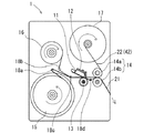
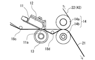
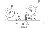
本実施例1に係るサーマルプリンタ1は、図1及び2に示すように、サーマルヘッド11と、サーマルヘッド11を予熱するヘッドヒータ12と、サーマルヘッド11の押圧部11aによる押圧力を受ける支持ローラ13と、記録媒体である装飾用リボン21をサーマルヘッド11に対して相対移動させるピンチローラ14とを備えている。
Example 1
(1) Configuration of Embodiment 1 As shown in FIGS. 1 and 2, the thermal printer 1 according to Embodiment 1 includes a
サーマルヘッド11は、エッジ型サーマルヘッドとしている。また、サーマルヘッド11は、その押圧部11aに、複数の発熱体が印字方向と直交する方向に直線状に配列されている。サーマルヘッド11の押圧力は、発熱体25.4mm(1インチ)幅あたり9.8〜24.5Nと、通常の熱転写プリンタにおけるサーマルヘッドの押圧力と比較して大きく設定されている。そして、発熱体は、上記の押圧力がかかった状態で、パーソナルコンピュータ等からの入力信号を受けて発熱する。
ヘッドヒータ12は、サーマルヘッド11と一体に設けられており、サーマルヘッド11を40〜70℃に予熱する。
支持ローラ13は、装飾用リボン21及び保護シート22を介して、サーマルヘッド11の押圧部11aの押圧力を受けるように回転自在に設けられている。また、支持ローラ13のローラ表面には、シリコン樹脂がライニングされている。
ピンチローラ14は、上側ローラ14a及び下側ローラ14bを有しており、これらにより、装飾用リボン21及び保護シート22を挟持する。そして、この挟持した状態で、図示しない駆動源により回転して、装飾用リボン21及び保護シート22を送り出す。
The
The
The
The
装飾用リボン21は、長尺帯状のナイロン製サテン織リボンを用いている。この装飾用リボン21は、リボンローラ15にロール状に巻き回されており、第1補助ローラ18a、第2補助ローラ18b、支持ローラ13、第3補助ローラ18cを経てピンチローラ14に挟持されている。そして、装飾用リボン21は、ピンチローラ14が回転することにより送り出され、サーマルヘッド11に対して相対的に移動する。
保護シート22は、長尺帯状のPET製としている。この保護シート22は、送りローラ16にロール状に巻き回されており、第4補助ローラ18d、第2補助ローラ18b、支持ローラ13を経て、装飾用リボン21と共にピンチローラ14に挟持されている。ピンチローラ14から送り出された保護シート22は、図示しない駆動源を有する巻取ローラ17に巻き取られる。また、保護シート22は、第2補助ローラ18bから支持ローラ13の間で装飾用リボン21と重ね合わされており、装飾用リボン21と共にサーマルヘッド11の押圧部11aによる押圧力を受けている。そして、装飾用リボン21は支持ローラ13と、保護シート22はサーマルヘッド11の押圧部11aと、それぞれ接した状態で挟持されている。更に、保護シート22は、支持ローラ13からピンチローラ14の間で、装飾用リボン21が第3補助ローラ18cにより下方へ迂回しているため、装飾用リボン21から離隔されている。
また、サーマルプリンタ1は、上記各部を制御し、印字パターンの形成を実行させる図示しない制御部を備えている。
The
The
Further, the thermal printer 1 includes a control unit (not shown) that controls the above-described units and executes formation of a print pattern.
(2)実施例1の作用
次に、このように構成された実施例1のサーマルプリンタ1を使用して装飾用リボン21の表面に印字パターンを形成する方法を説明する。
最初に、装飾用リボン21及び保護シート22を、上述のように、所定の経路で各ローラに巻き回す。また、ヘッドヒータ12によりサーマルヘッド11を予熱しておく。準備が完了したら印字を開始する。
(2) Operation of Example 1 Next, a method of forming a print pattern on the surface of the
First, the
印字が開始されると、ピンチローラ14が回転する。ピンチローラ14に挟持されている装飾用リボン21及び保護シート22は、図1の右方向へ、所定の速度で送り出される。支持ローラ13は、保護シート22及び装飾用リボン21を介してのサーマルヘッド11からの押圧力を受けた状態で、送り出される装飾用リボン21に従動して回転する。それと同時に、サーマルヘッド11の押圧部11aに配列された発熱体は、押圧部11aの押圧力が付与された状態で、印字データに基づいて制御部から出力される所定の電圧の大きさ及び電圧印加時間で通電され、選択的な発熱が実行される。
発熱体で発生した熱は、保護シート22を介して装飾用リボン21に伝導する。そして装飾用リボン21は、伝導した熱により、その表面が軟化、溶融され、表面が平滑化される。この平滑化された表面が印字パターンとなる。
When printing is started, the
The heat generated by the heating element is conducted to the
印字パターンが形成され、サーマルヘッド11及び支持ローラ13を通過した装飾用リボン21は、保護シート22との癒着を防止するために、第3補助ローラ18cにより、一旦保護シート22から剥離される。その後、ピンチローラ14を通過して下側ローラ14b側へ排出される。一方、ピンチローラ14を通過した保護シート22は、上側ローラ14a側へ排出され、巻取ローラ17に巻き取られる。
尚、所定の印字が完了した後もピンチローラ14は引き続き回転する。ピンチローラ14の回転は、装飾用リボン21の印字パターンが形成された箇所がピンチローラ14を通過し、所定の送り量を送り終えたところで停止される。
The
Note that the
(3)実施例1の効果
以上より、本実施例1によると、サーマルヘッド11を用いて、装飾用リボン21の表面を軟化、溶融して平滑化させて印字パターンが形成される。このように、記録媒体である装飾用リボン21の表面状態を変化させることにより印字パターンを形成しているので、従来のように、転写箔の転写層を記録媒体に転写することにより印字パターンを形成する印字方法と比較して、従来にない新規な美観を備える印字を実現できる。また、インクリボン等の転写箔を用いないので、ランニングコストを抑えることができる。
(3) Effects of Example 1 As described above, according to Example 1, the print pattern is formed by using the
また、本実施例1では、記録媒体である装飾用リボン21よりも表面が滑らかな保護シート22を用いて印字を行うので、装飾用リボン21が直接サーマルヘッド11の押圧部11aに接触して摺動する場合と比較して、押圧部11aの磨耗を抑制することができ、また、記録媒体上に付着している塵、溶融した記録媒体自体等の異物がサーマルヘッドに付着し、熱の伝達を妨げることによる筋状の印字不良を防止することができる。また、保護シート22は、押圧部11aとの摺動による磨耗等により劣化するまで、繰り返し利用することができる。
更に、本実施例1では、サーマルヘッド11をヘッドヒータ12により予熱するようにしたので、サーマルヘッド11の発熱体の発熱がサーマルヘッド11自体を昇温させることなく、転写箔を転写する場合と比較してより多くの熱エネルギを必要とする、装飾用リボン21の表面を軟化、溶融させるための十分な熱エネルギを装飾用リボン21に付与することができ、効果的に印字パターンを形成することができる。
In the first embodiment, printing is performed using the
Furthermore, in the first embodiment, since the
(実施例2)
次に、実施例2に係るサーマルヘッドを用いた印字方法について説明する。本実施例2に係る印字方法は、アルミニウムの転写層を備える金属転写箔を用いて、記録媒体である装飾用リボンに転写層を転写してなる印字パターン形成を例示して説明する。
尚、本実施例2に係るサーマルプリンタにおいて上記実施例1のサーマルプリンタ1と略同じ構成部分は、同符号を付け詳説を省略する。
(Example 2)
Next, a printing method using the thermal head according to the second embodiment will be described. The printing method according to the second embodiment will be described by exemplifying print pattern formation in which a transfer layer is transferred to a decorative ribbon as a recording medium using a metal transfer foil having an aluminum transfer layer.
In the thermal printer according to the second embodiment, the same components as those of the thermal printer 1 of the first embodiment are denoted by the same reference numerals, and detailed description thereof is omitted.
(1)実施例2の構成
本実施例2に係るサーマルプリンタ1は、図1及び2に示すように、サーマルヘッド11と、サーマルヘッド11を予熱するヘッドヒータ12と、サーマルヘッド11の押圧部11aによる押圧力を受ける支持ローラ13と、記録媒体である装飾用リボン21をサーマルヘッド11に対して相対移動させるピンチロ−ラ14とを備えている点は実施例1と同様であるが、実施例1の保護シートに換えて、転写箔42が用いられている。即ち、本実施例2では、サーマルヘッドを用いた印字方法であって、転写箔を用いて記録媒体に転写層を転写してなる印字パターンを形成する印字方法を説明する。
また、本実施例2に係るサーマルプリンタ1は、更に、図3に示す制御部30を備えている。
(1) Configuration of Example 2 As shown in FIGS. 1 and 2, the thermal printer 1 according to Example 2 includes a
The thermal printer 1 according to the second embodiment further includes a
転写箔42は、アルミニウムの転写層を備える金属転写箔を用いている。この転写箔42は、実施例1の保護シート22と同様に、送りローラ16にロール状に巻き回されており、第4補助ローラ18d、第2補助ローラ18b、支持ローラ13を経て、装飾用リボン21と共にピンチローラ14に挟持されている。ピンチローラ14から送り出された転写箔42は、図示しない駆動源を有する巻取ローラ17に巻き取られる。また、転写箔42は、第2補助ローラ18bから支持ローラ13の間で装飾用リボン21と重ね合わされており、装飾用リボン21と共にサーマルヘッド11の押圧部11aによる押圧力を受けている。そして、装飾用リボン21は支持ローラ13と、転写箔42はサーマルヘッド11の押圧部11aと、それぞれ接した状態で挟持されている。更に、転写箔42は、支持ローラ13からピンチローラ14の間で、装飾用リボン21が第3補助ローラ18cにより下方へ迂回しているため、装飾用リボン21から離隔されている。
The
この転写箔42は、図4に示すように、PET製の基材42aの表面に順次離型層42b、転写層42c及び接着層42dが積層された構造となっている。転写箔42は、基材42aが約12μm、転写層42cが約0.9μmの厚さを有し、一般的な熱転写に使用されるインクリボンが全体で2.5〜6μmであるのと比較して相当厚いものとなっている。したがって、相当の熱エネルギを加えないと転写箔42の離型層42b及び接着層42dが活性化せず、転写層42cが離型層42bから剥離しにくいものとなっている。
As shown in FIG. 4, the
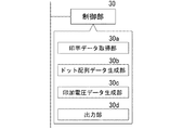
制御部30は、図3に示すように、印字データ取得部30aと、ドット配列データ生成部30bと、印加電圧データ生成部30cと、出力部30dとを備えている。
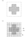
印字データ取得部30aは、図示しない入力手段により入力される、印字データ(図5(a)参照)を取得する。この取得する印字データは、ドットの集合である印字パターンの全体形状に相当するものである。
As shown in FIG. 3, the
The print
ドット配列データ生成部30bは、印字データ取得部30aが取得した印字データに基づいて、装飾用リボン21に転写されて形成されるドットの配列を表すデータを生成する。即ち、ドット配列データは、印字パターンがどのようなドット構成で形成されるかを表すデータである。例えば、図5(a)のような「十」を印字パターンとして形成する場合、「十」をどのようなドット構成で形成するかを表したものが図5(b)であり、ドット配列データに相当する。ここで、図5(b)の各マス目は、それぞれ1ドットを表し、各マス目において、白マスはドットを形成しない箇所、ハッチングのかかったマス目はドットを形成する箇所をそれぞれ表している。
The dot array
印加電圧データ生成部30cは、ドット配列データが示すドットの配列状態から、各ドット形成のために発熱体に印加する電圧の大きさを設定し、印加電圧データを生成する。即ち、ドット配列データにおける各ドットについて、印字パターンのどの位置を構成するドットであるかを把握し、その位置によって、印加する電圧の大きさをそれぞれ設定したデータを生成する。各ドットが印字パターンのどの位置を構成するドットであるかは、当該ドットの周囲のドット形成の有無を参照して判別される。本実施例2では、参照するドットは、当該ドットの印字方向上流側(当該ドットより先に印字されるドット側)の3ドット、印字方向下流側の2ドット、印字方向に直交する方向の両側各2ドットの合計9ドットである。
The applied voltage
例えば、図5(b)に示すドットDa〜Dcの場合、参照するドットは、それぞれ図6(a)〜(c)のようになる。このようにして、ドットDaは印字パターンの角部を構成するドット、Dbは印字パターンの端部を構成するドット、Dcは印字パターンの内部を構成するドットであることが判別できる。そして、角部及び端部等の印字パターンの輪郭を構成するドットの形成にはより多くの熱エネルギを付与し、転写層42cをより強固に装飾用リボン21に接着させるようにする。ここで、印加する電圧の大きさは、図6(a)〜(c)に例示した参照ドットの有無パターンのすべての組み合わせ(29通り)について予め対応させて決定されている。尚、上述のDa〜Dcのドット形成のために付与する熱量の大きさHa〜Hcを比較すると、Ha>Hb>Hcとなる。
出力部30dは、上記のようにして生成したドット配列データ及び印加電圧データに基づいて、発熱体に印加する所定の大きさ、印加時間の電圧を、所定のタイミングで出力する。
For example, in the case of dots Da to Dc shown in FIG. 5B, the dots to be referred to are as shown in FIGS. 6A to 6C, respectively. In this way, it can be determined that the dot Da is a dot constituting the corner of the print pattern, Db is a dot constituting the end of the print pattern, and Dc is a dot constituting the inside of the print pattern. Then, more thermal energy is applied to the formation of dots constituting the outline of the print pattern such as corners and edges, and the
Based on the dot arrangement data and the applied voltage data generated as described above, the
更に、本実施例2に係る印字方法では、図7(a)に示すように、装飾用リボン21の1ドットあたりの移動時間と等しい印加時間であり、且つ、段階的に小さくなる電圧が印加されることにより1つのドットが形成される。即ち、本実施例2では、1つのドットを形成する際、その次のドットを形成する電圧印加のタイミングまで、連続的な電圧印加及び段階的に電圧が小さくなる電圧印加を行っている。また、段階的に小さくなる電圧の各段の幅(時間)は、1ドットあたりの電圧印加幅(時間)を31等分したものとしている。そして、各電圧の大きさは、上述のように、印加電圧データ生成部30cにより生成される印加電圧データに基づいて設定されるが、図7(a)に示すように、1ドットを形成する電圧印加のうちの、1段目の電圧がもっとも大きく、2段目、3段目、4段目と、徐々に小さくなり、4段目以降は一定となる。そして、例えば、このような電圧印加方法で3個の隣接したドットから構成される印字パターンを形成すると、図7(a)に示すように、ドット同士が結合された印字パターンとなる。一方、インクリボンを転写箔として用いた一般的な印字方法の場合、図7(b)に示すように、連続したドットを形成する際の電圧印加は断続的であり、その次のドットを形成する電圧印加のタイミングまでの間隔は、印加される電圧の印加時間と比較して極めて大きい。そして、そのような電圧印加方法により、上記と同様に、3個の隣接したドットから構成される印字パターンを形成すると、図7(b)に示すように、各ドットがそれぞれ独立した点状となる印字パターンとなる。
Furthermore, in the printing method according to the second embodiment, as shown in FIG. 7A, a voltage that is equal to the moving time per dot of the
(2)実施例2の作用
次に、このように構成された実施例2のサーマルプリンタ1を使用して装飾用リボン21の表面に金属転写層を転写してなる印字パターンを形成する方法を説明する。
最初に、印字パターンデータ及び印加電圧データの生成方法について説明する。
まず、制御部30は、印字データ取得部30aにより、入力手段から入力される印字データを取得する。次に、ドット配列データ生成部30bは、上記取得した印字データに基づいて、ドット配列データを生成する。そして、印加電圧データ生成部30cは、ドット配列データに基づいて、各ドットについて、ドット形成のためにサーマルヘッド11の発熱体に印加する電圧を設定した印加電圧データを生成する。このように、制御部30により、ドット配列データ及び印加電圧データを予め生成しておく。
(2) Operation of Embodiment 2 Next, a method of forming a print pattern formed by transferring a metal transfer layer onto the surface of the
First, a method for generating print pattern data and applied voltage data will be described.
First, the
一方、サーマルプリンタ1は、装飾用リボン21及び転写箔42を、上述のように、所定の経路で各ローラに巻き回す。また、ヘッドヒータ12によりサーマルヘッド11を予熱しておく。準備が完了したら印字を開始する。
On the other hand, the thermal printer 1 winds the
印字が開始されると、ピンチローラ14が回転する。ピンチローラ14に挟持されている装飾用リボン21及び転写箔42は、図1の右方向へ、所定の速度で送り出される。支持ローラ13は、転写箔42及び装飾用リボン21を介してのサーマルヘッド11からの押圧力を受けた状態で、送り出される装飾用リボン21に従動して回転する。それと同時に、サーマルヘッド11の押圧部11aに配列された発熱体は、押圧部11aの押圧力が付与された状態で、制御部30の出力部30dから出力されるドット配列データ及び印加電圧データに基づいて通電され、選択的な発熱が実行される。
When printing is started, the
上述のように各発熱体で発生した熱は、転写箔42に伝導する。そして転写箔42は、伝導した熱により、離型層42b及び接着層42dがそれぞれ軟化、溶融され、離型層42bは転写層42cとの接着が弱まり、接着層42dは装飾用リボン21の表面に接着する。
サーマルヘッド11及び支持ローラ13を通過した装飾用リボン21は、接着層42dによりその表面に接着された転写層42cを、基材42aから剥離し且つ基材42a側に残る転写されない転写層42cから分断するために、第3補助ローラ18cにより、転写箔42から離れる方向へ送り出される。その後、ピンチローラ14を通過して下側ローラ14b側へ排出される。一方、ピンチローラ14を通過した保護シート22は、上側ローラ14a側へ排出され、巻取ローラ17に巻き取られる。
尚、所定の印字が完了した後もピンチローラ14は引き続き回転する。ピンチローラ14の回転は、装飾用リボン21の印字パターンが形成された箇所がピンチローラ14を通過し、所定の送り量を送り終えたところで停止される。
As described above, the heat generated in each heating element is conducted to the
The
Note that the
(3)実施例2の効果
以上より、本実施例2によると、サーマルヘッド11を用いて、装飾用リボン21の表面に、金属箔を備える転写層42cを転写して印字パターンが形成される。このとき、印字パターンの輪郭近傍を構成するドットには、印字パターンの中心付近を構成するドットと比較して、より大きな熱エネルギを付与して、接着層42dが装飾用リボン21により強固に接着するようにしている。これにより、印字パターンの輪郭近傍のドットをとなる転写層をより強固に接着させ、転写箔の基材側に残る転写されない転写層から正確に分断させることができ、転写された転写層42cからなる印字パターンの輪郭をより明瞭にすることができる。
(3) Effects of Example 2 As described above, according to Example 2, the
また、各ドットの相対移動方向の前方3つ、後方2つ、及び相対移動方向に直交する方向の両方各2つの計9つのドットの有無を参照して当該ドットの印字パターンにおける位置を判別するようにしたので、各ドットが印字パターンのどの位置を構成するドットであるのかを正確且つ高速に把握することができる。 Further, the positions of the dots in the print pattern are discriminated by referring to the presence or absence of a total of nine dots, both in the front three in the relative movement direction, in the rear two, and in the direction orthogonal to the relative movement direction. Since it did in this way, it can grasp | ascertain accurately and at high speed which position of each dot each dot comprises.
更に、本実施例2では、1つのドットを形成する際、その次のドットを形成するための電圧印加のタイミングまで、連続した電圧印加且つ電圧の大きさが段階的に小さくなる電圧印加を行うようにしたので、各ドットを他の隣接するドットと結合させて形成し、且つ尾引きも生じない印字パターンを形成することができ、各ドットの境界に継ぎ目やしわのない、一体化され全面が金属光沢を有する美しい印字パターンを形成することができると共に、。 Further, in the second embodiment, when forming one dot, continuous voltage application and voltage application in which the magnitude of the voltage is gradually reduced are performed until the voltage application timing for forming the next dot. As a result, it is possible to form a print pattern in which each dot is combined with other adjacent dots and no tailing occurs, and there is no seam or wrinkle at the boundary of each dot. As well as being able to form beautiful printed patterns with metallic luster.
また、本実施例2では、サーマルヘッド11をヘッドヒータ12により予熱するようにしたので、サーマルヘッド11の発熱体の発熱がサーマルヘッド11自体を昇温させることなく、転写箔を転写する場合と比較してより多くの熱エネルギを必要とする、装飾用リボン21の表面を軟化、溶融させるための十分な熱エネルギを装飾用リボン21に付与することができ、効果的に印字パターンを形成することができる。
In the second embodiment, since the
(他の実施例)
本発明においては、上記実施例1及び2に限られず、目的、用途に応じて本発明の範囲内で、種々変更した実施例とすることができる。即ち、上記実施例1では、保護シート22を用いて、記録媒体である装飾用リボン21の表面状態を変化させて印字パターンを形成するようにしたが、これに限定されず、保護シート22を用いずに、サーマルヘッド11の押圧部11aを直接装飾用リボン21の表面に接触させて摺動させ、印字パターンを形成するようにしてもよい。
(Other examples)
In the present invention, the present invention is not limited to the first and second embodiments, and various modified embodiments can be made within the scope of the present invention depending on the purpose and application. That is, in Example 1 described above, the
また、上記実施例1及び2では、記録媒体として、ナイロン製サテン織の長尺帯状の装飾用リボン21を用いるようにしたが、これに限定されず、ポリエステル製、ウレタン製等の樹脂繊維を織ってなるリボンを用いてもよいし、その形状を、矩形状、円形状の織物等としてもよい。更に、織物にも限定されず、シート状等を用いてもよい。また、材質も樹脂に限定されず、ゴム、皮革、合成皮革等であってもよい。
In Examples 1 and 2, the long
また、上記実施例2では、金属転写箔を用いて印字パターンを形成するようにしたが、これに限定されず、実施例1と同様に、記録媒体の表面状態を変化させて印字パターンを形成するようにしてもよい。これにより、各ドットを他の隣接するドットと結合させて形成した印字パターンを形成することができ、各ドットの境界に継ぎ目のない(点の集合でない)、一体化された印字パターンを形成することができると共に、印字パターンの輪郭近傍を構成するドットには、印字パターンの中心付近を構成するドットと比較してより大きな熱エネルギを付与するようにして、その外側領域の、熱により軟化、溶融していない部分における記録媒体の表面状態との差異を明瞭に表すことができ、印字パターンの輪郭をより明瞭にすることができる。 In the second embodiment, the print pattern is formed using the metal transfer foil. However, the present invention is not limited to this, and the print pattern is formed by changing the surface state of the recording medium as in the first embodiment. You may make it do. As a result, it is possible to form a print pattern formed by combining each dot with other adjacent dots, and form an integrated print pattern that is seamless (not a set of dots) at the boundary of each dot. In addition, the dots constituting the vicinity of the outline of the print pattern can be applied with greater thermal energy than the dots constituting the vicinity of the center of the print pattern, and the outer area is softened by heat. The difference from the surface state of the recording medium in the unmelted portion can be clearly expressed, and the outline of the print pattern can be made clearer.
更に、上記実施例2では、制御部30により、各ドットについて、印加電圧の大きさをそれぞれ設定して、ドット形成のために付与する熱量を調整したが、これに限定されず、例えば、図7(b)のように、断続的な電圧印加を行う場合には、印加電圧の大きさだけでなく、印加時間についても個々に設定するようにしてもよい。これにより、各ドット形成のための発熱体の発熱による熱量を適宜調整することができる。
Furthermore, in the second embodiment, the
また、上記実施例1及び2では、サーマルヘッド11を固定し、記録媒体である装飾用リボン21を搬送することにより、サーマルヘッド及び記録媒体を相対的に移動させるようにしたが、これに限定されず、サーマルヘッドを移動可能に設け、記録媒体を固定して配置することにより、サーマルヘッド及び記録媒体を相対的に移動させるようにしてもよい。このような形態を、図8に示すサーマルプリンタ50を例として説明する。
In the first and second embodiments, the
図8に示すサーマルプリンタ50は、サーマルヘッド51と、サーマルヘッド51を予熱するヘッドヒータ52と、記録媒体である樹脂シート61が載置されて支持される支持部53と、転写箔42を予熱する箔ヒータ59とを備えている。また、サーマルプリンタ50は、実施例2と同様に、制御部30を備え、実施例2と同様の制御により印字パターンを形成する。
A
サーマルヘッド51は、端面型サーマルヘッドとしている。また、サーマルヘッド51は、実施例1及び2と同様に、その押圧部51aに、複数の発熱体が印字方向と直交する方向に直線状に配列されている。サーマルヘッド51の押圧力は、実施例1及び2と同様に、一般的な押圧力と比較して大きい、発熱体25.4mm(1インチ)幅あたり9.8〜24.5Nに設定されている。そして、発熱体は、上記の押圧力がかかった状態で、パーソナルコンピュータ等からの入力信号を受けて発熱する。
The
ヘッドヒータ52は、実施例1及び2と同様に、サーマルヘッド51と一体に設けられており、サーマルヘッド51を40〜70℃に予熱する。
支持部53は、樹脂シート61及び転写箔42を介して、サーマルヘッド51の押圧部51aの押圧力を受けるように移動不能に設けられている。
箔ヒータ59は、サーマルヘッド51に対して、印字方向の上流側に設けられており、支持部53に載置された樹脂シート61の上側に重ね合わされた転写箔42を40〜80℃に予熱する。
As in the first and second embodiments, the
The
The
転写箔42は、送りローラ56にロール状に巻き回されており、第1補助ローラ58a、第2補助ローラ58b、第3補助ローラ58c、第4補助ローラ58dを経て、図示しない駆動源を有する巻取ローラ57に巻き取られる。また、転写箔42は実施例2と同じ金属転写箔を用いている。
樹脂シート61は、長方形状のポリプロピレン製である。
The
The
サーマルヘッド51は移動可能に設けられており、印字の際には、図8の左方向へ移動する。樹脂シート61は、支持部53に載置されて固定されている。このような構成により、サーマルヘッド51は、記録媒体である樹脂シート61に対して相対的に移動する。また、転写箔42が巻き回されている送りローラ56、第1補助ローラ58a、第2補助ローラ58b、第3補助ローラ58c、第4補助ローラ58d及び巻取ローラ57は、サーマルヘッド51と共にヘッドユニットを構成しており、サーマルヘッド51の移動に伴って移動する。更に、転写箔42は、巻取ローラ57の駆動源及び送りローラ56のブレーキを制御することによってその張力が調整されていると共に、印字の際には、第2補助ローラ58bと第3補助ローラ58cの間において、記録媒体に対して相対的に不動且つサーマルヘッド51に対して相対的に移動するように、巻取ローラ57に巻き取られる。
The
上述のように、サーマルヘッドを移動可能に設け、記録媒体を固定して配置することにより、サーマルヘッド及び記録媒体を相対的に移動させるようにした形態のサーマルプリンタであっても、上記実施例1及び2と同様の印字方法を実現できる。
また、上述の実施形態では、金属転写箔を転写して印字パターンを形成するようにしたが、これに限定されず、実施例1と同様に、記録媒体である樹脂シート61の表面状態を変化させて印字パターンを形成するようにしてもよく、この場合、実施例1と同様に、保護シートを介しての印字でもよいし、保護シートを用いなくてもよい。
更に、上述の実施形態では、記録媒体として、長方形状のポリプロピレン製樹脂シート61を用いたが、形状、材質等も、これに限定されず、円形状、長尺帯状等、ゴム、皮革、合成皮革等としてもよい。
As described above, even in the case of a thermal printer in which the thermal head and the recording medium are relatively moved by providing the thermal head so as to be movable and fixing the recording medium, the above-described embodiment The same printing method as in 1 and 2 can be realized.
In the above embodiment, the metal transfer foil is transferred to form the print pattern. However, the present invention is not limited to this, and the surface state of the
Furthermore, in the above-described embodiment, the rectangular
1、50;サーマルプリンタ、11、51;サーマルヘッド、11a、51a;押圧部、12、52;ヘッドヒータ、13;支持ローラ、14;ピンチローラ、14a;上側ローラ、14b;下側ローラ、15;リボンローラ、16、56;送りローラ、17、57;巻取ローラ、18a、58a;第1補助ローラ、18b、58b;第2補助ローラ、18c、58c;第3補助ローラ、18d、58d;第4補助ローラ、21;装飾用リボン、22;保護シート、30;制御部、30a;印字データ取得部、30b;ドット配列データ生成部、30c;印加電圧データ生成部、30d;出力部、42;転写箔、42a;基材、42b;離型層、42c;転写層、42d;接着層、53;支持部、59;箔ヒータ、61;樹脂シート、D、D1、D2、D3;ドット、P;印字パターン。
DESCRIPTION OF
Claims (34)
前記発熱体の発熱により前記記録媒体の表面状態を変化させ、該記録媒体からなる前記ドットを形成することを特徴とするサーマルヘッドを用いた印字方法。 In a state where the recording medium is pressed by a thermal head having a plurality of heating elements arranged in a straight line, each heating element is selectively heated by applying a voltage, and the thermal head and the recording medium are relative to each other. A printing method for forming dots on the recording medium corresponding to heat generated by the heating elements, and forming a printing pattern composed of the dots,
A printing method using a thermal head, wherein the dots of the recording medium are formed by changing the surface state of the recording medium by heat generated by the heating element.
前記各ドットは、それぞれ前記相対移動の1ドットあたりの移動時間と等しい時間連続して前記電圧が印加されて形成されることを特徴とするサーマルヘッドを用いた印字方法。 In a state where the recording medium is pressed by a thermal head having a plurality of heating elements arranged in a straight line, each heating element is selectively heated by applying a voltage, and the thermal head and the recording medium are relative to each other. A printing method for forming dots on the recording medium corresponding to heat generated by the heating elements, and forming a printing pattern composed of the dots,
Each of the dots is formed by applying the voltage continuously for a time equal to a movement time per dot of the relative movement.
前記印字パターンの形状の情報である印字データを取得する印字データ取得工程と、
前記印字データに基づいて、前記記録媒体に形成されるドットの配列情報であるドット配列データを生成するドット配列データ生成工程と、
前記ドット配列データに基づいて、前記各ドットの周囲に形成されるドットの有無を参照して前記各発熱体に印加する電圧の大きさ及び/又は印加時間をそれぞれ設定し、印加電圧データを生成する印加電圧データ生成工程と、
前記ドット配列データ及び前記印加電圧データに基づいて、前記各発熱体を発熱させる信号を出力する出力工程と、を備えることを特徴とするサーマルヘッドを用いた印字方法。 In a state where the recording medium is pressed by a thermal head having a plurality of heating elements arranged in a straight line, each heating element is selectively heated by applying a voltage, and the thermal head and the recording medium are relative to each other. A printing method for forming dots on the recording medium corresponding to heat generated by the heating elements, and forming a printing pattern composed of the dots,
A print data acquisition step of acquiring print data which is information of the shape of the print pattern;
A dot array data generation step for generating dot array data, which is array information of dots formed on the recording medium, based on the print data;
Based on the dot arrangement data, reference is made to the presence or absence of dots formed around each dot, and the magnitude and / or application time of the voltage to be applied to each heating element is set to generate application voltage data. The applied voltage data generation step,
A printing method using a thermal head, comprising: an output step of outputting a signal for causing the heating elements to generate heat based on the dot arrangement data and the applied voltage data.
前記印字パターンの形状の情報である印字データを取得する印字データ取得工程と、
前記印字データに基づいて、前記記録媒体に形成されるドットの配列情報であるドット配列データを生成するドット配列データ生成工程と、
前記ドット配列データに基づいて、前記各ドットの周囲に形成されるドットの有無を参照して前記各発熱体に印加する電圧の大きさを設定し、印加電圧データを生成する印加電圧データ生成工程と、
前記ドット配列データ及び前記印加電圧データに基づいて、前記各発熱体を発熱させる信号を出力する出力工程と、を備え、
前記各ドットは、それぞれ前記相対移動の1ドットあたりの移動時間と等しい時間連続して前記電圧が印加されて形成されると共に、前記電圧の大きさを段階的に小さくして形成され、
前記参照に用いられるドットの有無は、少なくとも前記各ドットの前記相対移動方向の前方3つ、後方2つ、及び該相対移動方向に直交する方向の両方各2つの計9つのドットの有無であり、
前記ドットは、前記発熱体の発熱により前記記録媒体の表面状態を変化させて形成される該記録媒体からなるドットであり、
前記ドットは、前記サーマルヘッド及び前記記録媒体の間に設けられ且つ前記サーマルヘッドに対して相対的に移動する保護シートを介して形成され、
前記記録媒体は、樹脂繊維を織ってなる装飾用リボンであることを特徴とするサーマルヘッドを用いた印字方法。 In a state where the recording medium is pressed by a thermal head having a plurality of heating elements arranged in a straight line, each heating element is selectively heated by applying a voltage, and the thermal head and the recording medium are relative to each other. A printing method for forming dots on the recording medium corresponding to heat generated by the heating elements, and forming a printing pattern composed of the dots,
A print data acquisition step of acquiring print data which is information of the shape of the print pattern;
A dot array data generation step for generating dot array data, which is array information of dots formed on the recording medium, based on the print data;
An applied voltage data generation step of setting applied voltage data by setting the magnitude of the voltage applied to each heating element with reference to the presence or absence of dots formed around each dot based on the dot arrangement data When,
An output step for outputting a signal for heating each heating element based on the dot arrangement data and the applied voltage data, and
Each of the dots is formed by applying the voltage continuously for a time equal to the movement time per dot of the relative movement, and by decreasing the magnitude of the voltage stepwise.
The presence / absence of dots used for the reference is the presence / absence of a total of nine dots, at least three in each of the dots in the relative movement direction, two in the rear, and two in the direction perpendicular to the relative movement direction. ,
The dot is a dot formed of the recording medium formed by changing the surface state of the recording medium by heat generation of the heating element,
The dots are formed via a protective sheet that is provided between the thermal head and the recording medium and moves relative to the thermal head,
A printing method using a thermal head, wherein the recording medium is a decorative ribbon made of woven resin fibers.
前記サーマルヘッドと記録媒体とを相対的に移動させる移動手段と、を備え、
前記サーマルヘッドにより前記記録媒体を押圧した状態で、電圧を印加することにより前記各発熱体を選択的に発熱させると共に前記移動手段により該サーマルヘッドと該記録媒体とを相対的に移動させ、該各発熱体の発熱にそれぞれ対応したドットを該記録媒体に形成し、該各ドットから構成される印字パターンを形成する印字装置であって、
前記発熱体の発熱により前記記録媒体の表面状態を変化させ、該記録媒体からなる前記ドットを形成することを特徴とする印字装置。 A thermal head having a plurality of heating elements arranged in a straight line;
Moving means for relatively moving the thermal head and the recording medium,
In a state where the recording medium is pressed by the thermal head, each heating element is selectively heated by applying a voltage, and the thermal head and the recording medium are relatively moved by the moving means, A printing apparatus that forms dots corresponding to the heat generation of each heating element on the recording medium and forms a printing pattern composed of the dots,
A printing apparatus, wherein the dots formed of the recording medium are formed by changing a surface state of the recording medium by heat generation of the heating element.
前記サーマルヘッドと記録媒体とを相対的に移動させる移動手段と、を備え、
前記サーマルヘッドにより前記記録媒体を押圧した状態で、電圧を印加することにより前記各発熱体を選択的に発熱させると共に前記移動手段により該サーマルヘッドと該記録媒体とを相対的に移動させ、該各発熱体の発熱にそれぞれ対応したドットを該記録媒体に形成し、該各ドットから構成される印字パターンを形成する印字装置であって、
前記各発熱体の選択的な発熱は、1ドットあたりの電圧印加時間が前記相対移動の1ドットあたりの移動時間と等しい電圧印加による発熱であることを特徴とする印字装置。 A thermal head having a plurality of heating elements arranged in a straight line;
Moving means for relatively moving the thermal head and the recording medium,
In a state where the recording medium is pressed by the thermal head, each heating element is selectively heated by applying a voltage, and the thermal head and the recording medium are relatively moved by the moving means, A printing apparatus that forms dots corresponding to the heat generation of each heating element on the recording medium and forms a printing pattern composed of the dots,
The printing apparatus according to claim 1, wherein the selective heat generation of each of the heating elements is heat generation by applying a voltage equal to a voltage application time per dot equal to a movement time per dot of the relative movement.
前記サーマルヘッドと記録媒体とを相対的に移動させる移動手段と、を備え、
前記サーマルヘッドにより前記記録媒体を押圧した状態で、電圧を印加することにより前記各発熱体を選択的に発熱させると共に前記移動手段により該サーマルヘッドと該記録媒体とを相対的に移動させ、該各発熱体の発熱にそれぞれ対応したドットを該記録媒体に形成し、該各ドットから構成される印字パターンを形成する印字装置であって、
前記印字パターンの形状の情報である印字データを取得する印字データ取得部と、
前記印字データに基づいて、前記記録媒体に形成されるドットの配列情報であるドット配列データを生成するドット配列データ生成部と、
前記ドット配列データに基づいて、前記各ドットの周囲に形成されるドットの有無を参照して前記各発熱体に印加する電圧の大きさ及び/又は印加時間をそれぞれ設定し、印加電圧データを生成する印加電圧データ生成部と、
前記ドット配列データ及び前記印加電圧データに基づいて、前記各発熱体を発熱させる信号を出力する出力部と、を備えることを特徴とする印字装置。 A thermal head having a plurality of heating elements arranged in a straight line;
Moving means for relatively moving the thermal head and the recording medium,
In a state where the recording medium is pressed by the thermal head, each heating element is selectively heated by applying a voltage, and the thermal head and the recording medium are relatively moved by the moving means, A printing apparatus that forms dots corresponding to the heat generation of each heating element on the recording medium and forms a printing pattern composed of the dots,
A print data acquisition unit for acquiring print data which is information on the shape of the print pattern;
A dot array data generation unit that generates dot array data, which is array information of dots formed on the recording medium, based on the print data;
Based on the dot arrangement data, reference is made to the presence or absence of dots formed around each dot, and the magnitude and / or application time of the voltage to be applied to each heating element is set to generate application voltage data. An applied voltage data generation unit,
And an output unit that outputs a signal for causing each of the heating elements to generate heat based on the dot arrangement data and the applied voltage data.
前記サーマルヘッドと記録媒体とを相対的に移動させる移動手段と、を備え、
前記サーマルヘッドにより前記記録媒体を押圧した状態で、電圧を印加することにより前記各発熱体を選択的に発熱させると共に前記移動手段により該サーマルヘッドと該記録媒体とを相対的に移動させ、該各発熱体の発熱にそれぞれ対応したドットを該記録媒体に形成し、該各ドットから構成される印字パターンを形成する印字装置であって、
前記印字パターンの形状の情報である印字データを取得する印字データ取得部と、
前記印字データに基づいて、前記記録媒体に形成されるドットの配列情報であるドット配列データを生成するドット配列データ生成部と、
前記ドット配列データに基づいて、前記各ドットの周囲に形成されるドットの有無を参照して前記各発熱体に印加する電圧の大きさを設定し、印加電圧データを生成する印加電圧データ生成部と、
前記ドット配列データ及び前記印加電圧データに基づいて、前記各発熱体を発熱させる信号を出力する出力部と、を備え、
前記各発熱体の選択的な発熱は、1ドットあたりの電圧印加時間が前記相対移動の1ドットあたりの移動時間と等しく、且つ、印加される前記電圧の大きさが段階的に小さくなる電圧印加による発熱であり、 前記印加電圧データ生成部は、少なくとも前記各ドットの前記相対移動方向の前方3つ、後方2つ、及び該相対移動方向に直交する方向の両方各2つの計9つのドットの有無を参照して前記各発熱体に印加する電圧の大きさを設定し、
前記各ドットは、前記発熱体の発熱に対応して前記記録媒体の表面状態が変化されて形成されるドットであり、
前記ドットは、前記サーマルヘッド及び前記記録媒体の間に設けられ、且つ、前記サーマルヘッドに対して相対的に移動する保護シートを介して形成され、
前記記録媒体は樹脂繊維を織ってなる装飾用リボンであることを特徴とする印字装置。 A thermal head having a plurality of heating elements arranged in a straight line;
Moving means for relatively moving the thermal head and the recording medium,
In a state where the recording medium is pressed by the thermal head, each heating element is selectively heated by applying a voltage, and the thermal head and the recording medium are relatively moved by the moving means, A printing apparatus that forms dots corresponding to the heat generation of each heating element on the recording medium and forms a printing pattern composed of the dots,
A print data acquisition unit for acquiring print data which is information on the shape of the print pattern;
A dot array data generation unit that generates dot array data, which is array information of dots formed on the recording medium, based on the print data;
Based on the dot arrangement data, an applied voltage data generation unit that sets the magnitude of a voltage applied to each heating element with reference to the presence or absence of dots formed around each dot and generates applied voltage data When,
An output unit that outputs a signal for causing each of the heating elements to generate heat based on the dot arrangement data and the applied voltage data; and
The selective heat generation of each of the heating elements is a voltage application in which the voltage application time per dot is equal to the movement time per dot of the relative movement, and the magnitude of the applied voltage decreases stepwise. The applied voltage data generation unit generates a total of nine dots, each including at least three forward, two backward, and two directions in the direction perpendicular to the relative movement direction of each dot. Set the magnitude of the voltage applied to each heating element with reference to the presence or absence,
Each of the dots is a dot formed by changing the surface state of the recording medium corresponding to the heat generation of the heating element,
The dots are formed through a protective sheet that is provided between the thermal head and the recording medium and moves relative to the thermal head,
The printing apparatus, wherein the recording medium is a decorative ribbon made of woven resin fibers.
Priority Applications (1)
| Application Number | Priority Date | Filing Date | Title |
|---|---|---|---|
| JP2008232634A JP2010064355A (en) | 2008-09-10 | 2008-09-10 | Printing method and printing device using thermal head |
Applications Claiming Priority (1)
| Application Number | Priority Date | Filing Date | Title |
|---|---|---|---|
| JP2008232634A JP2010064355A (en) | 2008-09-10 | 2008-09-10 | Printing method and printing device using thermal head |
Publications (1)
| Publication Number | Publication Date |
|---|---|
| JP2010064355A true JP2010064355A (en) | 2010-03-25 |
Family
ID=42190362
Family Applications (1)
| Application Number | Title | Priority Date | Filing Date |
|---|---|---|---|
| JP2008232634A Pending JP2010064355A (en) | 2008-09-10 | 2008-09-10 | Printing method and printing device using thermal head |
Country Status (1)
| Country | Link |
|---|---|
| JP (1) | JP2010064355A (en) |
Cited By (2)
| Publication number | Priority date | Publication date | Assignee | Title |
|---|---|---|---|---|
| JP2013202839A (en) * | 2012-03-27 | 2013-10-07 | Mimaki Engineering Co Ltd | Transfer method and transfer device |
| JP2022000330A (en) * | 2020-06-19 | 2022-01-04 | ローランドディー.ジー.株式会社 | Inkjet printer with foil transfer unit |
Citations (3)
| Publication number | Priority date | Publication date | Assignee | Title |
|---|---|---|---|---|
| JPH03153382A (en) * | 1989-11-11 | 1991-07-01 | Fuji Syst Kiki Kk | Print form for non-impact magnetic ink character printer and preprocessing of printing form in non-impact magnetic ink character printer |
| JPH10324010A (en) * | 1997-05-23 | 1998-12-08 | Fuji Photo Film Co Ltd | Method for forming relief/intaglio image |
| JP2004195986A (en) * | 2004-01-23 | 2004-07-15 | Toshiba Tec Corp | Thermal printer |
-
2008
- 2008-09-10 JP JP2008232634A patent/JP2010064355A/en active Pending
Patent Citations (3)
| Publication number | Priority date | Publication date | Assignee | Title |
|---|---|---|---|---|
| JPH03153382A (en) * | 1989-11-11 | 1991-07-01 | Fuji Syst Kiki Kk | Print form for non-impact magnetic ink character printer and preprocessing of printing form in non-impact magnetic ink character printer |
| JPH10324010A (en) * | 1997-05-23 | 1998-12-08 | Fuji Photo Film Co Ltd | Method for forming relief/intaglio image |
| JP2004195986A (en) * | 2004-01-23 | 2004-07-15 | Toshiba Tec Corp | Thermal printer |
Cited By (3)
| Publication number | Priority date | Publication date | Assignee | Title |
|---|---|---|---|---|
| JP2013202839A (en) * | 2012-03-27 | 2013-10-07 | Mimaki Engineering Co Ltd | Transfer method and transfer device |
| JP2022000330A (en) * | 2020-06-19 | 2022-01-04 | ローランドディー.ジー.株式会社 | Inkjet printer with foil transfer unit |
| JP7429163B2 (en) | 2020-06-19 | 2024-02-07 | ローランドディー.ジー.株式会社 | Inkjet printer with foil transfer unit |
Similar Documents
| Publication | Publication Date | Title |
|---|---|---|
| US6554044B2 (en) | Laminator peel-off bar | |
| JP5056430B2 (en) | Image forming method, image forming apparatus, surface modification sheet, thermal transfer sheet | |
| JP5794679B2 (en) | Surface treatment equipment | |
| JP2020199682A (en) | Printer and indirect transfer recording method | |
| WO2010055923A1 (en) | Duplex printing method, bookbinding method, printer for use in duplex printing method | |
| JP2009028967A (en) | Thermal transfer printer and thermal transfer method using the same | |
| JP2008229907A (en) | Thermal printer and method for adjusting thermal printer | |
| JP2010228289A (en) | Printed product manufacturing method, printed product manufacturing apparatus, and bookbinding product | |
| JP2007030213A (en) | Method and equipment for thermal transfer | |
| JP2010137565A (en) | Duplex printing method, bookbinding method, and printer for use in the duplex printing method | |
| JP4333705B2 (en) | Thermal printer and image forming method | |
| JP4222795B2 (en) | Thermal transfer image forming method and thermal transfer image forming apparatus | |
| JP2004188694A (en) | Ink sheet and laminate sheet for image printing apparatus, and image printing apparatus | |
| JP4342693B2 (en) | Image forming method and image forming apparatus | |
| JP2010137564A (en) | Duplex printing method, bookbinding method, and printer for use in the duplex printing method | |
| JP4167080B2 (en) | Image forming method and image forming apparatus | |
| JP2008200877A (en) | Label manufacturing apparatus and label manufacturing method | |
| JP4698556B2 (en) | Thermal transfer type image forming apparatus | |
| JP2016117244A (en) | Thermal transfer printing apparatus and thermal transfer printing method | |
| JP2019098539A (en) | Thermal transfer method and device | |
| JP5713588B2 (en) | Gloss processing equipment | |
| JP2007118394A (en) | Thermal printer | |
| JP2009034980A (en) | Foil printer | |
| JP2019038679A (en) | Thermal transfer printing device | |
| JP4041092B2 (en) | Thermal stamping device for hot stamping foil |
Legal Events
| Date | Code | Title | Description |
|---|---|---|---|
| A621 | Written request for application examination |
Free format text: JAPANESE INTERMEDIATE CODE: A621 Effective date: 20110823 |
|
| RD04 | Notification of resignation of power of attorney |
Free format text: JAPANESE INTERMEDIATE CODE: A7424 Effective date: 20121109 |
|
| A977 | Report on retrieval |
Free format text: JAPANESE INTERMEDIATE CODE: A971007 Effective date: 20130110 |
|
| A131 | Notification of reasons for refusal |
Free format text: JAPANESE INTERMEDIATE CODE: A131 Effective date: 20130122 |
|
| A02 | Decision of refusal |
Free format text: JAPANESE INTERMEDIATE CODE: A02 Effective date: 20130521 |