JP2010077003A - Crucible for melting silicon and release agent used for the same - Google Patents
Crucible for melting silicon and release agent used for the same Download PDFInfo
- Publication number
- JP2010077003A JP2010077003A JP2008250628A JP2008250628A JP2010077003A JP 2010077003 A JP2010077003 A JP 2010077003A JP 2008250628 A JP2008250628 A JP 2008250628A JP 2008250628 A JP2008250628 A JP 2008250628A JP 2010077003 A JP2010077003 A JP 2010077003A
- Authority
- JP
- Japan
- Prior art keywords
- crucible
- protective film
- silicon
- solid particles
- sio
- Prior art date
- Legal status (The legal status is an assumption and is not a legal conclusion. Google has not performed a legal analysis and makes no representation as to the accuracy of the status listed.)
- Withdrawn
Links
- 229910052710 silicon Inorganic materials 0.000 title claims abstract description 78
- 239000010703 silicon Substances 0.000 title claims abstract description 78
- 238000002844 melting Methods 0.000 title claims abstract description 26
- 230000008018 melting Effects 0.000 title claims abstract description 26
- 239000003795 chemical substances by application Substances 0.000 title 1
- 239000002245 particle Substances 0.000 claims abstract description 108
- 239000007787 solid Substances 0.000 claims abstract description 78
- XUIMIQQOPSSXEZ-UHFFFAOYSA-N Silicon Chemical compound [Si] XUIMIQQOPSSXEZ-UHFFFAOYSA-N 0.000 claims abstract description 77
- 230000001681 protective effect Effects 0.000 claims abstract description 76
- 239000000463 material Substances 0.000 claims abstract description 23
- 239000000203 mixture Substances 0.000 claims abstract description 23
- 229910004298 SiO 2 Inorganic materials 0.000 claims abstract description 21
- VYPSYNLAJGMNEJ-UHFFFAOYSA-N silicon dioxide Inorganic materials O=[Si]=O VYPSYNLAJGMNEJ-UHFFFAOYSA-N 0.000 claims description 37
- 239000010453 quartz Substances 0.000 claims description 5
- 238000005336 cracking Methods 0.000 abstract description 5
- 239000000843 powder Substances 0.000 description 27
- 229910052581 Si3N4 Inorganic materials 0.000 description 13
- 239000000377 silicon dioxide Substances 0.000 description 13
- HQVNEWCFYHHQES-UHFFFAOYSA-N silicon nitride Chemical compound N12[Si]34N5[Si]62N3[Si]51N64 HQVNEWCFYHHQES-UHFFFAOYSA-N 0.000 description 13
- PXHVJJICTQNCMI-UHFFFAOYSA-N Nickel Chemical compound [Ni] PXHVJJICTQNCMI-UHFFFAOYSA-N 0.000 description 10
- 239000012298 atmosphere Substances 0.000 description 10
- 239000010410 layer Substances 0.000 description 10
- 239000011248 coating agent Substances 0.000 description 9
- 238000000576 coating method Methods 0.000 description 9
- 238000004519 manufacturing process Methods 0.000 description 9
- XEEYBQQBJWHFJM-UHFFFAOYSA-N Iron Chemical compound [Fe] XEEYBQQBJWHFJM-UHFFFAOYSA-N 0.000 description 8
- 239000010419 fine particle Substances 0.000 description 8
- 238000010438 heat treatment Methods 0.000 description 7
- 238000011156 evaluation Methods 0.000 description 6
- 230000035939 shock Effects 0.000 description 6
- 239000000725 suspension Substances 0.000 description 6
- OKTJSMMVPCPJKN-UHFFFAOYSA-N Carbon Chemical compound [C] OKTJSMMVPCPJKN-UHFFFAOYSA-N 0.000 description 5
- VEXZGXHMUGYJMC-UHFFFAOYSA-M Chloride anion Chemical compound [Cl-] VEXZGXHMUGYJMC-UHFFFAOYSA-M 0.000 description 5
- VYZAMTAEIAYCRO-UHFFFAOYSA-N Chromium Chemical compound [Cr] VYZAMTAEIAYCRO-UHFFFAOYSA-N 0.000 description 5
- KRHYYFGTRYWZRS-UHFFFAOYSA-M Fluoride anion Chemical compound [F-] KRHYYFGTRYWZRS-UHFFFAOYSA-M 0.000 description 5
- ZOKXTWBITQBERF-UHFFFAOYSA-N Molybdenum Chemical compound [Mo] ZOKXTWBITQBERF-UHFFFAOYSA-N 0.000 description 5
- 239000004372 Polyvinyl alcohol Substances 0.000 description 5
- 229910052783 alkali metal Inorganic materials 0.000 description 5
- 150000001340 alkali metals Chemical class 0.000 description 5
- 229910052784 alkaline earth metal Inorganic materials 0.000 description 5
- 150000001342 alkaline earth metals Chemical class 0.000 description 5
- 229910052799 carbon Inorganic materials 0.000 description 5
- 229910052804 chromium Inorganic materials 0.000 description 5
- 239000011651 chromium Substances 0.000 description 5
- 229910017052 cobalt Inorganic materials 0.000 description 5
- 239000010941 cobalt Substances 0.000 description 5
- GUTLYIVDDKVIGB-UHFFFAOYSA-N cobalt atom Chemical compound [Co] GUTLYIVDDKVIGB-UHFFFAOYSA-N 0.000 description 5
- 230000000052 comparative effect Effects 0.000 description 5
- 230000000694 effects Effects 0.000 description 5
- 229910052750 molybdenum Inorganic materials 0.000 description 5
- 239000011733 molybdenum Substances 0.000 description 5
- 229910052759 nickel Inorganic materials 0.000 description 5
- 230000003647 oxidation Effects 0.000 description 5
- 238000007254 oxidation reaction Methods 0.000 description 5
- 229910021420 polycrystalline silicon Inorganic materials 0.000 description 5
- 229920002451 polyvinyl alcohol Polymers 0.000 description 5
- 239000000758 substrate Substances 0.000 description 5
- WFKWXMTUELFFGS-UHFFFAOYSA-N tungsten Chemical compound [W] WFKWXMTUELFFGS-UHFFFAOYSA-N 0.000 description 5
- 229910052721 tungsten Inorganic materials 0.000 description 5
- 239000010937 tungsten Substances 0.000 description 5
- IJGRMHOSHXDMSA-UHFFFAOYSA-N Atomic nitrogen Chemical compound N#N IJGRMHOSHXDMSA-UHFFFAOYSA-N 0.000 description 4
- RTAQQCXQSZGOHL-UHFFFAOYSA-N Titanium Chemical compound [Ti] RTAQQCXQSZGOHL-UHFFFAOYSA-N 0.000 description 4
- 230000004927 fusion Effects 0.000 description 4
- 239000007789 gas Substances 0.000 description 4
- 229910052742 iron Inorganic materials 0.000 description 4
- 238000000034 method Methods 0.000 description 4
- 230000001590 oxidative effect Effects 0.000 description 4
- 238000001694 spray drying Methods 0.000 description 4
- 238000005507 spraying Methods 0.000 description 4
- 239000010936 titanium Substances 0.000 description 4
- 229910052719 titanium Inorganic materials 0.000 description 4
- QGZKDVFQNNGYKY-UHFFFAOYSA-N Ammonia Chemical compound N QGZKDVFQNNGYKY-UHFFFAOYSA-N 0.000 description 3
- 239000012300 argon atmosphere Substances 0.000 description 3
- 239000012634 fragment Substances 0.000 description 3
- 239000005350 fused silica glass Substances 0.000 description 3
- 238000005121 nitriding Methods 0.000 description 3
- XLYOFNOQVPJJNP-UHFFFAOYSA-N water Substances O XLYOFNOQVPJJNP-UHFFFAOYSA-N 0.000 description 3
- UFHFLCQGNIYNRP-UHFFFAOYSA-N Hydrogen Chemical compound [H][H] UFHFLCQGNIYNRP-UHFFFAOYSA-N 0.000 description 2
- 238000004458 analytical method Methods 0.000 description 2
- 239000011230 binding agent Substances 0.000 description 2
- 229910052757 nitrogen Inorganic materials 0.000 description 2
- 239000002994 raw material Substances 0.000 description 2
- 239000002344 surface layer Substances 0.000 description 2
- 230000008646 thermal stress Effects 0.000 description 2
- YPFNIPKMNMDDDB-UHFFFAOYSA-K 2-[2-[bis(carboxylatomethyl)amino]ethyl-(2-hydroxyethyl)amino]acetate;iron(3+) Chemical compound [Fe+3].OCCN(CC([O-])=O)CCN(CC([O-])=O)CC([O-])=O YPFNIPKMNMDDDB-UHFFFAOYSA-K 0.000 description 1
- 229910021529 ammonia Inorganic materials 0.000 description 1
- QVGXLLKOCUKJST-UHFFFAOYSA-N atomic oxygen Chemical compound [O] QVGXLLKOCUKJST-UHFFFAOYSA-N 0.000 description 1
- 230000015572 biosynthetic process Effects 0.000 description 1
- 239000013078 crystal Substances 0.000 description 1
- 230000005484 gravity Effects 0.000 description 1
- 239000001257 hydrogen Substances 0.000 description 1
- 229910052739 hydrogen Inorganic materials 0.000 description 1
- 239000011159 matrix material Substances 0.000 description 1
- 238000002156 mixing Methods 0.000 description 1
- 229910021421 monocrystalline silicon Inorganic materials 0.000 description 1
- 239000001301 oxygen Substances 0.000 description 1
- 229910052760 oxygen Inorganic materials 0.000 description 1
- 238000005498 polishing Methods 0.000 description 1
- 238000012805 post-processing Methods 0.000 description 1
- 239000002244 precipitate Substances 0.000 description 1
- 230000000630 rising effect Effects 0.000 description 1
- 239000002356 single layer Substances 0.000 description 1
- 238000007711 solidification Methods 0.000 description 1
- 230000008023 solidification Effects 0.000 description 1
- 239000007921 spray Substances 0.000 description 1
Images


Landscapes
- Mold Materials And Core Materials (AREA)
- Silicon Compounds (AREA)
Abstract
【課題】シリコンブロックを該ルツボから脱型する際、保護膜とシリコンブロックとの付着に伴うシリコンブロックのカケや割れの発生を、保護膜自身が壊れることによって抑制することができる離型性に優れた保護膜を備えたシリコン溶融ルツボやそれに用いられる離型材を提供する。
【解決手段】本発明に係るシリコン溶融ルツボは、耐熱性部材からなるルツボ本体1の少なくとも内表面1a上に保護膜2が設けられたシリコン溶融ルツボであって、保護膜2は、少なくとも表面がSiOXNY(X>0、Y>0)組成を有する第1の固体粒子と、前記第1の固体粒子よりも粒径が小さいSiO2組成を有する第2の固体粒子とを含有してなり、前記第2の固体粒子は、前記第1の固体粒子間の界面の一部で前記第1の固体粒子同士を連結させている。
【選択図】図2[PROBLEMS] To release a silicon block from the crucible so as to suppress the occurrence of chipping or cracking of the silicon block due to adhesion between the protective film and the silicon block by breaking the protective film itself. The present invention provides a silicon melting crucible having an excellent protective film and a release material used therefor.
A silicon melting crucible according to the present invention is a silicon melting crucible in which a protective film 2 is provided on at least an inner surface 1a of a crucible body 1 made of a heat resistant member, and the protective film 2 has at least a surface. contains an SiO X N Y (X> 0 , Y> 0) the second solid particles having a first solid particles having a composition, the content of SiO 2 particle size is smaller than the first solid particles Thus, the second solid particles connect the first solid particles at a part of the interface between the first solid particles.
[Selection] Figure 2
Description
本発明は、特に、太陽電池の形成に使用される多結晶シリコン基板の製造に用いられるシリコン溶融ルツボおよびこれに用いられる離型材に関する。 The present invention particularly relates to a silicon melting crucible used for manufacturing a polycrystalline silicon substrate used for forming a solar cell and a mold release material used therefor.
太陽電池を形成するための基板として、チョクラルスキー法により製造される単結晶シリコン基板の他、大型化が容易な多結晶シリコン基板が用いられている。このような多結晶シリコン基板は、シリコン溶融ルツボ(以下、単に、ルツボともいう)内で高純度のシリコンを溶融させ、又は、高温で溶融させたシリコン融液を該ルツボ内に注湯して、その後、凝固させることによって形成したシリコン結晶(以下、シリコンブロックという)をルツボ内から脱型して、こうして取り出したシリコンブロックを一定の厚さにスライス加工することによって製造されている。 As a substrate for forming a solar cell, a single crystal silicon substrate manufactured by the Czochralski method and a polycrystalline silicon substrate that can be easily enlarged are used. In such a polycrystalline silicon substrate, high-purity silicon is melted in a silicon melting crucible (hereinafter also simply referred to as a crucible), or a silicon melt melted at a high temperature is poured into the crucible. Thereafter, the silicon crystal formed by solidification (hereinafter referred to as silicon block) is removed from the crucible, and the silicon block thus taken out is sliced to a certain thickness.
このようなルツボとしては、シリコンブロックを該ルツボから脱型しやすくするために、シリコン融液を保持するルツボの内表面に、窒化珪素(Si3N4)やシリカ(SiO2)等の離型材を塗布又はコーティングして、保護膜(以下、離型材層ともいう)を形成させたものが一般的に使用されている。 As such a crucible, silicon nitride (Si 3 N 4 ), silica (SiO 2 ) or the like is separated on the inner surface of the crucible holding the silicon melt so that the silicon block can be easily removed from the crucible. In general, a mold material is applied or coated to form a protective film (hereinafter also referred to as a mold release material layer).
しかしながら、離型材として窒化珪素のみを用いた保護膜は、強度的に脆弱であることから、保護膜自身が破損されやすく、破損した窒化珪素がシリコン融液に混入し、窒化珪素の析出物を生成させてしまうという問題がある。そのため、窒化珪素にシリカを特定の重量比率で混合させることで保護膜としての強度を向上させる技術が一般的に知られている(例えば、特許文献1)。 However, since the protective film using only silicon nitride as the release material is weak in strength, the protective film itself is easily damaged, and the damaged silicon nitride is mixed into the silicon melt, and the silicon nitride precipitate is removed. There is a problem of generating. Therefore, a technique for improving the strength as a protective film by mixing silica in a specific weight ratio with silicon nitride is generally known (for example, Patent Document 1).
しかしながら、シリカは、シリコンブロックとの付着性が高いために、シリコンブロックと接する保護膜の最表面にシリカ成分が多く存在する場合には、シリコンブロックと保護膜との付着性が高くなり、シリコンブロックを該ルツボから脱型する際に、シリコンブロックにカケや割れが発生する危険性が高くなる。 However, since silica has high adhesion to the silicon block, when there is a large amount of silica component on the outermost surface of the protective film in contact with the silicon block, the adhesion between the silicon block and the protective film increases, and silicon When the block is removed from the crucible, there is a high risk of chipping or cracking in the silicon block.
また、これらの問題を解決するために、表面にシリカ層が形成された窒化珪素粉末を用いて、窒化珪素粉末の含有比率を変えた二層の離型材層を形成したルツボが提案されている(例えば、特許文献2)。 In order to solve these problems, a crucible has been proposed in which two layers of release material layers having different silicon nitride powder content ratios are formed using silicon nitride powder having a silica layer formed on the surface. (For example, patent document 2).
また、本願発明者は、溶融シリコンと濡れ難い材料として、SiOXNY(X≠0、Y≠0)が有効である点を見出し、SiOXNY(X≠0、Y≠0)組成を有する保護膜を備えるシリコン溶融ルツボを提案している(例えば、特許文献3)。
しかしながら、特許文献2に記載の技術は、シリコン融液と接する保護膜の最表面及び窒化珪素粉末間にもシリカ層が存在しているため、実質的に、前記保護膜の最表面から前記ルツボと接する部分まで保護膜の厚さ方向にシリカ層がマトリックス状に連結して形成されていることになる。従って、保護膜として強度が高いため、保護膜の最表面に存在するシリカ層とシリコンブロックとが付着し、保護膜自身が破壊されずに、シリカ層とシリコンブロックとの付着が維持される可能性があり、結果的に、シリコンブロックを該ルツボから脱型する際に、シリコンブロックにカケや割れが発生する危険性がある。
However, the technique described in
また、特許文献2に記載のように、保護膜を多層で構成すると、それぞれの層に使用する離型材を各々調合して形成させなければならず、生産性に悪く、手間がかかるものであり、更に、保護膜に熱的衝撃(例えば、高温で溶融させたシリコン融液を該ルツボ内に注湯する等)や物理的衝撃(例えば、多結晶シリコン塊をルツボ内に載置する際、該塊と保護膜とが接触した場合等)が生じた場合には、積層した層間で保護膜が剥がれてしまうという危険性もある。
Further, as described in
本発明はかかる事情に鑑みてなされたものであり、シリコンブロックを該ルツボから脱型する際、保護膜とシリコンブロックとの付着に伴うシリコンブロックのカケや割れの発生を、保護膜自身が壊れることによって抑制することができる離型性に優れた保護膜を備えたシリコン溶融ルツボを提供することを目的とする。 The present invention has been made in view of such circumstances, and when removing the silicon block from the crucible, the protective film itself breaks the occurrence of chipping or cracking of the silicon block due to adhesion between the protective film and the silicon block. It aims at providing the silicon fusion crucible provided with the protective film excellent in the mold release property which can be suppressed by this.
また本発明は、このような効果を有するシリコン溶融ルツボの製造に用いられる離型材を提供することを目的とする。 Another object of the present invention is to provide a mold release material used for manufacturing a silicon melting crucible having such effects.
本発明に係るシリコン溶融ルツボは、耐熱性部材からなるルツボ本体の少なくとも内表面上に保護膜が設けられたシリコン溶融ルツボであって、前記保護膜は、少なくとも表面がSiOXNY(X>0、Y>0)組成を有する第1の固体粒子と、前記第1の固体粒子よりも粒径が小さいSiO2組成を有する第2の固体粒子とを含有してなり、前記第2の固体粒子は、前記第1の固体粒子間の界面の一部で前記第1の固体粒子同士を連結させていることを特徴とする。 The silicon melting crucible according to the present invention is a silicon melting crucible in which a protective film is provided on at least the inner surface of a crucible body made of a heat-resistant member, and at least the surface of the protective film is SiO X N Y (X> 0, Y> 0) containing a first solid particle having a composition and a second solid particle having a SiO 2 composition having a smaller particle size than the first solid particle, the second solid The particles are characterized in that the first solid particles are connected to each other at a part of the interface between the first solid particles.
このような構成とすることで、シリコンブロックを該ルツボから脱型する際、保護膜とシリコンブロックとの付着に伴うシリコンブロックのカケや割れの発生を、保護膜自身が壊れることによって抑制することができる離型性に優れた保護膜を備えたシリコン溶融ルツボを得ることができる。 By adopting such a configuration, when removing the silicon block from the crucible, the generation of chipping or cracking of the silicon block due to adhesion between the protective film and the silicon block is suppressed by breaking the protective film itself. It is possible to obtain a silicon melting crucible provided with a protective film excellent in releasability.
前記耐熱性部材は、石英であることが好ましい。 The heat resistant member is preferably quartz.
このような構成とすることで、前記第1の固体粒子や前記第2の固体粒子とルツボ本体との熱膨張係数が他の材料に比べて近く又は同じとなり、組成差に起因する熱応力の発生が抑制されるため、シリコン溶融ルツボに熱的衝撃や物理的衝撃が生じた場合でも、保護膜全体の破壊や剥離を防止することができる。 By adopting such a configuration, the thermal expansion coefficients of the first solid particles or the second solid particles and the crucible body are close to or the same as those of other materials, and the thermal stress caused by the composition difference is reduced. Since the generation is suppressed, even when a thermal shock or a physical shock is generated in the silicon melting crucible, it is possible to prevent the entire protective film from being broken or peeled off.
本発明に係る離型材は、シリコン溶融ルツボの少なくとも内表面に設けられる保護膜を形成するために用いられる離型材であって、少なくとも表面がSiOXNY(X>0、Y>0)組成を有する第1の固体粒子と、前記第1の固体粒子よりも粒径が小さいSiO2組成を有する第2の固体粒子と、を含有してなる粉体で構成されていることを特徴とする。 The mold release material according to the present invention is a mold release material used to form a protective film provided on at least the inner surface of a silicon melting crucible, and at least the surface has a SiO X N Y (X> 0, Y> 0) composition. And a second solid particle having a SiO 2 composition having a particle size smaller than that of the first solid particle. .
このような構成を備えた離型材を用いることで、上述した効果を有する保護膜を備えたシリコン溶融ルツボを得ることができる。 By using a release material having such a configuration, a silicon melting crucible having a protective film having the above-described effects can be obtained.
本発明は、シリコンブロックを該ルツボから脱型する際、保護膜とシリコンブロックとの付着に伴うシリコンブロックのカケや割れの発生を、保護膜自身が壊れることによって抑制することができる離型性に優れた保護膜を備えたシリコン溶融ルツボが提供される。 In the present invention, when the silicon block is removed from the crucible, the release property that can suppress the occurrence of chipping or cracking of the silicon block due to the adhesion between the protective film and the silicon block by breaking the protective film itself. A silicon melting crucible having an excellent protective film is provided.
また、本発明は、このような効果を有するシリコン溶融ルツボの製造に用いられる離型材が提供される。 Moreover, this invention provides the mold release material used for manufacture of the silicon fusion crucible which has such an effect.
以下、本発明の実施形態について詳細に説明する。 Hereinafter, embodiments of the present invention will be described in detail.
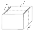
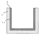
図1は、本発明に係るシリコン溶融ルツボの一例を示す斜視図であり、図2は、図1のA−A方向の断面図である。 FIG. 1 is a perspective view showing an example of a silicon melting crucible according to the present invention, and FIG. 2 is a cross-sectional view in the AA direction of FIG.
本実施形態に係るシリコン溶融ルツボは、図1及び図2に示すように、ルツボ本体1と、ルツボ本体1の内表面1a上に設けられた保護膜2とを備えている。
As shown in FIGS. 1 and 2, the silicon melting crucible according to the present embodiment includes a
ルツボ本体1は、耐熱性部材からなり、図1に示すように、例えば、全体が一体に成形された一体成形型のルツボで構成されている。なお、耐熱性部材としては、石英が好適に用いられる。この石英には、石英ガラスのみならず、溶融石英も含まれる。
The
保護膜2は、図2に示すように、ルツボ本体1の内表面1a上に設けられた単一層で構成されている。
As shown in FIG. 2, the
図3は、図2における保護膜2近傍の領域を拡大させた拡大概略断面図である。なお、図3に示す図はあくまで概略的なものであり、図3に示す固体粒子の形状や大きさ、固体粒子によって形成される保護膜2の厚さは、実際の寸法と異なる。
FIG. 3 is an enlarged schematic cross-sectional view in which a region in the vicinity of the
保護膜2は、図3に示すように、第1の固体粒子2aと、第1の固体粒子2aよりも粒径が小さい第2の固体粒子2bとを含有してなり、第2の固体粒子2bは、第1の固体粒子2a間の界面3の一部で前記第1の固体粒子2a同士を連結させた構成を備えている。
As shown in FIG. 3, the
前記第1の固体粒子2aは、少なくとも表面がSiOXNY(X>0、Y>0)組成を有している。 At least the surface of the first solid particles 2a has a composition of SiO X N Y (X> 0, Y> 0).
図4は、本発明に係る第1の固体粒子2aの具体的な構成を示す概略断面図である。 FIG. 4 is a schematic cross-sectional view showing a specific configuration of the first solid particles 2a according to the present invention.
第1の固体粒子2aは、具体的には、図4(a)に示すように、表面層2a1がSiOXNY(X>0、Y>0)で構成され、芯部2a2がシリカ(SiO2)で構成された固体粒子2aa、又は、図4(b)に示すように、表面層2a1がSiOXNY(X>0、Y>0)で構成され、芯部2a3が窒化珪素(Si3N4)で構成された固体粒子2ab、又は、図4(c)に示すように、粒子全体がSiOXNY(X>0、Y>0)で構成された固体粒子2acのいずれかで構成されている。 Specifically, in the first solid particle 2a, as shown in FIG. 4A, the surface layer 2a1 is composed of SiO X N Y (X> 0, Y> 0), and the core 2a2 is silica ( solid particles 2aa composed of SiO 2), or, as shown in FIG. 4 (b), the surface layer 2a1 is constituted by SiO X N Y (X> 0 , Y> 0), the core portion 2a3 is silicon nitride Solid particles 2ab composed of (Si 3 N 4 ) or solid particles 2ac composed entirely of SiO X N Y (X> 0, Y> 0) as shown in FIG. 4C. Consists of either.
第2の固体粒子2bは、SiO2組成を有する固体粒子、すなわち、シリカ粒子で構成されている。 The second solid particles 2b are composed of solid particles having a SiO 2 composition, that is, silica particles.
本発明に係るシリコン溶融ルツボは、上述したような構成を備えているため、シリコンブロックを該ルツボから脱型する際、保護膜とシリコンブロックとの付着に伴うシリコンブロックのカケや割れの発生を、保護膜自身が壊れることによって抑制することができる離型性に優れた保護膜を備える。 Since the silicon melting crucible according to the present invention has the above-described configuration, when the silicon block is removed from the crucible, the silicon block is not broken or cracked due to the adhesion between the protective film and the silicon block. And a protective film excellent in releasability that can be suppressed by breaking the protective film itself.
すなわち、本発明に係るシリコン溶融ルツボの保護膜を構成する第1の固体粒子2aは、上述したように、少なくとも表面がSiOXNY(X>0、Y>0)組成を有しているため、SiO2や、Si3N4よりも溶融シリコンと濡れ難いという効果を有する。また、第2の固体粒子2bは、前記第1の固体粒子2a間の界面3の一部で第1の固体粒子2a同士を連結させているため、保護膜2は、第1の固体粒子2a同士の剥がれが生じない程度に高い強度を有している。さらに、前述しているように、第2の固体粒子2bは、前記第1の固体粒子2a間の界面3の全体ではなく一部で、第1の固体粒子2a同士を連結させているため、全体で連結させるよりも強度的に低下している。従って、保護膜2の最表面に存在する第2の固体粒子2bや、仮に、第1の固体粒子2aとシリコンブロックとが付着しても、シリコンブロックを該ルツボから脱型する際、保護膜2が先に壊れてしまうため、保護膜2とシリコンブロックとの付着に伴うシリコンブロックのカケや割れの発生を防止することができる。
That is, as described above, at least the surface of the first solid particles 2a constituting the protective film of the silicon melting crucible according to the present invention has a composition of SiO X N Y (X> 0, Y> 0). Therefore, it has an effect that it is less likely to get wet with molten silicon than SiO 2 and Si 3 N 4 . In addition, since the second solid particles 2b connect the first solid particles 2a to each other at a part of the
前記第1の固体粒子2aの少なくとも表面に設けられたSiOXNY(X>0、Y>0)組成は、例えば、0.2≦X≦0.8、0.8≦Y≦1.2である。このX、Yの分析は、酸素・窒素同時分析法で求めることができる。 The composition of SiO X N Y (X> 0, Y> 0) provided on at least the surface of the first solid particle 2a is, for example, 0.2 ≦ X ≦ 0.8, 0.8 ≦ Y ≦ 1. 2. The analysis of X and Y can be obtained by the oxygen / nitrogen simultaneous analysis method.
前記第1の固体粒子2a、第2の固体粒子2bの粒径やその重量比は、前述したような保護膜2を形成することができれば特に限定されない。第1の固体粒子2aの粒径は、例えば、100nm以上1000nm以下であり、第2の固体粒子2bの粒径は、例えば、1nm以上10nm以下であり、第2の固体粒子2bの重量比は、例えば、第1の固体粒子2aに対して、0.1wt%以上5wt%以下である。
The particle size and weight ratio of the first solid particles 2a and the second solid particles 2b are not particularly limited as long as the
本発明に係る離型材としては、前述したような保護膜2を備えることができる材料で構成されている。すなわち、本発明に係る離型材は、少なくとも表面がSiOXNY(X>0、Y>0)組成を有する第1の固体粒子2aと、前記第1の固体粒子2aよりも粒径が小さいSiO2組成を有する第2の固体粒子2bと、を含有してなる粉体で構成されている。
The release material according to the present invention is made of a material that can include the
このような構成を備えた離型材を使用することで、上述した効果を有する保護膜を備えたシリコン溶融ルツボを得ることができる。 By using a release material having such a configuration, a silicon melting crucible having a protective film having the above-described effects can be obtained.
次に、ルツボ本体1に保護膜2を形成して、本実施形態に係わるシリコン溶融ルツボを製造する製造方法について説明する。
Next, a manufacturing method for manufacturing the silicon melting crucible according to the present embodiment by forming the
保護膜2に用いられる第1の固体粒子2aの製造には、原料として高純度(例えば、純度99.9%以上)のシリカ微粒子の集合体である粉体を用い、これを窒化処理することで、少なくとも表面がSiOXNY(X>0、Y>0)組成を有する固体粒子(図4(a)、(c))の粉体を製造し、これを離型材として使用する。又は、原料として高純度(例えば、純度99.9%以上)の窒化珪素微粒子の集合体である粉体を用い、これを酸化処理することで、少なくとも表面がSiOXNY(X>0、Y>0)組成を有する固体粒子(図4(b)、(c))の粉体を製造し、これを離型材(第1の固体粒子2a)として使用する。
For the production of the first solid particles 2a used for the
前記シリカ微粒子の窒化処理は、窒素系ガス含有雰囲気中(例えば、水素ガスとアンモニアガスとの混合ガス雰囲気中)、高温(例えば、1100℃)で所定時間熱処理を行うことにより、シリカ微粒子の少なくとも表面を窒化させることができる。なお、この窒化処理の処理条件(例えば、熱処理時間)を制御することにより、窒化率が異なるシリカ微粒子、すなわち、SiOXNY粉末を得ることができる。更に、熱処理時間をより長くすることで、粒子全体がSiOXNY(X>0、Y>0)で構成された固体粒子(図4(c))を製造することができる。 The nitriding treatment of the silica fine particles is performed by performing a heat treatment for a predetermined time at a high temperature (for example, 1100 ° C.) in a nitrogen-based gas-containing atmosphere (for example, in a mixed gas atmosphere of hydrogen gas and ammonia gas). The surface can be nitrided. By controlling the treatment conditions (for example, heat treatment time) of this nitriding treatment, silica fine particles having different nitriding rates, that is, SiO X N Y powder can be obtained. Furthermore, by making the heat treatment time longer, solid particles (FIG. 4C) in which the entire particles are composed of SiO X N Y (X> 0, Y> 0) can be produced.
前記窒化珪素微粒子の酸化処理は、酸化系ガス含有雰囲気中(例えば、大気雰囲気中)、高温(例えば、800℃)で所定時間熱処理を行うことにより、窒化珪素微粒子の少なくとも表面を酸化させることができる。なお、この酸化処理の処理条件(例えば、熱処理時間)を制御することにより、酸化率が異なる窒化珪素微粒子、すなわち、SiOXNY粉末を得ることができる。更に、熱処理時間をより長くすることで、粒子全体がSiOXNY(X>0、Y>0)で構成された固体粒子(図4(c))を製造することができる。なお、前記酸化処理により固体粒子表面に酸化膜SiO2(X=2、Y=0)が形成される場合には、希HF処理を行うことで前記酸化膜を除去することができる。 In the oxidation treatment of the silicon nitride fine particles, at least the surface of the silicon nitride fine particles is oxidized by performing a heat treatment for a predetermined time at a high temperature (for example, 800 ° C.) in an oxidizing gas-containing atmosphere (for example, in an air atmosphere). it can. In addition, by controlling the treatment conditions (for example, heat treatment time) of this oxidation treatment, silicon nitride fine particles having different oxidation rates, that is, SiO X N Y powder can be obtained. Furthermore, by making the heat treatment time longer, solid particles (FIG. 4C) in which the entire particles are composed of SiO X N Y (X> 0, Y> 0) can be produced. When the oxide film SiO 2 (X = 2, Y = 0) is formed on the solid particle surface by the oxidation treatment, the oxide film can be removed by performing dilute HF treatment.
また、保護膜2に用いられる第2の固体粒子2bには、第1の固体粒子2aよりも粒径が小さい高純度(例えば、純度99.9%以上)のシリカ微粒子の粉体を用いる。
Further, as the second solid particles 2b used for the
ルツボ本体1の内表面1aへの保護膜2の形成は、次のようにして行うことができる。
The formation of the
最初に、少なくとも表面がSiOXNY(X>0、Y>0)で構成された第1の固体粒子2a、第1の固体粒子2aよりも粒径が小さいSiO2組成を有する第2の固体粒子2b、純水およびバインダ(例えば、ポリビニルアルコール(PVA))を用いて懸濁液を作製する。この懸濁液を、例えば、凹形状のルツボ本体1の内表面1aへスプレー塗布し、乾燥させる。塗布膜が所望の厚さとなるまで、このスプレー塗布と乾燥とを繰り返す。
First, a first solid particle 2 a having at least a surface composed of SiO X N Y (X> 0, Y> 0), a second composition having a SiO 2 composition having a particle size smaller than that of the first solid particle 2 a A suspension is prepared using the solid particles 2b, pure water, and a binder (for example, polyvinyl alcohol (PVA)). For example, this suspension is spray-coated on the inner surface 1a of the
続いて、塗布膜が形成されたルツボ本体1を非酸化性雰囲気下(例えば、アルゴン雰囲気下)で所定温度(例えば、800℃)に加熱し、焼成する。
Subsequently, the
このとき、その昇温過程でバインダ(例えば、PVA)をガス化(焼失)させる。また、前記固体粒子が溶けて重力の作用で下方へ垂れて膜がずり落ちたり膜厚が変化したりすることのないように、塗布膜の内部に一定の空隙が残った状態で前記固体粒子同士を焼成して溶着させることが好ましい。こうしてルツボ本体1と密着した保護膜2を形成することができる。
At this time, the binder (for example, PVA) is gasified (burned out) in the temperature rising process. In addition, the solid particles remain in a state where a certain gap remains in the coating film so that the solid particles do not melt and sag downward due to the action of gravity and the film does not slide down or change in film thickness. It is preferable to fire and weld each other. Thus, the
本実施形態に係わるシリコン溶融ルツボは、上述したような製造方法で得ることができるため、研磨等の後処理や、CVD法を用いることなく、ルツボ本体への保護膜の形成が容易であるため生産経済性がよく、低コストで製造することができる。 Since the silicon melting crucible according to the present embodiment can be obtained by the manufacturing method as described above, it is easy to form a protective film on the crucible body without using post-processing such as polishing or CVD. Production economy is good and can be manufactured at low cost.
また、ここまで、前記ルツボ本体1を、一体成形型のルツボを例に挙げて説明したが、本願発明はこれに限定されることがなく、分割型のルツボを用いてもよい。なお、分割型のルツボを用いる場合の本実施形態に係わるシリコン溶融ルツボを製造する場合は、耐熱性部材からなる複数の板状体(図示せず)を準備し、その板状体の少なくとも一方の面に、上述したスプレー塗布、乾燥、焼成を行って、各々保護膜を形成した後、少なくとも保護膜が形成された面がルツボ形状とした際、内表面側になるように、前記複数の板状体を、接合部等を介して組み合わされることによって製造することができる。
Further, the
また、ルツボ本体は、石英で構成されていることが好ましい。 The crucible body is preferably made of quartz.
このような構成とすることで、前記第1の固体粒子2aや前記第2の固体粒子2bとルツボ本体1との熱膨張係数が他の材料に比べて近く又は同じとなり、組成差に起因する熱応力の発生が抑制されるため、シリコン溶融ルツボに熱的衝撃や物理的衝撃が生じた場合でも、保護膜2の破壊や剥離を防止することができる。
By adopting such a configuration, the thermal expansion coefficients of the first solid particles 2a and the second solid particles 2b and the
(実施例1)
高純度SiO2粉末(純度99.9%以上、平均粒径が100nmで、アルカリ金属,アルカリ土類金属,フッ化物,塩化物,炭素,鉄,クロム,コバルト,ニッケル,タングステン,モリブデン,チタンの合算濃度が2ppm)を、水素とアンモニアを体積比で1:3に調整した混合ガス雰囲気下、1100℃で5時間保持して、SiOXNY粉末を作製した。
Example 1
High purity SiO 2 powder (purity of 99.9% or more, average particle size of 100 nm, alkali metal, alkaline earth metal, fluoride, chloride, carbon, iron, chromium, cobalt, nickel, tungsten, molybdenum, titanium The total concentration was 2 ppm), and the mixture was held at 1100 ° C. for 5 hours in a mixed gas atmosphere in which hydrogen and ammonia were adjusted to a volume ratio of 1: 3 to prepare SiO X N Y powder.
こうして得られたSiOXNY粉末に対して、高純度SiO2粉末(純度99.9%以上、平均粒径が5nmで、アルカリ金属,アルカリ土類金属,フッ化物,塩化物,炭素,鉄,クロム,コバルト,ニッケル,タングステン,モリブデン,チタンの合算濃度が2ppm)を前記SiOXNY粉末に対して重量比で、0.1wt%混合し、純水とPVAとを用いて懸濁液を作製した。 With respect to the SiO X N Y powder thus obtained, high-purity SiO 2 powder (purity 99.9% or more, average particle size 5 nm, alkali metal, alkaline earth metal, fluoride, chloride, carbon, iron , Chromium, cobalt, nickel, tungsten, molybdenum, and titanium are mixed at a weight ratio of 0.1 wt% with respect to the SiO X N Y powder, and a suspension is prepared using pure water and PVA. Was made.
次に、内容積が678mm×678mm×400mmである溶融石英製のルツボ本体の内表面へ各々作製した懸濁液のスプレー塗布および乾燥を、膜厚が500μmとなるまで繰り返し行い、塗布膜を形成した。 Next, spray coating and drying of the prepared suspensions are repeatedly performed on the inner surface of the fused silica crucible body having an internal volume of 678 mm × 678 mm × 400 mm until the film thickness reaches 500 μm to form a coating film. did.
こうして塗布膜を形成したルツボを、塗布膜の内部に一定の空隙が残った状態で、非酸化性雰囲気(アルゴン雰囲気)中、800℃で60分保持して、保護膜を形成し、SiOXNY粒子とSiO2粒子とを備える保護膜が形成されたルツボを作製した。 The crucible thus formed with the coating film is held at 800 ° C. for 60 minutes in a non-oxidizing atmosphere (argon atmosphere) with a certain gap remaining inside the coating film to form a protective film, and SiO X A crucible in which a protective film comprising NY particles and SiO 2 particles was formed was produced.
(実施例2)
高純度Si3N4粉末(純度99.9%以上、平均粒径が100nmで、アルカリ金属,アルカリ土類金属,フッ化物,塩化物,炭素,鉄,クロム,コバルト,ニッケル,タングステン,モリブデン,チタンの合算濃度が2ppm)を、大気雰囲気下、800℃で5時間程度保持して、SiOXNY粉末を作製した。
(Example 2)
High purity Si 3 N 4 powder (purity 99.9% or more, average particle size 100 nm, alkali metal, alkaline earth metal, fluoride, chloride, carbon, iron, chromium, cobalt, nickel, tungsten, molybdenum, The total concentration of titanium was maintained at 800 ° C. for about 5 hours in an air atmosphere to prepare SiO X N Y powder.
その他は、実施例1と同様な方法で行い、SiOXNY粒子とSiO2粒子とを備える保護膜が形成されたルツボを作製した。 Others were carried out in the same manner as in Example 1 to produce a crucible on which a protective film comprising SiO X N Y particles and SiO 2 particles was formed.
(比較例1)
平均粒径が5nmの高純度SiO2粉末を用いないで、その他は、実施例1と同様な方法で、SiOXNY粒子のみを備える保護膜が形成されたルツボを作製した。
(Comparative Example 1)
A crucible on which a protective film having only SiO X N Y particles was formed was produced in the same manner as in Example 1 except that high-purity SiO 2 powder having an average particle diameter of 5 nm was not used.
(比較例2)
平均粒径が5nmの高純度SiO2粉末を用いないで、その他は、実施例2と同様な方法で、SiOXNY粒子のみを備える保護膜が形成されたルツボを作製した。
(Comparative Example 2)
A crucible on which a protective film having only SiO X N Y particles was formed was produced in the same manner as in Example 2 except that high-purity SiO 2 powder having an average particle diameter of 5 nm was not used.
(比較例3)
高純度Si3N4粉末(純度99.9%以上、平均粒径が100nmで、アルカリ金属,アルカリ土類金属,フッ化物,塩化物,炭素,鉄,クロム,コバルト,ニッケル,タングステン,モリブデン,チタンの合算濃度が2ppm)を、大気雰囲気下、1000℃で3時間加熱することで、Si3N4粒子の表面に酸化膜(SiO2)を形成させたSi3N4粉末を作製した。
(Comparative Example 3)
High purity Si 3 N 4 powder (purity 99.9% or more, average particle size 100 nm, alkali metal, alkaline earth metal, fluoride, chloride, carbon, iron, chromium, cobalt, nickel, tungsten, molybdenum, Si 3 N 4 powder in which an oxide film (SiO 2 ) was formed on the surface of Si 3 N 4 particles was manufactured by
こうして得られたSi3N4粉末に対して、前記平均粒径が5nmの高純度SiO2粉末を用いないで、純水とPVAとを用いて懸濁液を作製した。 With respect to the Si 3 N 4 powder thus obtained, a suspension was prepared using pure water and PVA without using the high-purity SiO 2 powder having an average particle diameter of 5 nm.
次に、内容積が678mm×678mm×400mmである溶融石英製のルツボ本体の内表面へ各々作製した懸濁液のスプレー塗布および乾燥を、膜厚が500μmとなるまで繰り返し行い、塗布膜を形成した。 Next, spray coating and drying of the prepared suspensions are repeatedly performed on the inner surface of the fused silica crucible body having an internal volume of 678 mm × 678 mm × 400 mm until the film thickness reaches 500 μm to form a coating film. did.
こうして塗布膜を形成したルツボを、塗布膜の内部に一定の空隙が残った状態でSi3N4粉末同士が溶着するように、非酸化性雰囲気(アルゴン雰囲気)中、800℃で60分保持して、保護膜を形成し、前記Si3N4粉末のみを備える保護膜が形成されたルツボを作製した。 The crucible on which the coating film has been formed in this way is held at 800 ° C. for 60 minutes in a non-oxidizing atmosphere (argon atmosphere) so that the Si 3 N 4 powders are welded with a certain gap remaining inside the coating film. Then, a protective film was formed, and a crucible in which a protective film having only the Si 3 N 4 powder was formed was produced.
(比較例4)
SiOXNY粉末を作製しないで、高純度SiO2粉末(純度99.9%以上、平均粒径が100nmで、アルカリ金属,アルカリ土類金属,フッ化物,塩化物,炭素,鉄,クロム,コバルト,ニッケル,タングステン,モリブデン,チタンの合算濃度が2ppm)のみを用い、その他は、実施例1と同様な方法で、前記SiO2粒子のみを備える保護膜が形成されたルツボを作製した。
(Comparative Example 4)
Without producing SiO X N Y powder, high purity SiO 2 powder (purity 99.9% or more, average particle size 100 nm, alkali metal, alkaline earth metal, fluoride, chloride, carbon, iron, chromium, A crucible on which a protective film having only the SiO 2 particles was formed was produced in the same manner as in Example 1 except that the total concentration of cobalt, nickel, tungsten, molybdenum, and titanium was used.
(保護膜のシリコンとの濡れ性の評価)
次に、上記作製したルツボに対して、多結晶シリコンの塊を積載し、加熱させてシリコン融液とし、その後、冷却固化させた。こうして作製したシリコンブロックから困難無くルツボ断片を除去できたもの「評価“A”」、シリコンブロックの最終固化部分に僅かなクラックが入った状態でルツボ断片を除去できたものを「評価“B”」、シリコンブロックとルツボが広範囲に接着し容易にルツボ断片を除去することができず、シリコンブロックに相当な破損が生じたものを「評価“C”」とした。
(Evaluation of wettability of protective film with silicon)
Next, a lump of polycrystalline silicon was loaded on the crucible produced above, heated to form a silicon melt, and then cooled and solidified. “Evaluation“ A ”” which was able to remove the crucible fragment from the silicon block thus produced without difficulty, and “Evaluation“ B ”” which was able to remove the crucible fragment with a slight crack in the final solidified portion of the silicon block. "Evaluation" C "" was a case where the silicon block and the crucible adhered in a wide range and the crucible fragments could not be easily removed, and the silicon block was considerably damaged.
(評価結果)
形成した保護膜のシリコンとの濡れ性の評価結果を表1に示す。
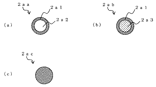
Table 1 shows the evaluation results of the wettability of the formed protective film with silicon.
なお、実施例1、2における保護膜の断面をSEMにて観察したところ、図3に示すような粒子構造を備えていることが確認された。 In addition, when the cross section of the protective film in Example 1, 2 was observed with SEM, it was confirmed that it has the particle structure as shown in FIG.
1 ルツボ本体
2 保護膜
3 界面
1
Claims (3)
前記保護膜は、少なくとも表面がSiOXNY(X>0、Y>0)組成を有する第1の固体粒子と、前記第1の固体粒子よりも粒径が小さいSiO2組成を有する第2の固体粒子とを含有してなり、
前記第2の固体粒子は、前記第1の固体粒子間の界面の一部で前記第1の固体粒子同士を連結させていることを特徴とするシリコン溶融ルツボ。 A silicon melting crucible provided with a protective film on at least the inner surface of a crucible body made of a heat-resistant member,
The protective film includes at least a first solid particle having a SiO X N Y (X> 0, Y> 0) composition on the surface, and a second SiO 2 composition having a particle size smaller than that of the first solid particle. Solid particles of
The silicon solid crucible characterized in that the second solid particles connect the first solid particles at a part of the interface between the first solid particles.
Priority Applications (4)
| Application Number | Priority Date | Filing Date | Title |
|---|---|---|---|
| JP2008250628A JP2010077003A (en) | 2008-09-29 | 2008-09-29 | Crucible for melting silicon and release agent used for the same |
| EP09005113A EP2116637A3 (en) | 2008-05-07 | 2009-04-07 | Crucible for melting silicon and release agent used to the same |
| US12/420,583 US20090277377A1 (en) | 2008-05-07 | 2009-04-08 | Crucible for melting silicon and release agent used to the same |
| CN2012100274445A CN102589286A (en) | 2008-05-07 | 2009-05-07 | Crucible for melting silicon and release agent used to the same |
Applications Claiming Priority (1)
| Application Number | Priority Date | Filing Date | Title |
|---|---|---|---|
| JP2008250628A JP2010077003A (en) | 2008-09-29 | 2008-09-29 | Crucible for melting silicon and release agent used for the same |
Publications (1)
| Publication Number | Publication Date |
|---|---|
| JP2010077003A true JP2010077003A (en) | 2010-04-08 |
Family
ID=42207882
Family Applications (1)
| Application Number | Title | Priority Date | Filing Date |
|---|---|---|---|
| JP2008250628A Withdrawn JP2010077003A (en) | 2008-05-07 | 2008-09-29 | Crucible for melting silicon and release agent used for the same |
Country Status (1)
| Country | Link |
|---|---|
| JP (1) | JP2010077003A (en) |
-
2008
- 2008-09-29 JP JP2008250628A patent/JP2010077003A/en not_active Withdrawn
Similar Documents
| Publication | Publication Date | Title |
|---|---|---|
| EP0134770B1 (en) | Carbonaceous articles having oxidation prohibitive coatings thereon | |
| CN102589286A (en) | Crucible for melting silicon and release agent used to the same | |
| JP2009269792A (en) | Silicon melting crucible and mold release agent used for it | |
| JP2020534237A (en) | Coatings for glass molding molds and molds containing them | |
| JP3723753B2 (en) | Method for producing a coating on a fire-resistant component and use of such a coating | |
| JP2017039997A (en) | Aluminum alloy-ceramic composite material and production method for aluminum alloy-ceramic composite material | |
| JPH11244988A (en) | Silicon ingot casting mold and method of manufacturing the same | |
| JP2010077003A (en) | Crucible for melting silicon and release agent used for the same | |
| JP2010077005A (en) | Crucible for melting silicon and release agent used for the same | |
| CN108585535B (en) | Production process of high-purity spraying-free crucible | |
| JP2010208866A (en) | Crucible for melting silicon | |
| JP3606744B2 (en) | Heat resistant material and method for producing the same | |
| JP4781232B2 (en) | Silicon melting crucible used in the manufacture of polycrystalline silicon blocks | |
| US10023972B2 (en) | Substrate for solidifying a silicon ingot | |
| CN103305826B (en) | The component of contact aluminum metal liquation and its manufacture method | |
| JP5788891B2 (en) | Silicon ingot manufacturing container | |
| JP2007273206A (en) | High-purity carbon electrode for arc melting and its application | |
| JP5846987B2 (en) | Release material for manufacturing silicon crystal ingot and method for forming release material for manufacturing silicon crystal ingot | |
| JP2002348174A (en) | Heat generation material mainly composed of MoSi2 having a low oxygen diffusible glassy film | |
| CN116162931B (en) | A kind of bottom blowing spray gun composite coating and its preparation method and bottom blowing spray gun | |
| JP2005161359A (en) | Method for coating mold for silicon casting, and mold for silicon casting | |
| JP2008239389A (en) | High temperature oxidation resistant carbonaceous molded body and method for producing the same | |
| JP2001181061A (en) | Inorganic fibrous molded article, heat insulating material, and method for producing them | |
| JP6334388B2 (en) | Graphite-silicon carbide composite and method for producing the same | |
| JP2013056782A (en) | Silicon casting mold and method for producing the same |
Legal Events
| Date | Code | Title | Description |
|---|---|---|---|
| A621 | Written request for application examination |
Free format text: JAPANESE INTERMEDIATE CODE: A621 Effective date: 20110901 |
|
| A521 | Written amendment |
Effective date: 20111021 Free format text: JAPANESE INTERMEDIATE CODE: A523 |
|
| A761 | Written withdrawal of application |
Free format text: JAPANESE INTERMEDIATE CODE: A761 Effective date: 20120709 |