JP2010077787A - Water antitheft hydrant upper part - Google Patents
Water antitheft hydrant upper part Download PDFInfo
- Publication number
- JP2010077787A JP2010077787A JP2008273581A JP2008273581A JP2010077787A JP 2010077787 A JP2010077787 A JP 2010077787A JP 2008273581 A JP2008273581 A JP 2008273581A JP 2008273581 A JP2008273581 A JP 2008273581A JP 2010077787 A JP2010077787 A JP 2010077787A
- Authority
- JP
- Japan
- Prior art keywords
- hydrant
- water
- faucet
- handle
- key
- Prior art date
- Legal status (The legal status is an assumption and is not a legal conclusion. Google has not performed a legal analysis and makes no representation as to the accuracy of the status listed.)
- Pending
Links
- XLYOFNOQVPJJNP-UHFFFAOYSA-N water Substances O XLYOFNOQVPJJNP-UHFFFAOYSA-N 0.000 title claims abstract description 58
- 230000002265 prevention Effects 0.000 claims description 2
- 230000001681 protective effect Effects 0.000 claims 1
- 239000008400 supply water Substances 0.000 abstract 1
- 239000013065 commercial product Substances 0.000 description 1
- 238000007599 discharging Methods 0.000 description 1
- 230000000694 effects Effects 0.000 description 1
- 238000012856 packing Methods 0.000 description 1
Images
Landscapes
- Domestic Plumbing Installations (AREA)
- Preventing Unauthorised Actuation Of Valves (AREA)
Abstract
Description
本発明は止水機能を有する給水栓の上部を共用給水栓すなわち給水栓の栓棒に給水ハンドルを固定することなく、給水時には水栓鍵を必要とする鍵式給水栓に関する。 The present invention relates to a key-type water faucet that requires a faucet key at the time of water supply without fixing a water supply handle to a common water faucet, that is, a stopper rod of the water faucet.
従来、鍵式共用給水栓においては、給水栓の上部である栓棒、給水ハンドルおよび取り付け袋ナットを給水ハンドルが着脱可能な鍵式共用給水栓が採用されている。この場合に、給水ハンドルと栓棒とのジョイントは、栓棒の先端には凸形の正四角柱、給水ハンドルの先端には凹型の正四角柱の形状を施し、この凹凸の結合により回転トルクを給水ハンドルから栓棒に伝え通水の開閉を可能とするものである。 Conventionally, in a key-type common water tap, a key-type common water tap in which a water supply handle can be attached to and detached from a plug bar, a water supply handle, and a mounting bag nut, which are the upper part of the water tap, has been adopted. In this case, the joint between the water supply handle and the plug rod is provided with a convex regular square column at the tip of the plug rod, and a concave regular square column at the tip of the water handle. It is possible to open and close water flow from the handle to the plug bar.
かかる構造から給水栓ハンドルである給水栓鍵がない場合は通水をすることができず、給水栓鍵を所有する者のみに水道の使用を可能とし、他人による水の使用を阻止することが可能となり盗水の防止を図ることができる。しかし、かかる従来の構造では以下の欠点が生じることになる。 If there is no faucet key that is a faucet handle, it is not possible to pass water, allowing only the person who owns the faucet key to use water, and preventing others from using the water. It becomes possible to prevent theft of water. However, this conventional structure has the following drawbacks.
第一に栓棒の先端部が凸形の正四角柱の形状であるため所定のレンチやペンチを使用すれば容易に給水栓の開閉が可能である。なによりも鍵式共用給水栓の上部は規格化されており何人も容易にその給水栓鍵を手に入れることが可能である。したがって、その盗水防止機能は十分なものであるとはいえない。 First, since the tip of the plug bar has a convex square prism shape, the water tap can be easily opened and closed by using a predetermined wrench or pliers. Above all, the upper part of the key-type shared hydrant is standardized so that anyone can easily obtain the hydrant key. Therefore, it cannot be said that the water theft prevention function is sufficient.
また、給水栓上部の袋ナットはレンチにより着脱可能であり、袋ナットを取り外せば先端部が凸型の正四角柱を有する栓棒がむき出しになり給水栓の開閉はより容易となるのである。 The cap nut at the top of the faucet can be attached and detached with a wrench. If the cap nut is removed, the plug bar having a square prism with a convex tip is exposed and the faucet can be opened and closed more easily.
これは、栓棒と給水栓ハンドルの先端部をそれぞれ凹凸のスプライン形状のローレットとしても同様に盗水を防止するのは困難である。 Similarly, it is difficult to prevent water theft even if the tip of the stopper rod and the faucet handle are each formed as an uneven spline-shaped knurl.
本発明は、所定の給水栓ハンドルを使用して初めて給水栓の操作を可能ならしめ、一般的な機械工具や規格化された共用給水栓鍵では給水栓の操作の困難性を図ることにある。 It is an object of the present invention to make it possible to operate a water faucet for the first time using a predetermined water faucet handle, and to make the operation of the water faucet difficult with a general machine tool or a standardized common water faucet key. .
そして現存する給水栓の上部のみを取り替えることにより本発明の課題を解決し、給水栓全体を取り替えるといった無用の工事を回避することにある。 And it is in solving the subject of this invention by replacing only the upper part of the existing water faucet, and avoiding the unnecessary work of replacing the whole water faucet.
本発明は栓棒と給水栓ハンドルの先端部にそれぞれ凹凸のスプライン形状のローレット部を有し、栓棒のローレット部は所定のハウジング内に位置し、レンチやプライヤーといった工具で栓棒を回転させることを阻止するものである。 The present invention has an uneven spline-shaped knurled portion at the tip of the stopper rod and the faucet handle, and the knurled portion of the stopper rod is located in a predetermined housing, and the stopper rod is rotated by a tool such as a wrench or a pliers. It is to prevent this.
そして、そのハウジングには栓棒と嵌合する給水栓ハンドルは挿入できるが、ラジオペンチ等でも容易に栓棒を操作し得ない鍵穴部を備える。 The housing is provided with a keyhole portion that can be inserted into the faucet handle that fits into the plug bar, but cannot be easily operated even with radio pliers or the like.
そして、給水栓上部の袋ナットには六角穴付き止めねじを装着することによりその取り外しを困難とするものである。 And the hexagon socket set screw is attached to the cap nut at the upper part of the water faucet to make it difficult to remove.
また、本発明の給水栓上部のハウジングには水抜きのリーク孔を有する。これは、栓棒が鉛直上向きに設置される場合に雨水等がハウジング内に溜まった場合、一定のはめあいを考慮しても、ハウジング内への給水ハンドルの挿入が困難となるからである。 Further, the housing above the faucet of the present invention has a drain hole for draining water. This is because, when rainwater or the like accumulates in the housing when the plug bar is installed vertically upward, it is difficult to insert the water supply handle into the housing even if a certain fit is taken into consideration.
本案発明の鍵付き共用給水栓を使用することで他人の給水栓の使用を阻止し、専用の給水栓ハンドルを所有する給水栓の所有者のみの使用を容易ならしめ、もって盗水の防止を可能とするものである。 By using the shared hydrant with the key of the present invention, the use of the hydrant of another person is prevented, and only the owner of the hydrant who owns the exclusive hydrant handle is made easy to prevent theft of water. It is possible.
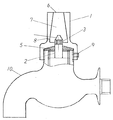
また、従来の鍵式共用給水栓の上部は栓棒がその先端を凸形の正四角柱という特殊な形状を必要とするため、横水栓等の給水栓を共用給水栓に変更する場合には、所定の栓棒に取り替える必要がある。この場合、栓棒を取り外す必要があり給水栓の止水機能が作用しないため、水道の元栓である止水栓を止めなければならないが、図1に示す請求項1の発明における共用給水栓上部は基の給水栓の栓棒をそのまま使用することも可能であるため、かかる煩を回避することができる。 In addition, the upper part of the conventional key-type common water faucet requires a special shape that the plug bar has a convex quadrangular prism at its tip, so when changing a water faucet such as a horizontal water faucet to a common water faucet It is necessary to replace it with a predetermined stopper rod. In this case, since it is necessary to remove the plug bar and the water stop function of the water tap does not work, it is necessary to stop the water tap which is the main tap of the water supply, but the upper part of the common water tap in the invention of claim 1 shown in FIG. Since it is possible to use the plug rod of the basic water faucet as it is, such trouble can be avoided.
以下、本発明の実施の形態を図1乃至図5に基づいて説明する。 Hereinafter, embodiments of the present invention will be described with reference to FIGS. 1 to 5.
図1において、1は栓棒2の袋ナットであって、栓棒2の回転操作を所定の給水栓ハンドルで可能とし、ラジオペンチで栓棒1をつまむことを困難とするハウジング部7を有する。開口部6の内径を小さくし、開口部6から栓棒2の先端部であるスプライン形状の凸形ローレット部3までの距離を長くすることで市販のラジオペンチではローレット部3をつかむことができず、栓棒2の回転操作は不可能となる。 In FIG. 1, reference numeral 1 denotes a cap nut of a
また、袋ナット1の開口部の内径形状をできるだけ小さくしておいて、そこからハウジング部への内径形状を半円錐形となるようなテーパー加工を施すことに。これによって、はめあい寸法をできるだけそのクリアランスが小さくなることができ、栓棒のローレット部3と給水栓ハンドル11のローレット部12とのジョイントにおけるフレキシブル性能を向上させることができるのである。 In addition, the inner diameter shape of the opening of the cap nut 1 is made as small as possible, and the inner diameter shape from there to the housing portion is tapered so as to be a semiconical shape. As a result, the clearance of the fitting dimension can be reduced as much as possible, and the flexible performance at the joint between the
さらに、ローレット部3の先端にテーパー部4を設けることにより栓棒のローレット部3をラジオペンチでつかもうとしても滑って、つかむことが困難となり、回転操作の阻止をより顕著なものとすることができる。 Further, by providing the tapered portion 4 at the tip of the
袋ナット1には雨水等を排出するためのリーク孔8を有し雨水等が袋ナット1のハウジングに溜まるのを防ぐことになる。 The cap nut 1 has a leak hole 8 for discharging rain water or the like, and rain water or the like is prevented from collecting in the housing of the cap nut 1.
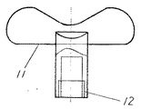
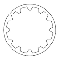
図2は給水栓ハンドル11の正面図を示し、図3は給水栓ハンドルのスプライン形状の凹ローレット部の下平面図を示す。ここで、12はスプライン形状の凹形ローレット部でありその外径は袋ナット1の開口部6に挿入可能なはめあい寸法である。 2 shows a front view of the
スプライン形状のローレットは規格化されており、規格外のローレット形状を採用する場合は一般市販品でのハンドル操作を不可能とし、専用の給水栓ハンドルが錠前の役目を果たし、更なる盗水防止の効果を図ることができる。 Spline-shaped knurls are standardized, and if a non-standard knurl shape is adopted, it is impossible to operate a handle on a general commercial product, and a dedicated hydrant handle serves as a lock, further preventing water theft The effect of can be aimed at.
図1において、袋ナット1にはそのねじ込み部に六角穴付き止めねじを備えることで容易に袋ナットを取り外すことができない。これは、袋ナット1を取り外すことで栓棒は露出することになり容易に栓棒を回転させ通水操作をすることができることを回避することができるのである。 In FIG. 1, a cap nut cannot be easily removed by providing the cap nut 1 with a hexagon socket set screw at its screwed portion. This is because the plug bar is exposed by removing the cap nut 1, and it is possible to avoid the fact that the plug bar can be easily rotated to perform a water flow operation.
1 袋ナット
2 栓棒
3 スプライン形状の凸ローレット部
4 栓棒の先端のテーパー部
5 パッキン
6 開口部
7 ハウジング
8 リーク孔
9 六角穴付き止めねじ
10 給水栓本体
11 給水栓ハンドル
12 スプライン形状の凹ローレット部DESCRIPTION OF SYMBOLS 1
Claims (1)
Priority Applications (1)
| Application Number | Priority Date | Filing Date | Title |
|---|---|---|---|
| JP2008273581A JP2010077787A (en) | 2008-09-25 | 2008-09-25 | Water antitheft hydrant upper part |
Applications Claiming Priority (1)
| Application Number | Priority Date | Filing Date | Title |
|---|---|---|---|
| JP2008273581A JP2010077787A (en) | 2008-09-25 | 2008-09-25 | Water antitheft hydrant upper part |
Publications (1)
| Publication Number | Publication Date |
|---|---|
| JP2010077787A true JP2010077787A (en) | 2010-04-08 |
Family
ID=42208504
Family Applications (1)
| Application Number | Title | Priority Date | Filing Date |
|---|---|---|---|
| JP2008273581A Pending JP2010077787A (en) | 2008-09-25 | 2008-09-25 | Water antitheft hydrant upper part |
Country Status (1)
| Country | Link |
|---|---|
| JP (1) | JP2010077787A (en) |
Cited By (3)
| Publication number | Priority date | Publication date | Assignee | Title |
|---|---|---|---|---|
| JP2013181303A (en) * | 2012-02-29 | 2013-09-12 | Lixil Corp | Handle device for faucet |
| WO2018150761A1 (en) * | 2017-02-15 | 2018-08-23 | ヤンマー株式会社 | Tractor |
| JP2020079085A (en) * | 2020-02-05 | 2020-05-28 | ヤンマー株式会社 | Tractor |
Citations (2)
| Publication number | Priority date | Publication date | Assignee | Title |
|---|---|---|---|---|
| JPS5845480U (en) * | 1981-09-24 | 1983-03-26 | 前沢給装工業株式会社 | valve |
| JP2001262641A (en) * | 2000-03-17 | 2001-09-26 | San-Ei Faucet Mfg Co Ltd | Lever faucet |
-
2008
- 2008-09-25 JP JP2008273581A patent/JP2010077787A/en active Pending
Patent Citations (2)
| Publication number | Priority date | Publication date | Assignee | Title |
|---|---|---|---|---|
| JPS5845480U (en) * | 1981-09-24 | 1983-03-26 | 前沢給装工業株式会社 | valve |
| JP2001262641A (en) * | 2000-03-17 | 2001-09-26 | San-Ei Faucet Mfg Co Ltd | Lever faucet |
Cited By (4)
| Publication number | Priority date | Publication date | Assignee | Title |
|---|---|---|---|---|
| JP2013181303A (en) * | 2012-02-29 | 2013-09-12 | Lixil Corp | Handle device for faucet |
| WO2018150761A1 (en) * | 2017-02-15 | 2018-08-23 | ヤンマー株式会社 | Tractor |
| JP2020079085A (en) * | 2020-02-05 | 2020-05-28 | ヤンマー株式会社 | Tractor |
| JP7011676B2 (en) | 2020-02-05 | 2022-01-26 | ヤンマーパワーテクノロジー株式会社 | Tractor |
Similar Documents
| Publication | Publication Date | Title |
|---|---|---|
| US7520294B2 (en) | Hydrant shoe with backflow prevention assembly | |
| KR100590910B1 (en) | Manhole with lock | |
| US7797972B2 (en) | Secure fire hydrant cap | |
| US2649825A (en) | Wrench and tap device | |
| JP2010077787A (en) | Water antitheft hydrant upper part | |
| JP2010053889A (en) | Water stop valve apparatus and water supply equipment using the same | |
| US7497228B2 (en) | Freeze and backflow protection for a subterranean water flushing system | |
| US5520210A (en) | Protective shield for fire hydrant | |
| US9951667B2 (en) | Rapid engine oil draining valve with protective covering | |
| KR20060129998A (en) | Pipe Angle Valve | |
| WO2007085250A1 (en) | A lock for fire hydrants | |
| US1343851A (en) | Lock for meters, &c. | |
| CN207862986U (en) | A kind of tree-protector of groundwater monitoring well | |
| US4062208A (en) | Locking means for gas valves | |
| KR100607601B1 (en) | Valve with lock | |
| KR200406175Y1 (en) | Manhole with lock | |
| JP6045911B2 (en) | Saddle faucet interior inspection method and inspection tool | |
| JP4395865B2 (en) | Lock bolt protection cap device for fixing manhole cover frame | |
| JP2004285694A (en) | Locking device for manhole cover | |
| US7040337B1 (en) | Valve override system | |
| GB2209156A (en) | Improvements in closures | |
| KR100618651B1 (en) | Valve Sealing Device | |
| JP5311746B2 (en) | Electrical equipment storage box | |
| KR20130023813A (en) | Ratchet handle for verticle type pipe valve | |
| JP5282066B2 (en) | Inspection lid locking device for hand holes |
Legal Events
| Date | Code | Title | Description |
|---|---|---|---|
| A621 | Written request for application examination |
Effective date: 20110819 Free format text: JAPANESE INTERMEDIATE CODE: A621 |
|
| A521 | Written amendment |
Free format text: JAPANESE INTERMEDIATE CODE: A523 Effective date: 20111005 |
|
| A977 | Report on retrieval |
Free format text: JAPANESE INTERMEDIATE CODE: A971007 Effective date: 20121214 |
|
| A131 | Notification of reasons for refusal |
Effective date: 20121225 Free format text: JAPANESE INTERMEDIATE CODE: A131 |
|
| A02 | Decision of refusal |
Effective date: 20130514 Free format text: JAPANESE INTERMEDIATE CODE: A02 |